Volume 2008, Article ID 970842,12pages doi:10.1155/2008/970842
Research Article
A Multigroup Priority Queueing MAC Protocol for
Wireless Networks with Multipacket Reception
Wen-Fang Yang, Jwo-Yuh Wu, Li-Chun Wang, and Ta-Sung Lee
Department of Communication Engineering, National Chiao Tung University, Hsinchu, Taiwan
Correspondence should be addressed to Wen-Fang Yang,[email protected]
Received 16 January 2008; Accepted 8 May 2008
Recommended by Yuh-Shyan Chen
Relying on a simple flag-assisted mechanism, a multigroup priority queueing (MGPQ) medium access control (MAC) protocol is proposed for the wireless networks with multipacket reception (MPR). The proposed MGPQ scheme is capable of overcoming two major performance bottlenecks inherent in the existing MPR MAC protocols. First, the proposed solution can automatically produce the list of active users by observing the network traffic conditions, remove the need of active user estimation algorithm, and thus can largely reduce the algorithm complexity. Second, the packet blocking constraint imposed on the active users for keeping compliant with prediction is relaxed. As a result, the proposed MGPQ is not only applicable to both homogeneous and heterogeneous cases, but also outperforms the existing MPR MAC protocols. Simulation results show that the network throughput can be improved by 40% maximum and 14% average as compared with the well-known dynamic queue (DQ) MAC protocol.
Copyright © 2008 Wen-Fang Yang et al. This is an open access article distributed under the Creative Commons Attribution License, which permits unrestricted use, distribution, and reproduction in any medium, provided the original work is properly cited.
1. INTRODUCTION
1.1. Overview
An efficient medium access control (MAC) mechanism is characterized by high throughput and low delay. Tradition-ally, the design of MAC protocols is based on the so-called collision channel model, that is, a transmitted packet is successfully received only when no concurrent transmission occurs. Such a paradigm, however, ignores the multipacket reception (MPR) capability at the physical layer, for example, multiuser detection [1]. Recently MAC protocols with the MPR capability draw increasing attention. Several proposals have been reported in the literatures [2–11], almost all of which are devised for the homogeneous environment, that is, all users are associated with the same packet generating probability. An initial attempt to reflect the MPR facility is the channel model with capture effect characterized via the probability of successful reception [2]. The impact of capture effects on various existing MAC protocols such as slotted ALOHA, and FCFS has been addressed in [3–5]. However, the capture model overall remains a simplified representation of the actual channel characteristics and does not explicitly account for the MPR capability. This thus
i Waiting slots Flag-bit Buffer Buffer
N
With packet Without packet Newly generated packet (a) The tag designating the status of theith user, 1≤i≤4
PREM
A
C
TIVE
ST
ANDBY
t−1
Start End
1 2
2 2 Off
On
3 4
1 1
Off On
t
Start End
1 1 Off
3 2 On N
4 2 On
2 1 Off
t+ 1 t+ 2
Start End
4 3 On
3 1 Off
2 2 Off
1 1 Off
(b) The priority grouping process within three consecutive time slots Figure1: An illustrative example of MGPQ with four users.
a predictive multicast polling (PMP) scheme was proposed for the general finite buffer size. This approach relies on active user prediction slot by slot, and can significantly improve system throughput since packet blocking is no longer necessary. However, the computational complexity is still a concern. The bit-map assisted dynamic queue (BMDQ) protocol [11], which is essentially a modified DQ scheme, inserts an extra TDMA slot at the head of each TP for channel access/reservation request. However, such an over-head will reduce the bandwidth efficiency, especially when the number of users is large. The two major performance bottlenecks inherent in the existing multipacket reception (MPR) MAC protocols are the computational complexity and the packet blocking constraints. In order to optimize the number of concurrent transmissions, the central controller may rely on an exhaustive search to estimate the buffer status of each user, thus resulting in a high-computational load. Second, the newly generated packets are not allowed to enter the buffer (hence blocked) for maintaining a static buffer status during each processing round.
1.2. Paper contributions
Relying on a simple flag-assisted mechanism and on an associated multipriority user grouping strategy, this paper proposes a new MPR MAC protocol which is applicable to both the homogeneous and heterogeneous cases. Com-pared with existing protocols, the proposed scheme through grouping users according to the prescribed service priority has two unique advantages. First, it avoids the search for the active users and thus reduces computational complexity [7,10]. Second, it is free from the packet blocking constraint and can further improve the throughput performance [7– 9]. Also, unlike [11] in which a longer overhead is appended for aiding protocol design, the proposed approach relies only
on a single bit redundancy and hence minimizes bandwidth expansion. The novel aspects of the proposed MPR MAC scheme can be specially summarized as follows.
(1) A single flag-bit is appended on the tail of the trans-mitted packet for indicating the existence of the following packet in the buffer. This scheme provides the central controller with the certain partial knowledge about the sub-sequent network traffic in adeterministicfashion. The flag-assisted information can greatly simplify the channel access which can be reserved directly for the users with packets ready to transmit. Note that thedeterministic knowledge is only available for those users whose packets are successfully received by the base station. Although the mechanism similar to the flag-bit may be available in the existing network protocol such as IEEE 802.11 [12], it is never exploited for facilitating the MPR MAC protocol design.
links with heavy traffic.) With the trigroup user classification scheme, the priorities of service (from high to low, resp.) are PREM, ACTIVE, and STANDBY. The proposed method integrates the deterministic knowledge of those users in the ACTIVE group and the estimated states of those users in the STANDBY group to derive the optimal waiting period for the PREM group.
(3) Through a Markov chain model of the proposed protocol and an associated analysis of the steady-state tran-sition probabilities, we propose a method for determining the optimal waiting period, subject to the constraint that a uniform mean delay requirement among all users must be met.
(4) In the proposed scheme, the number of users permitted for channel access is deterministically set to be that attaining the MPR channel capacity. This prevents the chan-nel from being overloaded and hence avoids irrecoverable packet collision in a heavy traffic environment.
The rest of paper is organized as follows. Section 2 introduces the MPR channel model.Section 3describes the proposed MGPQ protocol. The problem of optimal waiting period selection is addressed inSection 4. Simulation results are given inSection 5. Finally,Section 6concludes this paper.
2. MPR CHANNEL MODEL
Following [8], the MPR channel matrix for M users is described as
C=
⎡ ⎢ ⎢ ⎢ ⎢ ⎣
C1,0 C1,1 C2,0 C2,1 C2,2
..
. ... ...
CM,0 CM,1 CM,2 · · · CM,M
⎤ ⎥ ⎥ ⎥ ⎥
⎦, (1)
where
Cn,k=Pr{kpackets correctly received|npackets transmitted}
(2)
for 1 ≤ n ≤ M and 0 ≤ k ≤ n. Denote Cn =
n k=1kCn,k
the expected number of the correctly received packets when npackets are concurrently transmitted. The capacity of an MPR channel is defined asη=maxn=1,...,MCn. Note that the
numbers of simultaneously transmitted packets to achieve the channel capacity may not be unique. Let
n0=min arg max
n=1,...,M
Cn
(3)
be the minimum amount of capacity-achieving packets. Hence the maximal number of users permitted to access the channel should be n0, since there will be no further improvement in system capacity if more thann0 users are simultaneously served. Note that the MPR matrix (1) can be determined via the physical layer performance metric such
as bit error rate; an illustrative example based on CDMA communication can be found in [8].
3. MULTIGROUP PRIORITY QUEUEING PROTOCOL
3.1. System description
A centralized network typically involves two-side commu-nications, namely, downlink and uplink. The former is the transmission from the central controller to users, and the latter is the transmission from users to the central controller. As all the packets of downlink are stored at the buffer of the central controller, MAC can easily exploit the multipacket capability of PHY layer due to the full knowledge about the packet status for all users. Nevertheless, there must be some specially designed mechanism for scheduling the uplink transmission due to the lack of full knowledge about the status of users’ buffers in which the packets are stored. We will focus on the uplink in this paper. In the proposed system model, all accesses to the common wireless channel are controlled by the central controller. At the beginning of each slot, the central controller broadcasts an access set to inform the users who are allowed to access the channel in the current slot. Upon reception, the central controller acknowledges the users whose packets are successfully received. Users who transmit packets but do not receive the acknowledgments assume their packets are lost, and will retransmit whenever they are enabled. At the end of this slot, the central controller updates the access set by the proposed multipriority grouping strategy. In this paper, it is assumed that feedback acknowledgement channel (from the central controller to the users) is error free and the incurred time delay is negligible. As in [8], we assume that each user has a buffer of size two. We propose to append one flag bit on the tail of the transmitted packet for indicating if there is a following packet in the buffer. The extra flag bit has the advantage to provide explicit information about the incoming traffic condition, as discussed next.
3.2. An illustrative example
Figure 1 shows an illustrative example for the proposed MGPQ protocol, where the total number of users isM = 4 and n0 = 2 users are selected to simultaneously access the channel. In MGPQ, all users are classified into three different priority groups (PREM, ACTIVE, and STANDBY). The condition of the useriis summarized in a tag as shown in Figure 1(a), in which the first field represents user ID, second field is the count of waiting slots, third field marks the on/off status of the flag bit, fourth and fifth fields represent the contents of the buffer. Figure 1(b)depicts the operation of the proposed protocol during three consecutive time slots. At the end phase of slott−1, there is no user in the PREM group, user 1 with two packets and user 2 with one packet are in the ACTIVE group, and user 3 with one packet and user 4 with two packets are in the STANDBY group. The detailed operations of the proposed MGPQ are described as follows.
(2) At the end phase of slott,
(i) upon successful packet reception, user 1 with flag bit on in the start phase is retained in the ACTIVE group; the flag bit is then switched offsince there is no packet in the second buffer. User 2 is moved to the tail of the STANDBY group since the flag bit is off;
(ii) the waiting slots of both users 1 and 2 are reset to 1, and the waiting slots of the yet-to-be-served users 3 and 4 are increased to 2;
(iii) user 3 has a newly generated packet in the second buffer, and the associated flag bit is switched on.
(3) At the start phase of slott+ 1, there is no user in the PREM group and there is only one user in the ACTIVE group, so users 1 and 3 are selected.
(4) At the end phase of slott+ 1,
(i) upon successful packet reception, user 1 is moved to the tail of the STANDBY group (flag bit off). User 3 is moved into the ACTIVE group, and then flag-bit is switched off;
(ii) both the waiting slots of users 1 and 3 are reset to 1, and the waiting slots of the yet-to-be-served users 2 and 4 are increased to 2 and 3 respectively;
(iii) because user 4 has stayed in the STANDBY group for a certain waiting periodS=3 (to be specified later), it is moved into the PREM group.
(5) At the start phase of slott+ 2, there is one user in the PREM group and one user in the ACTIVE group, so users 4 and 3 will be selected.
3.3. Proposed MGPQ algorithm
The proposed MGPQ protocol is now stated as follows, and the resulting state transition conditions are summarized in Table 1.
(I) Put all users into the PREM group.
(II) Select firstn0users (by the order of PREM, ACTIVE, and then STANDBY group) to access the channel.
(a) If the packet of a certain user is received successfully, then put the user to the tail of the ACTIVE (if the flag-bit is on) or STANDBY group (if the flag-bit is off). And reset its count of waiting slots to zero. (b) If, for a certain user, the buffer is empty (no
packet sent) or there is packet transmitted but not successfully received, and then put the user back to the tail of the STANDBY or ACTIVE group in which the user originally stayed.
(III) Increase waiting slots of all users by one.
(IV) Move those users with waiting slots equal toSto the PREM group.
(V) Repeat steps (II) to (IV).
We note that, in the initial step, all users should be put in the PREM group rather than the STANDBY group. The rationale behind this choice is to avoid unfair scheduling
when the packet generating probability is high. Indeed, if the protocol starts with all users in the STANDBY group, the first-selected n0 users are likely to stay ACTIVE for a long time. The channel will thus be reserved for such ACTIVE users (with higher service priority), and those in the STANDBY group will then suffer a long delay.
3.4. Stability
System stability in the MAC design is extremely important since it guarantees all users with acceptable delays. A fixed packet arrival rate vector is stable if a transmission probability vector can be found to make all the queues in the corresponding system are stable [13]. However, it is difficult to derive the stability region for MPR protocols due to the complicated interactive queue behavior. Another approach to characterize the stability in the systems with finite buffer size is the absence of deadlock [14], or equivalently, all packets will be successfully received with finite delay. In this section, instead of finding the stability region, we will prove that the MGPQ MAC protocol is stable in terms of the finite-delay criterion.
According to the proposed protocol, the worst case occurs when a certain user is assigned with thelowestservice priority in the STANDBY group while having two packets in the buffer. In this case, the second buffered packet will experience the longest service delaydmax. To prove that the average ofdmaxis finite, we need the following two lemmas (the detailed proofs can be found in AppendicesAandB, resp.).
Lemma 1. Let pms be the minimal probability that a packet
can be successfully received. Then pms is bounded away from
zero. That is, there existsδ >0such thatpms≥δ >0.
Lemma 2. Lettkbe the total time slots elapsed afterkrounds
of channel access (k ≥ 1), and let tmax denote the maximal waiting slots for each access. Then we have
tk≤ktmax, (4)
where
tmax= ⎧ ⎪ ⎪ ⎪ ⎨ ⎪ ⎪ ⎪ ⎩
M n0
, if1≤S≤M n0,
S, if M n0< S <∞,
andSis the waiting period.
(5)
Based on the above two lemmas, the following theorem can be sustained.
Theorem 1. The mean worst-case delayE[dmax]satisfies
Edmax≤tmaxδ−1+M n0δ
−1<∞. (6)
Table1: Transition conditions among three different priority groups.
From To
PREM (1st priority) ACTIVE (2nd priority) STANDBY (3rd priority)
PREM (1st priority)
– without getting permission – transmitted packet (flag-bit=1) – transmitted packet (flag-bit=0)
to access the channel being successfully received being successfully received – transmitted packet not – transmitted packet not being
being successfully received, successfully received,
and previous flag-bit=1 and previous flag-bit=0
– no packet for transmission
ACTIVE (2nd priority)
– without getting permission – transmitted packet (flag-bit=1) – transmitted packet (flag-bit=0)
to access the channel being successfully received being successfully received
forSslots – transmitted packet not being
successfully received
– without getting permission to
access the channel for
less thanSslots
STANDBY (3rd priority)
– without getting permission – transmitted packet (flag-bit=1) – transmitted packet (flag-bit=0)
to access the channel being successfully received being successfully received
forSslots – transmitted packet not being
successfully received
– no packet for transmission
– without getting permission to
access the channel for less thanSslots
associated with the last-to-be-served user are successfully received, respectively. We first observe that
E[d1]
=
∞
k=1
tkPr{1st packet successfully received in thekth round}
≤tmax
∞
k=1
kPr{1st packet successfully received in the
kth round}
≤tmax ⎧ ⎪ ⎪ ⎨ ⎪ ⎪ ⎩pms
k=1 + 2pms
1−pms
k=2
+ 3pms
1−pms
2
k=3
+· · · ⎫ ⎪ ⎪ ⎬ ⎪ ⎪ ⎭
=tmax
∞
k=1 k pms
1−pms
k−1
=tmaxp−1
ms.
(7)
We note that the considered user will be moved to the ACTIVE group when the first packet is successfully received. In the worst-case,d2will incur when all theMusers are in the ACTIVE group. Therefore, the central controller will assign users to access the channel in a round-robin way, and the
average time slots elapsed per service round is thus M/n0. Thus, it is implied that
Ed2≤
M n0
pms
k=1 + 2
M n0
pms
1−pms
k=2 + 3
M n0
pms
1−pms
2
k=3
+· · ·
=M n0
∞
k=1 k pms
1−pms
k−1
=M n0p
−1
ms.
(8)
Combining (7) and (8), we obtain
Edmax=E[d1] +E[d2]≤tmaxp−1
ms+
M n0p
−1
ms
≤tmaxδ−1+M n0δ
−1<∞.
(9)
fixedn0 accesses, MGPQ is more robust in such a channel environment.
4. OPTIMAL WAITING PERIOD SELECTION
In the proposed protocol, the number of users permitted for channel access is fixed to ben0, namely, the one attaining the MPR channel capacity. A natural criterion for determining the waiting periodSis to maximize the probability thateach of the selectedn0users has a packet to send. We first note the probability of the useri(selected from PREM) with a packet to transmit after waiting a period ofSis at least [15]
pi:=1−
1−pi
S
, i∈ {1, 2,. . .,M}, (10)
where pi denotes the packet generating probability of the
user i. This implies that the larger the waiting period S, the more likely the users in the PREM group have packets to send. As a result, Sshould be kept as large as possible. However, the unlimited increase inSmay incur severe delay penalty. Particularly ifS→∞, the transition from STANDBY to PREM is prevented and the proposed trigroup priority queuing protocol degenerates into a bigroup scheme. To determine anSfor striking a balance between large pi and
small delay, we propose to seek the optimalSoptwith which the following set of constraints on the mean delay per user is satisfied:
Di(S)≤Dr, 1≤i≤M, (11)
whereDi(S) stands for the mean delay of the useriandDris
a uniform delay requirement.
To find the desired S from (11), one crucial step is to determine an explicit expression of Di(S) in terms of
S. Toward this end, we shall determine all the possible transitions of states (an exact definition of a “state” will be specified later) in the proposed protocol. This can be solved by applying Markov chain analysis shown below.
4.1. Markov chain
Associated with the user i (1 ≤ i ≤ M), we definexi(t),
yi(t), andzi(t) to be the assumed value of the waiting slots,
the indication of the flag, and the number of packets in the buffer at the tth time slot, respectively. Hence we have xi(t) ∈ {1,. . .,S}, yi(t) ∈ {0, 1}, and zi(t) ∈ {0, 1, 2}.
(The waiting period S ≥ M/n0 and the buffer of size two are assumed hereafter if not specified otherwise.) Let us further collectxi(t), yi(t), andzi(t) for all users to form
X(t) = (x1(t),. . .,xM(t)), Y(t) = (y1(t),. . .,yM(t)), and
Z(t) = (z1(t),. . .,zM(t)). The proposed protocol can be
modeled by a Markov chain with state space
Ω:= E(t)|E(t)=X(t),Y(t),Z(t), t≥1!. (12)
We note that the number of states is at most (S·2·3)M
. However, since in each time slot, exact n0 users can simultaneously access the channel, it follows that (i) the number of “1” in X(t) must be equal ton0; (ii) no more thann0entries inX(t) will assume the same value. Taking the
above constraints into account and using the permutation and combination theory, the number of distinct outcomes of X(t) is (seeAppendix Cfor proof)
NC= M!
n0!M−n0!·
mi
(S−1)! "n0
i=0
mi!
·
M−n0! "n0
i=0(i!)
mi, (13)
where the integers mis are found as the solutions to the
following equations:
n0
i=0
i·mi=M−n0,
n0
i=0
mi=S−1.
(14)
With (13) and the constraint that there must be packet(s) in the buffer for the users in the ACTIVE group (i.e., (yi,zi)=(1, 0)), the total number of possible states in the/
system can be reduced to
NS=NC·5M. (15)
If there exists some pi = 0 or 1, the total number of states
will be further reduced.
4.2. State transition probability
We proceed to compute the state transition probabilities as follows. Assuming that the events of packet generation among users are independent, we have
Pr E(t+ 1)= X,Y,Z
|E(t)=(X,Y,Z)!
=
M
#
i=1 Px
Δxi
Py
Δyi
Pz
Δzi
,
(16)
whereX−X=(Δx1,. . .,ΔxM),Y−Y=(Δy1,. . .,ΔyM), and
Z−Z = (Δz1,. . .,ΔzM);Px(Δxi),Py(Δyi), andPz(Δzi) are
the probabilities of the increment of state components given (X,Y,Z) (see Appendix Dfor details). Based on the state transition probabilities (16), we can immediately construct the transition matrix TNS×NS, with which the steady-state
probabilityπj, 1≤j≤NS, can be readily obtained by
lim
t→∞T
t=
⎡ ⎢ ⎢ ⎢ ⎢ ⎣
π1 π2 · · · πNS π1 π2 · · · πNS
..
. ... . .. ... π1 π2 · · · πNS
⎤ ⎥ ⎥ ⎥ ⎥
⎦. (17)
In this paper, we assume that the above limit exists, and the assumption is justified by numerical results. The mean delay Di(S) can be then determined as follows.
4.3. Computation of the mean delay
According to Little’s law [16], we have
whereNi(S) is the average number of packets in the buffer
of the user i, and λi(S) is the packet departure rate (i.e.,
throughput) of the useri. Letzi,jbe the number of buffered
packets of the useriin the jth state, then we have
Ni(S)= NS
j=1
πjzi,j. (19)
Also, denoted by pB,i(S) the packet blocking probability of
useri, therefore
pB,i(S)=
1≤j≤NS,zi,j=2,i /∈A πj +
1≤j≤NS,zi,j=2,i∈A πj
1−PS
,
(20)
where access setAand success probabilityPSare defined in
Appendix D. Then it follows that
λi(S)=pi
1−pB,i(s)
. (21)
Substituting (19) and (21) into (18), we can obtain a functional relation of Di(S) in terms of S. The solution to
(11) can then be computed via numerical search.
4.4. Homogeneous case
In the homogeneous environment, that is, the packet gener-ating probabilities of all users are identical, it can be shown that the mean delay in (18) is independent of waiting period S(the detailed proof is referred toAppendix E). An intuitive explanation of this phenomenon is that, when subject to the same packet generating probability, all users tend to share the same service priority, and hence experience the same average service delay irrespective of the choice ofS.
4.5. Extension to finite buffer size
Although the previous derivation is obtained under the assumption that each user has a buffer of size two, it can be easily extended to the case with finite buffer size B by allowingzi(t) ∈ {0, 1, 2,. . .,B}. TheNS in (15) must also
be increased toNC(2B+ 1)M accordingly. This case will be
simulated and compared with other MPR MACs in the next section.
5. NUMERICAL RESULTS
In this section, simulations are carried out by Matlab and we first compare the results with the theoretical analysis for a simple scenario to validate the derivation inSection 4. In this paper, throughput is defined as the average of successful packet transmissions per slot; delay is defined as the average elapsed time slots for a packet to be successfully received by central controller; packet loss ratio (PLR) is defined as the average ratio of the number of blocked packets to the number of generated packets. Then in the heterogeneous case, the individual delay curves with increasing S are plotted to show the effect of S on system performance. In the homogeneous case, throughput, delay, and PLR of
MGPQ are further compared with those of DQ. Finally, the throughput performance with more users and finite buffer size of MGPQ, predictive multicast polling (PMP) [10], and DQ [8] are compared to verify their scalability.
5.1. Validation of analytical results
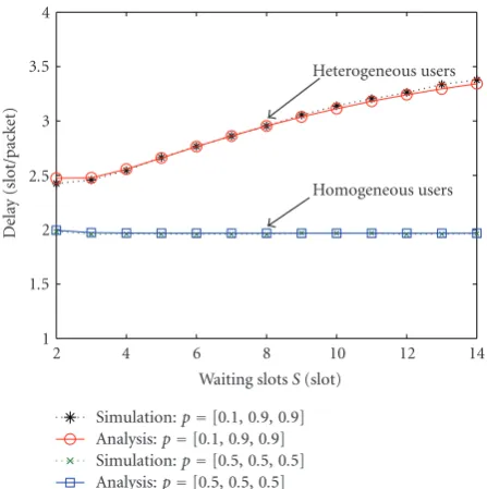
This simulation aims at validating the analytical performance results in Section 4. The test system is a CDMA network with random spreading; the packet length, spreading gain, number of correctable errors in a packet, and noise variance are, respectively, 200, 6, 2, and 10 dB as adopted in [8]. The capacity of such an MPR channel in this scenario is 1.7925, which is attained byn0=2 concurrent transmissions in each time slot. The total number of users is set to be M = 3. We note that the incurred overhead due to the insertion of a flag bit is 1/201 < 0.005, which is rather small and is thus neglected in the performance evaluation. Figures 2 and 3, respectively, show the mean throughput and mean delay curves for the two scenarios: (i) the heterogeneous case with packet generating probabilities [p1,p2,p3] = [0.1, 0.9, 0.9], and (ii) the homogeneous case with an equal packet generating probability p1 = p2 = p3 = 0.5. As we can see from the figures, in both cases the theoretical results well predict the corresponding simulated outcomes. It can also be seen that, in the homogeneous environment, the mean throughput and mean delays remain unchanged as the waiting period increases: this confirms the assertion in Section 4.4. For the heterogeneous case, we impose the mean delay requirement of each user to be less than 4 time slots; by using the results inSection 4.3, the optimal waiting period is computed to beSopt=7.Figure 4depicts the mean delay of each user. It can be seen that the delays of all the three users are indeed kept below 4 when S = Sopt = 7. We also note fromFigure 4that users with large (or small, resp.) packet generating probabilities pi experience less (or more) delay.
This is not unexpected since, ifpiis large, the flag bit will be
on with a high probability and the user will be allowed for accessing the channel more frequently.
5.2. Comparison with previous work of [8]
1 1.1 1.2 1.3 1.4 1.5 1.6 1.7 1.8 1.9 2
Thr
o
ug
hput
(pac
ke
t/slot)
2 4 6 8 10 12 14
Waiting slotsS(slot)
Heterogeneous users
Homogeneous users
Simulation:p=[0.1, 0.9, 0.9] Analysis:p=[0.1, 0.9, 0.9] Simulation:p=[0.5, 0.5, 0.5] Analysis:p=[0.5, 0.5, 0.5]
Figure2: Mean throughput performance of the proposed MGPQ.
1 1.5 2 2.5 3 3.5 4
Dela
y
(slot/pack
et)
2 4 6 8 10 12 14
Waiting slotsS(slot)
Heterogeneous users
Homogeneous users
Simulation:p=[0.1, 0.9, 0.9] Analysis:p=[0.1, 0.9, 0.9] Simulation:p=[0.5, 0.5, 0.5] Analysis:p=[0.5, 0.5, 0.5]
Figure3: Mean delay performance of the proposed MGPQ.
have packets to send, thus avoiding the time latency incurred by the procedure of network-wide active user prediction. In a heavy-traffic environment, the DQ protocol will block the incoming packets, thereby reduce the mean delay. However, this comes at the expense of a larger PLR, as evidenced in Figure 7.
5.3. General case
In this simulation, we test the proposed protocol with finite buffer size, and compare the performance with the DQ [8]
1 2 3 4 5 6 7
Dela
y
(slot/pack
et)
2 4 6 8 10 12 14
Waiting slotsS(slot)
Dr=4
Sopt=7
Simulation, user 1:p=0.1 Simulation, user 2:p=0.9 Simulation, user 3:p=0.9 Analysis, user 1:p=0.1 Analysis, user 2 & 3:p=0.9
Figure4: Delay performance of individual users.
0 0.2 0.4 0.6 0.8 1 1.2 1.4 1.6 1.8 2
Thr
o
ug
hput
(pac
ke
t/slot)
0 0.1 0.2 0.3 0.4 0.5 0.6 0.7 0.8 0.9 1 Packet generating probabilityp
MGPQ,S=10 MGPQ,S=20
DQ
Slotted ALHOA
Figure5: Throughput performance comparison between MGPQ and DQ.
and PMP [10] methods (the latter is specifically devised for the case with finite buffer size). We consider the system setup as in [10] which is described in terms of the MPR matrix as
C=
⎡ ⎢ ⎢ ⎢ ⎢ ⎢ ⎢ ⎣
0 1 0 0 1 1 0 0 0
.. . ... ... 1 0 0 · · · 0
⎤ ⎥ ⎥ ⎥ ⎥ ⎥ ⎥ ⎦
0 1 2 3 4 5 6 7 8 9 10 11
Dela
y
(slot/pack
et)
0 0.1 0.2 0.3 0.4 0.5 0.6 0.7 0.8 0.9 1 Packet generating probabilityp
MGPQ DQ, average
Figure6: Delay performance comparison between MGPQ and DQ.
0 0.1 0.2 0.3 0.4 0.5 0.6 0.7 0.8 0.9
Pa
ck
et
lo
ss
ra
te
0 0.2 0.4 0.6 0.8 1 1.2 1.4 1.6 1.8 2 Throughput (packet/slot)
MGPQ DQ
Figure 7: Packet loss ratio performance comparison between MGPQ and DQ.
thus with n0 = 2,η = 2, and set the total traffic load to be the same with channel capacity. Figure 8 shows the throughput curves of the three methods as the buffer size increases from 2 to 100. It is seen that the DQ scheme results in the lowest throughput, mainly due to the packet blocking constraint. The proposed MGPQ protocol outperforms the PMP solution, thanks to the benefits from the priority mechanism which can reduce the blocking rate especially when the buffer size is small. Figure 9 further depicts the respective throughput performance as the number of user increases from 2 to 100. The result shows that the DQ protocol degrades the performance severely when there are
1 1.2 1.4 1.6 1.8 2 2.2
Thr
o
ug
hput
(pac
ke
t/slot)
100 101 102
Buffer size MGPQ
PMP DQ
Figure8: Throughput comparison between MGPQ, PMP, and DQ for different buffer sizes.
1 1.2 1.4 1.6 1.8 2 2.2
Thr
o
ug
hput
(pac
ke
t/slot)
100 101 102
Number of usersM
MGPQ PMP DQ
Figure9: Throughput comparison between MGPQ, PMP, and DQ for different number of users.
more than two users. This is mainly because in the DQ protocol all users, no matter with packet or not, will be served continually until their packets are received successfully or empty slot occurs. With more thann0 users in the system, the probability of serving idle users is definitely increased.
6. CONCLUSION
buffered packets as well as a multipriority user grouping strategy. The advantages of the proposed method are three folds: (1) it is applicable to both the heterogeneous and homogeneous environments, whereas almost all existing protocols developed for the MPR channel are exclusively tailored for the latter case; (2) the insertion of a single bit facilitates the acquisition of network traffic condition with minimal bandwidth expansion; (3) the adopted user grouping policy avoids computationally intensive search for the active users as required in the existing protocols. To prevent an infinitely long service delay in the heterogeneous environment, the waiting period of those yet-to-be-served users can be determined subject to a specified delay require-ment. Simulation results show that, compared with the DQ protocol, the proposed scheme achieves higher throughput, reduces the mean delay penalty in light traffic condition, and yields a smaller packet loss ratio. Also, the proposed MGPQ protocol outperforms the predictive multicast polling (PMP) protocol for the general case with finite buffer size. Future work will focus on generalizing the result in this paper to the more realistic generalized MPR channel model [17].
APPENDICES
A. PROOF OFLEMMA 1
According to the definition ofηinSection 2, we have
η=
n0
k=1
k·Cn0,k= n0−1
k=1
k·Cn0,k+n0·Cn0,n0. (A.1)
IfCn0,n0=0, then (A.1) becomes
η=
n0−1
k=1
k·Cn0,k≤ n0−1
k=1
k·Cn0−1,k=η, (A.2)
whereη corresponds to a higher or equal channel capacity but achieved by sending n0 − 1 packets simultaneously. Note that the inequality in (A.2) holds because the success probability of transmitting more packets simultaneously is less than or equal to that of transmitting less packets under the same channel condition, that is,Cn0,k≤Cn0−1,k. Because
(A.2) conflicts with the definition of channel capacity, we conclude thatCn0,n0 >0 with proof by contradiction. Thus,
we havepms≥Cn0,n0=δ >0.
B. PROOF OFLEMMA 2
We first derive thetmaxas follows. For 1≤S≤M/n0, do the following.
Let nPREM, nACTIVE, and nSTANDBY denote the number of users in the PREM, ACTIVE, and STANDBY groups, respectively, and then we have
nPREM+nACTIVE+nSTANDBY=M. (B.1)
Because the user with waiting slots equal toSwill be moved to the PREM group, the waiting slots of the users in the ACTIVE and STANDBY groups must be less thanS, that is,
equal to 1, 2,. . ., orS−1. Besides, asn0users are selected to access the channel in each slot, the maximal number of users with the same waiting slots must be less than or equal ton0. Therefore, it can be seen that
nACTIVE+nSTANDBY≤(S−1)n0≤
M n0 −1
n0=M−n0.
(B.2)
Combining (B.1) and (B.2), we have
nPREM=M−nACTIVE+nSTANDBY≥M−M−n0=n0. (B.3)
Equation (B.3) shows that there will always be at least n0 users in the PREM group waiting for channel access, which implies that all users will be selected (n0users per slot) to access the channel in turn in the PREM group, that is,
tmax=
M n0
. (B.4)
ForM/n0< S <∞, the following hold.
According to the MGPQ protocol defined inSection 3.3, all users are in the PREM group initially. AfterM/n0slots, there will be less than n0 users left in the PREM group becauseM− M/n0n0< n0; and no user reenters the PREM group becauseM/n0 ≤M/n0< S. Hereafter, the input rate of the PREM group is less than or equal to the output rate (n0/slot) of the PREM group, which implies that the users entering the PREM group will be immediately selected to access the channel, that is,tmax=S.
C. PROOF OFNCIN(13)
It is known from the multinomial theorem that [15] $
n k1,k2,. . .,km
%
= n!
k1!k2!· · ·km!
, where
m
i=1 ki=n.
(C.1)
The above multinomial coefficient can be interpreted as the number of distinct ways to permute a multiset ofnelements, and ki’s are the multiplicities of each distinct element.
According to the MGPQ protocol defined in Section 3.3, there will be always exactlyn0users whose waiting slots are one. However, there may be 0 to n0 users with the same waiting slots ranging from 2 toS, because the users in the ACTIVE group may be selected with higher priority than those in the STANDBY group. Letmistand for the number
of distinct waiting slots whichiusers have waited for, 0≤i≤ n0. Then we have
NC= M!
n0!M−n0!
(a)
·
mi
(S−1)! "n0
i=0
mi!
(b) ·
M−n0! "n0
i=0
i!mi
(c) ,
where
n0
i=0
mi=S−1
,
(d)
n0
i=0
i·mi=M−n0
(e) .
In (C.2), (a) is the possible combinations for distinct n0 users whose waiting slots equal 1; (b) accounts for possible combinations of mi’s in the remaining S−1 waiting slots;
(c) accounts for possible combinations ofi’s in the remaining M−n0users; (d) is the constraint for multinomial coefficient (b), that is, summation ofmi’s must equalS−1; and (e)
is the constraint for multinomial coefficients (c), that is, summation of users in eachmi’s must equalM−n0.
D. DESCRIPTION OF STATE TRANSITION PROBABILITY INSECTION 4.2
Denoted byA = {a1,a2,. . .,an0}the index set of the users
who are allowed to access the channel. Also, letna be the
number of nonzero elements in{za1,za2,. . .,zan0}, that is, the
number of packets that will be sent simultaneously. DefinePS
as the success probability of selected user with packet to send in each slot, then
PS=
Thus, the probabilities of the increment of state forX,Y, Zcomponents, that is,Px(Δxi),Py(Δyi), andPz(Δzi) can be
calculated by (D.2) according to current state (X,Y,Z). Px
E. PROOF OF STATEMENT INSECTION 4.4
If each user has equal packet generating probability, without loss of generality, we can write the transition matrix as
T = G⊗H by appropriate ordering of states, where G
is the NC ×NC transition matrix of state X(t), H is the
5M×5Mtransition matrix of state (Y(t),Z(t)), and⊗stands
for Kronecker product. NoteG(including size and contents) is the function of the waiting period selectionS, andHis the function of packet generating probability.
To compute the steady-state probabilities, let
G=
According to the property of Kronecker product, we have
Substituting (E.3) into (20), we have
pB,i(S)=
1≤j≤NS,zi,j=2,i /∈A πj +
1≤j≤NS,zi,j=2,i∈A
πj(1−PS)
=
NC
α=1 5M
β=1,i /∈A
gαhβδ
zi,β−2
+
NC
α=1 5M
β=1,i∈A
gαhβδ
zi,β−2
1−PS
=
NC
α=1 gα
$ 5M
β=1,i /∈A
hβδ
zi,β−2
+ 5M
β=1,i∈A
hβδ
zi,β−2
1−PS
%
= 5M
β=1,i /∈A
hβδ
zi,β−2
+
5M
β=1,i∈A
hβδ
zi,β−2
1−PS
PB.
(E.5)
Substituting (E.5) into (21), we have
λi(S)=pi
1−pB,i(S)
=p1−PB
Λ. (E.6)
Note that the zi,j in (E.4) and (E.5) is replaced with zi,β,
because it is not related withgα. Substituting (E.4) and (E.6)
into (18), we have
Di(S)=Ni(S)/λi(S)=NB/ΛD. (E.7)
The above derivations prove the throughput (E.6), mean delay (E.7), and blocking probability (E.5) of the system with equal packet generating probability are the functions of packet generating probabilities, but independent ofS.
ACKNOWLEDGMENTS
This work is sponsored by the National Science Council of Taiwan under grant NSC 95-2752-E-002-009 and 96-2628-E-009-003-MY3, by the Ministry of Education of Taiwan under the MoE ATU Program, and by MediaTek research center at National Chiao Tung University, Taiwan.
REFERENCES
[1] L. Tong, Q. Zhao, and G. Mergen, “Multipacket reception in random access wireless networks: from signal processing to optimal medium access control,” IEEE Communications Magazine, vol. 39, no. 11, pp. 108–112, 2001.
[2] M. Sidi and I. Cidon, “Splitting protocols in presence of capture,”IEEE Transactions on Information Theory, vol. 31, no. 2, pp. 295–301, 1985.
[3] I. M. I. Habbab, M. Kavehrad, and C.-E. W. Sundberg, “ALOHA with capture over slow and fast fading radio channels with coding and diversity,”IEEE Journal on Selected Areas in Communications, vol. 7, no. 1, pp. 79–88, 1989.
[4] M. Zorzi, “Mobile radio slotted ALOHA with capture and diversity,”Wireless Networks, vol. 1, no. 2, pp. 227–239, 1995.
[5] M. Zorzi and R. R. Rao, “Capture and retransmission control in mobile radio,”IEEE Journal on Selected Areas in Communications, vol. 12, no. 8, pp. 1289–1298, 1994. [6] S. Ghez, S. Verdu, and S. C. Schwartz, “Optimal decentralized
control in the random access multipacket channel,” IEEE Transactions on Automatic Control, vol. 34, no. 11, pp. 1153– 1163, 1989.
[7] Q. Zhao and L. Tong, “A multiqueue service room MAC protocol for wireless networks with multipacket reception,” IEEE/ACM Transactions on Networking, vol. 11, no. 1, pp. 125– 137, 2003.
[8] Q. Zhao and L. Tong, “A dynamic queue protocol for multiaccess wireless networks with multipacket reception,” IEEE Transactions on Wireless Communications, vol. 3, no. 6, pp. 2221–2231, 2004.
[9] M. Realp and A. I. P´erez-Neira, “PHY-MAC dialogue with multi-packet reception,” in ETSI Workshop on Broadband Wireless Ad-Hoc Networks and Services, Sophia Antipolis, France, September 2002.
[10] R.-H. Gau and K.-M. Chen, “Predictive multicast polling for wireless networks with multipacket reception and queuing,” IEEE Transactions on Mobile Computing, vol. 5, no. 6, pp. 725– 737, 2006.
[11] X. Wang and J. K. Tugnait, “A bit-map-assisted dynamic queue protocol for multiaccess wireless networks with multiple packet reception,”IEEE Transactions on Signal Processing, vol. 51, no. 8, pp. 2068–2081, 2003.
[12] ANSI/IEEE Standard 802.11b–1999 (R2003), “Wireless lan medium access control (MAC) and physical layer (PHY) specifications: higher-speed physical layer extension in the 2.4ghz band,” IEEE SA Standards Board, Tech. Rep., 1999. [13] M. X. Cheng, Y. Li, and D.-Z. Du, Eds., Combinatorial
Optimization in Communication Networks, Springer, New York, NY, USA, 2006.
[14] H. M. Deitel,An Introduction to Operating Systems, chapter 6, Addison-Wesley, Reading, Mass, USA, 1984.
[15] A. Papoulis, Probability, Random Variables, and Stochastic Processes, McGraw-Hill, New York, NY, USA, 2nd edition, 1984.
[16] L. Kleinrock,Queueing Systems. Volume 1: Theory, John Wiley & Sons, New York, NY, USA, 1975.