Material Removal Phases in Single Abrasive
Grain Grinding
Tahsin Tecelli Öpöz and Xun Chen
Centre for Precision Technologies, School of Computing and Engineering University of Huddersfield, HD1 3DH, Huddersfield, UK.
Abstract. In this research, basic material removal characteristics in a single grit grinding have been investigated by using Finite Element Analysis (FEA). ABAQUS/Standard is used as a computational environment. The influences of both friction and undeformed chip thickness are considered in the analyses of the grit ploughing, stress distribution and total force variation. Remeshing strategy is performed in the simulation to produce very fine meshes in the contact area to mitigate the material distortion due to large plastic deformation. The results show that the increase of undeformed chip thickness and frictional coefficient would increase ploughing action and grinding stress magnitude. Moreover, friction would cause the stress distribution circle on grit inclined backwards. Finally, FEM analysis can be considered as a strong tool for the single grit simulation of grinding process.
Keywords: Grinding, finite element method, simulation, single grit
INTRODUCTION
Doman et al [5] reviewed the finite element model in grinding both considering macro and micro-scale. Regarding the difficulty in chip formation, orthogonal cutting process model with highly negative rake angle were used as a simplified model of grit cutting. Ohbuchi and Obikawa [6] developed a thermo-elastic-plastic finite element model of orthogonal cutting with a large negative rake angle to understand the mechanism and thermal aspect of grinding. They indicated that the differences in chip formation between cutting and grinding. According to results of cutting with higher rake angles, cutting chips are formed unconditionally. However grinding with abrasive grit, where the grit cutting edges present lower range of rake angles, chip formation is restricted by the critical cutting speed and critical undeformed chip thickness. They found critical cutting speed and uncut chip thickness for efficient material removal, are affected by rake angle, and suggested that the high speed grinding is preferable to micro cutting with abrasives. The critical cutting speed increased with decreasing rake angle if the rake angle was less than -15°. Most researches revealed that the size effect, cutter edge radius and minimum undeformed chip thickness in micro machining (milling, turning etc.) has similar effects on micro grinding process [7]. Ohbuchi and Obikawa [8] investigated the surface generation of grinding considering the grit shape and cutting speed. They supported finite element model with experimental work and concluded that there exist a relation between cutting speed and critical chip thickness while rake angle is -45°; the cutting speed is approximately inverse proportional to the critical undeformed chip thickness. Under critical value of undeformed chip thickness only side-flow occurs. Takenaka [9] investigated the single grit action and observed chips formation even at smaller depth of cut of 0.4 µm. The proportion of ploughing process increases with the decrease of depth of cut and in the case of extremely small depths of cut, the rubbing process would be prominent. Matsuo et al [10] investigated the effect of grit shape on the forces and pile-up. And he concluded that grinding force increases linearly with increasing cross sectional area, and the slope of lines is greater as apex angle becomes larger.
In this paper, finite element analysis of a single grit grinding is simulated by using Abaqus/Standard. In a defined grit moving path with different maximum uncut chip thickness, contact interaction between grit and workpiece is presented with and without friction consideration. Force variation, stress distribution, and process phase transformation will be investigated.
FINITE ELEMENT MODEL FOR SINGLE GRIT SIMULATION
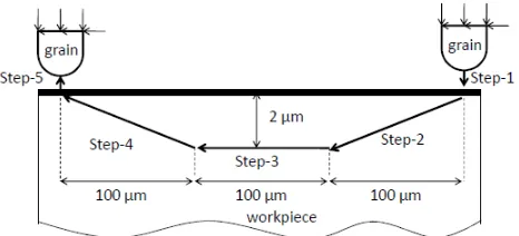
[image:3.595.188.421.525.631.2]A 3D single grit FEM simulation is performed by using ABAQUS/Standard. The abrasive grits are modelled by using CBN (Cubic Boron Nitride) material properties (E=909 GPa, ν=0.121, and ρ=3400 kg.m-3) with a geometrical shape of hemispherical solid with a diameter of 100 µm. Workpiece is modelled with dimensions of 2mm×1mm×0.5 mm by using steel elastic parameters (E=200 GPa, ν=0.3, ρ=7800 kg.m-3) and yield stresses (180, 200, 250, 300 MPa) correspond to plastic strains (0, 0.1, 0.25, 0.3) respectively. The grit cutting path is defined as in Figure 1. The grit and workpiece are modelled by using C3D4 element, which is a four node linear tetrahedron element. Iterative adaptive remeshing technique is used to get finer element size in grit-workpiece engagement area. During simulation, it is necessary to remesh the part when severe mesh distortion takes place. The remeshing technique is based on the refinement and coarsening techniques and avoids entirely remeshing the workpiece. The remeshing is governed by mesh element size and equivalent plastic strain error indicator is used to make decision about satisfaction of element geometry and contact conformity at interaction area. Fine meshes over the cutting area provide better conformity of contact between grit and workpiece. Adaptive remeshing is typically used for accuracy control, although it can also be used for distortion control in some situations. The adaptive remeshing process involves the iterative generation of multiple dissimilar meshes to determine a single, optimized mesh that is used throughout an analysis. The goal of adaptive remeshing is to obtain a solution that satisfies mesh discretization error indicator targets that you set [15].
FIGURE 1. Schematic drawing of grit movement trajectory with a maximum depth of cut 2 µm.
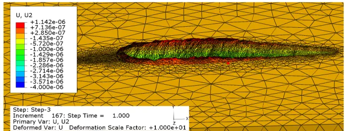
Another essential parameter that affects material removal mechanism change is the friction between grit and workpiece. In this paper, FEM simulation results are interpreted by material deformation and reacting forces during a single grit scratching in relation to the depth of cut and friction coefficient. A result of 3D ploughing deformation is shown in Figure 2 where the frictionless contact and maximum depth of cut of 2µm were used. The maximum material upheaval in front of grit is 1.142 µm which is almost half value of the depth of cut. Deformation scale factor of 10 is applied to make pictorial illustration more obvious. Total number of elements used in the simulation is 184085. Approximate CPU time for each simulation is 42 hours by using a computer with an Intel(R) core(TM) i7 CPU 960 @ 3.20 GHz and 12GB of RAM.
FIGURE 2. A view during grit advancement showing accumulation of workpiece material in front and side of grit (maximum depth of cut is 2 µm and µ=0).
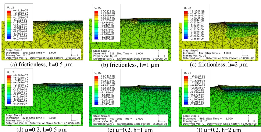
Figure 3 shows the influence of friction on ploughing actions. According to results, the pile-up material height is around half of depth of cut thickness under frictionless condition and is almost the same as the depth of cut when friction coefficient is 0.2. This means friction between grit and workpiece results in increasing ploughed material in grinding. Moreover, edge of piled material under frictional high depth of cut has illustrated the initiation of chip formation phenomenon. Although, under current simulation there is no chip formation due to low depth of cut and low cutting speed.
As shown in Figure 4 Misses stresses during grinding are increasing with the increase of frictional coefficient. The maximum stress observed is in the grit rather than in the workpiece surface and the location of maximum stress point is getting closer to contact surface while friction coefficient increases. Another interesting phenomenon in Figure 4 is that the friction between grit and workpiece affects the stress distribution. When frictionless contact is considered, the stress circle is inclined perpendicular to the contact chord. By considering friction, the stress circle is pushed backwards by an angle that is similar to the friction acting angle. Residual stresses are not changing much with frictional coefficient.
(a) frictionless, h=0.5 µm (b) frictionless, h=1 µm (c) frictionless, h=2 µm
[image:5.595.81.509.94.311.2](d) µ=0.2, h=0.5 µm (e) µ=0.2, h=1 µm (f) µ=0.2, h=2 µm FIGURE 3. Deformation shows ploughing effects on single grit simulation (h: maximum depth of cut).
(a) µ=0
(b) µ=0.2
[image:5.595.82.509.350.461.2]
(c) µ=0.3
FIGURE 4. Stress variations on grit and workpiece with friction effect (depth of cut=1 µm).
(a) (b)
FIGURE 5. Total reacting force in a single grit scratch (a) frictionless, (b) friction coefficient 0.2.
CONCLUSIONS
We can draw the following conclusions from this simplified model of single grit FEM simulation:
[image:5.595.103.489.493.600.2]2- Mesh element size is essential for material removal simulation, since remeshing provides finer mesh size where elements subjected to large deformation due to yielding.
3- Friction also contributes grinding stresses positively. The friction force pushes stress circle incline backwards in an angle similar to friction acting angle. However, residual stresses do not change significantly with friction. 4- Total forces increase with of depth of cut and frictional coefficient.
5- FEM simulation is a powerful technique to predict the grinding behaviours; it saves the time and cost spending on real machining tests.
REFERENCES
1. H.K. Tönshoff, J. Peters, I. Inasaki, T. Paul, Annals of the CIRP 41, 677-688 (1992).
2. E. Brinksmeier, J. C. Aurich, E. Govekar, C. Heinzel, H-W. Hoffmeister, F. Klocke, J. Peters, R. Rentsch, D.J. Stephenson, E. Uhlmann, K. Weinert, M. Wittmann, Annals of the CIRP 55, 667–696 (2006).
3. A.G. J. Kundrák, D.E. Manolakos, K. Gyáni, A. Markopoulos, Int. J. Adv. Manuf. Tech. 21, 929-934 (2003). 4. P.N. Moulik, H.T.Y. Yang, S. Chandrasekar, Int. J. Mech. Sci. 43, 831-851 (2001).
5. D.A. Doman, A. Warkentin, R. Bauer, Int. J. Mach. Tool. Manu. 49, 109-116 (2009). 6. Y. Ohbuchi and T. Obikawa, J. Eng. Mater. and Technol. 125, 324-332 (2003). 7. X. Lai, H. Li, C. Li, Z. Lin, and J. Ni, Int. J. Mach. Tool. Manu. 48, 1-14 (2008). 8. Y. Ohbuchi, T. Obikawa, JSME Int. J C-Mech. Sy. 49, 114-120 (2006).
9. N. Takenaka, Annals of the CIRP 13, 183-190 (1966).
10. T. Matsuo, S. Toyoura, E. Oshima, Y. Ohbuchi, Annals of the CIRP 3, 323-326 (1989).
11. F. Klocke, “Modelling and simulation of grinding processes,” in 1st European conference on Grinding, Aachan 6-7 November, 2003.
12. F. Klocke, T. Beck, S. Hoppe, T. Krieg, N. Müller, T. Nöthe, H-W. Raedt, K. Sweeney, J. Mater. Process. Tech. 120, 450-457 (2002).
13. D.A. Doman, R. Bauer, A. Warkentin, Proc. IMechE Part B: J. Engineering Manufacture223, 1519-1527 (2009).