Railway Security System based on ZIGBEE Technology
Rashmi Sonawane
G.H. Raisoni Institute Of Engineering And Management ,,Maharashtra
EMAIL:
[email protected]
Abstract
A system for preventing trains from derailing and
colliding with hazards on railways is disclose. Railway
safety is a crucial aspect of rail operation the world
over.. This paper is designed at helping the railway
administrations concerned to strengthen their safety
culture and develop the monitoring tools required by
modern safety management. The train and trolley The
CPU calculates the space between the trolley and the
train, rate at which the train is roaming, and the
distance required for the train to stop. The
microcontroller transmit speeding up and deceleration
commands to the trolley and/or train to maintain a
safe distance between the trolley and a train. If the
trolley derail, stop or slow downward due to a hazard
on the railway or another difficulty, the CPU
generates guidelines to slow down or end the train, as
needed, to avoid the train from derailing or colliding
with the trolley or a hazard on the railway. The
wireless communication can be possible using ZigBee
or RF transmitter.
Key Words:
Zig Bee ; RF transmitter;Servo motor.
I Introduction
Railway is lifeline of India and it is being the cheapest modes of transportation are preferred over all other means of transportation. When we go through the daily newspapers we come across many accidents in railroad railings. Railroad-related accidents are more dangerous than other transportation accidents in terms of severity and death rate etc[1]. Therefore more efforts are necessary for improving safety. Collisions with train are generally catastrophic, in that the destructive forces of a train usually no match for any other type of vehicle. Train collisions form a major catastrophe, as they cause severe damage to life and property. Train collisions occur frequently eluding all the latest technology.
Railway safety is a crucial aspect of rail operation the world over. Malfunctions resulting in accidents usually get wide media coverage even when the railway is not at fault and give to rail transport, among the uninformed public, an undeserved image of inefficiency often fueling calls for immediate the railway administrations concerned to strengthen their safety culture and develop the monitoring tools required by modern safety management. Railroad intersections are very unique, special, potentially dangerous and yet unavoidable in the World. Here two different entities with entirely different responsibilities, domains, performances come together and converge for a single cause of providing a facility to the road user. During the normal operation also, there is every possibility of accidents occurring even with very little negligence in procedure and the result is of very high risk. The potential for accidents is made higher as the railways control only half the problem. The other half, meanwhile, cannot really be said to be controlled by one entity, as even though traffic rules and road design standards supposedly exist, the movements of road users are not organized and monitored by one specific entity as rigidly as railmovements. The railway systems of Asia and the Pacific are no exception to this. .
II LITERATURE REVIEW
2 .1 EXISTING SYSTEM
be ineffective as it is not considering any active inputs from existing Railway signaling system, and also lacks two ways communication capability between the trains and the control centers or stations. Later geographical sensors have also been used which makes use of satellites for communication. But the system is costly and complicated to implement. At present laser proximity detector is used for collision avoidance, IR sensors identifies the cracks in the railway track and gate control is done by manual switch controlled gate. But there is no combined solution for collision between trains, train derailment in curves and bends and the automatic control of railway gate.
2.2 PROPOSED SYSTEM
The proposed Train Anti Collision and Level Crossing
Protection System consists of a self-acting
microcontroller and two way ZigBee based data communication system which works round-the-clock to avert train collisions and accidents at the level crosses. Thus enhances safety in train operations by providing a NON-SIGNAL additional safety overlay over the existing signaling system. The system operates without replacing any of the existing signaling and nowhere affects the vital functioning of the present safety systems deployed for train operations. The proposed system gets data from the vibration sensor. The efficiency of the system is expected to be considerably increased as the proposed system takes inputs from the sensor and also from the level crossing gates. As more relevant data are included, it is expected that the present system may assist loco drivers in averting accidents efficiently. As no change is necessary to be made to the infrastructure of the existing system, the cost of implementation of this system is also less. The system has been designed and simulated using proteus real time simulation software.
2.2.1 GENERAL FEATURES
• Railway security and monitoring system mainly focus (i) Train collision avoidance (ii) Derailment in curves and bends (iii) Railway gate control
• This system uses PIC 16F877A microcontroller, PIC 16F73 microcontroller, mini sense 100(v) vibration sensor, zig-bee transceiver, and servo motor.
• PIC 16F877A is an 8 bit microcontroller with 10 channel ADC.
The vibration sensor is used to sense the
vibration of the train.
Servo motor is used for the gate control.
Zig-Bee transceiver provides the
communication between the base station and the train side
Lithium ion battery is used for giving power to
the components.
Regulator IC (LM 7805) used for providing
constant 5v supply
Transistor Tip 122 is used for switching
applications
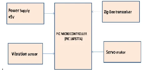
2.2.2 Bolck Diagram
the entire system can be classified into two systems. The first system can be placed in the base station side and the second system can be placed in the train side
• The system in the base station consists, Micro controller (PIC 16f877a), Vibration sensor, Servo motor, zig-bee transceiver and necessary power supply conditions
• The system in the train side consists, Micro controller (PIC 16f73), zig-bee transceiver, Brake control system and necessary power supply conditions
.
Figure 1. Fundamental Block Diagram Of Base Station Side
2.2.3 Block diagram description
The sensors sense the input and sends to the microcontroller, where it responds and gives command to the particular component with predefined algorithm. The time parameters are crucial which can be easily changed and modified using Micro-controllers. Thus, this device would work in coherence would help to reduce the train collisions .
2.2.4 Block diagram components
PIC microcontroller
• The microcontroller is PIC 16F877A and PIC 16f73.
• The microcontroller is used for entire control.
Vibration sensor
• Sense the vibration of the train. According to the vibration it determines the train is arriving or departure.
• It works based on piezoelectric effect. That means it converts mechanical vibration of train into electric pulses
. • The vibration sensor used in our paper is mini sense 100 vertical.
Zig-Bee transceiver
•
Zig-Bee devices are often used in mesh network formto transmit data over longer distances, passing data through intermediate devices to reach more distant ones
. • Zig-Bee is a specification for a suite of high level communication protocols
• The IEEE specification of Zig-Bee is IEEE 802.15.4.
Servo motor
• It is the modified form of DC motor
• It consist DC motor, potentiometer, gearing system.
• The servo motor works based on PWM switching • The main advantage of servo motor is precise control of angular position
III Methodology
3.1 ZIGBEE
The name ZigBee refers to the waggle dance of honey bees after their return to the beehive. It symbolizes the communication between nodes in a mesh network. So it is called as networking protocol. The network components are analogous to queen bee, drones and worker bees. It is also the technological Standard Created for Control and Sensor Networks based on the IEEE 802.15.4 Standard created by the ZigBee Alliance.
ZigBee is a specification for a suite of high level communication protocols using small, low-power digital radios based on an IEEE 802 standard for personal area networks. In the IEEE 802.15.4 standard the 802 refers to the network operations and technologies, refers to wireless networking and to the low data rate or low power consumption
3.2 ZIGBEE DEVICE TYPES
3.2.1 ZigBee Co-coordinator (ZC):
The most capable device, the Co-coordinator forms the root of the network tree and might bridge to other networks. There is exactly one ZigBee Co-coordinator in each network since it is the device that started the network originally (the ZigBee Light Link specification also allows operation without a ZigBee Co-coordinator, making it more usable for over-the- shelf home products). It stores information about the network, including acting as the Trust Center & repository for security keys.
3.2.2 ZigBee Router (ZR):
As well as running an application function, a Router can act as an intermediate router, passing on data from other devices.
3.2.3 ZigBee End Device (ZED):
It Contains just enough functionality to talk to the parent node (either the coordinator or a Router); it cannot relay data from other devices. This relationship allows the node to be asleep a significant amount of the time thereby giving long battery life. A ZED requires the least amount of memory, and therefore can be less expensive to manufacture than a ZR or ZC.
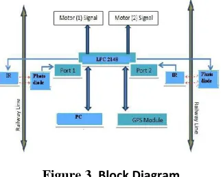
the photo diode and hence the photo diode resistance is high. Subsequently, when the IR light falls on the photo diode, the resistance of the photo diode gets reduced and the amount of reduction will be approximately proportional to the intensity of the incident light. Therefore, when light from the IR deviates from its path due to the presence of a crack or a break, a sudden decrease in the resistance value of the photo diode ensues. This change in resistance indicates the presence of a crack or some other similar structural defect in the rails. In order to detect the current location of the device in case of detection of a crack, a GPS receiver whose function is to receive the current latitude and longitude data is used. To communicate the received information, a PC has been utilized. The function of the PC being used is to upload the current latitude and longitude data to the relevant authority.
Figure 3. Block Diagram
The various components in the block diagram are mentioned below:
1. LPC2148 Microcontroller 2. Power Supply
3. Crystal Oscillator 4. Reset
5. 16x2 Liquid Crystal Display(LCD) 6. MAX 232
1. Microcontroller Unit
The LPC2119/2129/2194/2292/2294 are based on a 16/32 bit ARM7TDMI-STM CPU with real-time emulation and embedded trace support, together with 128/256 kilobytes (kB) of embedded high speed flash memory. A 128-bit wide internal memory interface and a unique accelerator architecture enable 32-bit code execution at maximum clock rate. For critical code size applications, the alternative 16-bit Thumb Mode reduces code by more than 30% with minimal performance penalty. Features of the microcontroller:
1. It is a 32-bit microcontroller.
2. 256K Bytes of In-System Programmable (ISP) Flash Memory.
3. 4Kx 32-bit Internal RAM. 4. 46 Programmable I/O Lines. 5. Two 32-bit Timer/Counters. 6. On chip ADC and DAC. 7. 2 UART Serial Channels.
2. Power Supply
The input to the circuit is applied from the regulated power supply. The microcontroller voltage is of 5V. The A.C. input i.e., 230V from the mains supply is step down by the transformer to 12V and is fed to a rectifier. The output obtained from the rectifier is a pulsating D.C voltage. So in order to get a pure D.C voltage, the output voltage from the rectifier is fed to a filter to remove any A.C components present even after rectification. Now, this voltage is given to a voltage regulator to obtain a pure constant dc voltage. We are using an IC 7805 as voltage regulator to get a 5V output Voltage.
3.Crystal Oscillator
A crystal oscillator is an electronic oscillator circuit that uses the mechanical resonance of a vibrating crystal of piezoelectric material to create an electrical signal with a very precise frequency. This frequency is commonly used to keep track of time (as in quartz wrist watches), to provide a stable clock signal for digital integrated circuits, and to stabilize frequencies for radio transmitters and receivers. The most common type of piezoelectric resonator used is the quartz crystal, so oscillator circuits designed around them became known as “crystal oscillators”. This block provides necessary frequency sine wave to the micro controller.
4. Reset
Control reset is to execute the entire program cycle from beginning.
5. MAX232
The microcontroller can communicate with the serial devices using its single serial port. The logic levels at which this serial port operates is TTL logics. But some of the serial devices operate at RS 232 logic levels. So in order to communicate the microcontroller with modem, a mismatch between the logic levels occurs.
6. Global Positioning System (GPS)
any weather conditions anywhere in the world for free. GPS was formally known as the NAVSTAR (Navigation Satellite Timing and Ranging). The basis of the GPS technology is a set of 24 satellites that are continuously orbiting the earth. These satellites are equipped with atomic clocks and sent out radio signals as to the exact time and location. These radio signals from the satellites are picked up by the GPS receiver. Once the GPS receiver locks on to four or more of these satellites, it can triangulate its location from the known positions of the satellites. It is a higher performance, low power satellite based model. It is a cost effective and portable system which accurately detects the location. The GPS receiver used here is Sky Traq Venus 6 GPS module ST22 which is having TTL logics and also RS232 as option. The GPS receiver is shown in Fig.5. This GPS is used to track the position of the train after the emergency brake is applied in order to avoid the accidents. GPS Receiver Specifications:
1. 65 channels-1Hz Update rate 2. Hot Start- 1sec
3. Baud rate- 9600bits/s 4. Operating Voltage-5Volts dc 5. O/P Format-NMEA 0183-RS232 6. Operating Temperature: -40 to +85oC 7. Sensitivity- Tracking: -160 dBm
Figure.4: GPS Receiver
H. DC Motors To traverse a distance of 22 Km in 4 hrs, an average speed of 1.5 meters/sec is needed. The proposed design uses 4 DC motors (Torque Rating: 10Kg and Speed Rating: 500 rpm) interfaced with the LPC 2148 With a wheel diameter of 5.2 cm and the total mass of around 5 Kg the approximate speed of the robot is around 0.5 metres/sec. Hence it has been calculated that three such robots would be required to scan the whole Railway System.
I. IR-Photo diode Assembly
The common 5V IR and Photo diode was found to be sufficient. The IR is powered using one of the digital pin of the LPC 2148. The photo diode and a 45kΩ resistor form a potential divider arrangement. The output of the potential divider is given to one of the analog input channel of the LPC 2148.
IV Result
Whenever the IR light falls on the photo diode the GPS receiver receives the current latitude and longitude data. by using a software which is installed in PC the received latitude and longitude data are sent to PC which will upload this value
values as shown in figure
The webpage contains the information about the time when it is received and latitude and longitude :
IV CONCLUSION
Collision avoidance systems are especially useful in bad weather conditions. In this paper, a design for automatically averting train collisions and accidents at level crossing gate have been designed, simulated and tested.
• It uses the advanced features of pic micro controller with vibration sensor and zigbee communication technique, proves to be effective in achieving the objects
• It is applicable at every aspect of the railways for uninterruptible service
• Saving human life, protection against accidents and the communicable electronic systems are the salient features and the added advantage of this project.
structure as well as the expenditure on attendant it is more economical at above mentioned places than traditional railway crossing gate system. We know that though it is very beneficial but it is also impossible to install such system at each and every place, but it gives certainly a considerable benefit to us, thereby to our nation.
V FUTURE SCOPE
As future expansion it is proposed that licensing procedures of satellite communications may be initiated so as to implement a system upgrade whereby real time data of moving trains like speed and current location may be tracked and monitored at the control station. Such real-time information can be utilized for system upgrade so as to avert accidents due to natural calamities such as land slide and cyclone. An additional geographic sensors and interface with geographic information system may be required for the same. Panic buttons may be provided in all compartments of the train which may be used by passengers in case of danger and alert the control station. Algorithm of the proposed system may also be altered so as to incorporate a cruise control such that whenever speed of train is detected to be higher than a rated level automatic brake may be
applied. Automatic slowdown of trains when
approaching stations without stops may also be implemented as per requirements from Indian Railways. Anti collision device is a self acting microprocessor based data communication device designed and developed by Konkan Railway (KR). When installed on locomotives, guard vans, stations and level crossing gates. The network of ACD systems prevents high speed head on collisions in mid sections, station areas and at level crossing gates, thereby saving the lives of rail passengers and road users. This device can be integrated with the Anti collision device for better sophistication and optimization.