Design and simulation of Wind formsfor Grid
Connected system usingInductive Filtering Fed
Industrial Applications
Shaik Mahaboob SubhaniM-tech Student Scholar
Department of Electrical & Electronics Engineering, Loyola Institute of Technology & Management, Dhulipalla, Loyola Nagar, Sattenapalli (M), Guntur (Dt);
A.P, India.
Kopalle. Ashoka Babu, (M.Tech) Assistant Professor
Department of Electrical & Electronics Engineering, Loyola Institute of Technology & Management, Dhulipalla, Loyola Nagar, Sattenapalli (M), Guntur (Dt); A.P,India.
Abstract-The wind turbine generator system requires a power conditioning circuit called power converter that is capable of adjusting the generator frequency and voltage to the grid. Several types of converter topologies have been developed in the last decades; each of them has some advantages and disadvantages. Mainly two converter topologies are currently used in the commercial wind turbine generator systems. Nonlinear loads cause significant harmonic currents with poor input power factor (PF), which create serious problems at the power supply system. However, the parallel and the series resonance could occur between TIF and grid impedance a STATCOM model is also developed. Simulation studies are carriedout in the Dig silent/Power factory to illustrate the performance ofthe new grid connected wind power system. The results indicatethat the new approach can not only enhance the low-voltageride-through capability of wind turbines, but also significantlyprevent harmonic components flowing into the primary (grid)winding of the new grid connected transformer.Distribution system, as the name suggest, is the medium through which power is distributed among the end consumers Distribution systems are comparatively not as stiff as grid systems, so large starting currents and objectionable voltage drop during the starting of an induction motor could be critical for the entire system. Thus STATCOM is an effective solution for power systems facing such power quality problems. This report deals with one of the potential applications of static compensator (STATCOM) to industrial systems formitigation of voltage dip problem. The dip in voltage is generally encountered during the starting of an induction motor.
Keywords—Inductive filtering method; STATCOM; grid connected system; wind farm, Induction motor.
I. INTRODUCTION
Centralized power generation systems are facing the twin constraints of shortage of fossil fuel and need to reduce the e missions. Long distance transmission line are one of the main causes for electrical power losses. So, emphasis has increased on distributed generation (DG) networks with integration of renewable energy systems into the
national grid, which lead to efficiency and reduction in emissions [1-2]. With the rise of the renewable energy penetration into the grid, power quality of low voltage power transmission system is becoming a major area of interest. Most of available integration of renewable energy systems to the grid takes place with the aid of power electronics converters. The primary use of the power electronic converters is to integrate the DG to the grid in compliance with power quality standards [3]. But, high frequency switching of inverters can inject more harmonics to the systems, creating major PQ problems if it is not implemented properly.
Filtering methods like Hybrid Filtering (Combination of series passive and shunt Active Power Filter) &Inductively Active Filtering are the latest development of interfacing devices between distribution supply (grid) and consumer appliances to overcome voltage/current disturbances and improve the power quality by compensating the reactive and harmonic power generated or absorbed by the load [4-5].
Solar is the one of most promising DG sources and their penetration level to the grid is on the rise. Although the advantage of Distributed generation includes voltage support, decrees in transmission & distribution losses and improved reliability. PQ problems [6] are also of growing concern. This paper deals with a research and development of PQ problems related to solar integrated to the grid and the impact of poor power quality. The connection topologies of filtering into the system to overcome the PQ problems are also discussed [7].
fixed compensation, possibility of resonance etc., the use of new compensators such as STATCOM is growing to solve power quality problems. The use of STATCOM for solving power quality problems due to voltage sags, flickers, swell etc has been suggested. The purpose of STATCOM is to provide efficient voltage regulation during short duration of induction motor starting and thus prevent large voltage dips [8-9].
II.Main Circuit Topology of the New Grid Connecte d Wind Powe r Syste m
Fig.1. Main circuit topology of the grid connected wind power system.
Fig.1 shows the main circuit topology of the grid connected wind power system. From this, it can be seen that it is a 50 MW wind farm composed of 25 double-fed induction generators (DFIGs), and each DFIG has a rating of 2 MW. Each wind turbine is connected to the wind farm internal 35 kV cable network via a 2.2 MVA, 0.69/35 kV transformer. The wind farm is connected to the power grid by means of a new grid-connected transformer, which has the grid winding, the secondary winding and the filtering winding, respectively. The FT branches and STATCOM are connected to the filtering winding of the new grid-connected transformer. The point of common coupling (PCC) voltage should be regulated at the 110 kV.
III. HARMONIC MODEL AND EQUIVALENT CIRCUIT MODEL
To study the filtering mechanis m of the inductive method, the single-phase equivalent circuit model of the new grid connected transformer is established as shown in Fig.2, in which, the VSC-based wind turbine generators can be regarded as the voltage source. The harmonic current in the grid winding, secondary winding and filtering winding are the I1n, I2n and I3n respectively.
Fig.2. the single-phase equivalent-circuit model of the new grid connectedtransformer with FT branches.
According to Fig.2, the equations of the harmonic current and voltage can be obtained:
(1) Moreover, the magnetic-potential balance equation can be expressed as follows:
(2) Where N1, N2, N3 are the numbers of turns of the grid winding, the secondary winding and the filtering winding respectively. Then, according to the theory of the multi-winding transformer, the voltage transfer equations can be obtained:
(4) There are no harmonic current in the primary winding of the new grid connected transformer, thus we can obtain U1n≈0. According to the mathematic model, the current
in the primary winding of the new grid connected transformer can be expressed as follows:
(5) From equation (5), it can be seen that as long as the Z3n and Z fn approximately equal or equal zero, the condition of the inductive filtering method can be satisfied. Thereby, there is no or few harmonic current in the grid (primary) winding, which reveals the filtering mechanis m of the new grid connected transformer and related FT branches. Moreover, the special impedance design of the new grid connected transformer can make the equivalent impedance of the filtering winding (Z3n) approximately equal zero.
IV. REACTIVE POWER COMPENSATION CHARACTERISTIC
A. Phasor Analysis
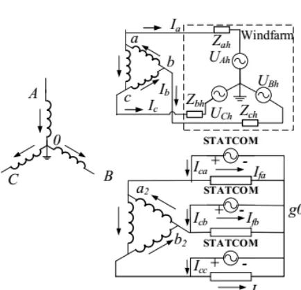
In the new grid connected wind power system, FT branches and STATCOM can support voltage stability by compensating reactive power. According to the current distribution in the new grid connected transformer, as shown in Fig.3, we can obtain the phasor diagra m of the secondary winding’s voltage and current of the new grid connected transformer, as shown in Fig.4.
Fig. 3. The current distribution of the new grid connected transformer.
Taking the A-phase winding in Fig.4 as an example, assume the secondary winding current Ia lags the phase of
the secondary winding voltage Ua by δ. Since the
impedance of the FT branches is capacitive for the funda mental, when we carry out the FT branches and STATCOM, the phase current of the FT branches will lead 90º to the secondary winding voltage Ua. In addition, the currents Ica that the STATCOM injected lags the phase of the secondary winding voltage UA by 90º, also. Thus, we can obtain that the angle of the load-side I′ a
(with the inductive filtering method and STATCOM) lags the secondary winding voltage Ua is smaller than δ.
Fig.4 Phasor diagram of the voltage and current of the secondary winding.
B. Control Scheme of STATCOM
The STATCOM and its controller are shown in Fig.5. It connects the filtering winding and can improve transient stability of power grid (Vac).
Fig.5. Schematic diagram of STATCOM controller.
The STATCOM regulate voltage of the grid winding of the new grid connected transformer by controlling the reactive power injected into or absorbed from the power grid. In the Fig.5, an outer regulation loop contains an ac voltage regulator and a dc voltage regulator, while an inner regulation loop contains a current regulator. The control signal of STATCOM (e.g. Vd, Vq) can be obtained by the regulator loop and they are usually used by the PWM module to generate the pulse signals to drive IGBT of the STATCOM.
The objective of the STATCOM is primarily to keep the ac voltage constant. During the nor mal conditions, the grid voltage is stability and the reactive power flow from or to STATCOM is approximately zero. When the grid is under fault conditions, The STATCOM will inject a mount of reactive power for the system instantly. Hence, this voltage control strategy reacts immediately to a sudden voltage variation and is well-suitable for fault condition operation in the grid connected wind power syste m.
V.INDUCTION MOTOR
Induction Motor (1M) An induction motor is an example of asynchronous AC machine, which consists of a stator and a rotor. This motor is widely used because of its strong features and reasonable cost. A sinusoidal voltage is applied to the stator, in the induction motor, which results in an induced electromagnetic field. A current in the rotor is induced due to this field, which creates another field that tries to align with the stator field,
causing the rotor to spin. A slip is created between these fields, when a load is applied to the motor.
Compared to the synchronous speed, the rotor speed decreases, at higher slip values. The frequency of the stator voltage controls the synchronous speed. The frequency of the voltage is applied to the stator through power electronic devices, which allows the control of the speed of the motor. The research is using techniques, which implement a constant voltage to frequency ratio. Finally, the torque begins to fall when the motor reaches the synchronous speed. Thus, induction motor synchronous speed is defined by following equation,
=
Where f is the frequency of AC supply, n, is the speed of rotor; p is the number of poles per phase of the motor. By varying the frequency of control circuit through AC supply, the rotor speed will change.
Fig.6.Speed torque characteristics of induction motor.
VI.THE THREE-LEVEL NPC VSI
The diode-clamped inverter [5] was also called the neutral-point clamped (NPC) inverter because when it was first used in a three-level inverter the mid-voltage level was defined as the neutral point level.
A three-level diode-clamped inverter is shown in Fig. 7. In this circuit, the dc-bus voltage is split into three levels by two series-connected bulk capacitors, C1 and C2. The middle point of the two capacitors N can be defined as the neutral point. The output voltage VAN has three states: Vdc/2, 0, and -Vdc/2. For voltage level Vdc/2, switches S1 and S2 need to be turned on; for -Vdc/2, switches S'1 And '2s need to be turned on; and for the 0 level, 2s and S'1 need to be turned on. The two diodes D5 and D6 clamp the switch voltage to half the level of the dc-bus voltage. When both 1s and 2s turn on, the voltage across A and O is Vdc, i.e., VAO = Vdc. In this case, D6 balances out the voltage sharing between S'1 and S'2 with S'1 blocking the voltage across C1 and S'2 blocking the voltage across C2.
Some of the important features of diode clamped inverter are given below: Low voltage power semiconductor devices: The m-level diode clamped inverter requires (m+1) active devices (GTO and IGBT’s etc) per phase and each active device will see a blocking voltage of (Vdc / (m-1)).
Duty cycle of switching devices: The duty cycle of the power switches is different. So switches of different current rating have to be used for optimal design.
(a) Rating for clamping diodes: For five and higher level inverters, the voltage blocking capability of the diodes are different. So the diodes will have different voltage ratings. Assuming that the characteristics of diodes are identical, then multiple diodes of same voltage rating have to be used to achieve required voltage-blocking capacity. Hence, for a sufficiently large number of levels, the number of diodes required will become too large and will make the circuit less reliable. Also power circuit layout and packaging becomes difficult.
(b) Capacitor voltage unbalance: The midpoint voltage is derived using capacitors and these carry load current. Unequal loading of the capacitors leads to imbalance in the dc bus capacitor voltages and this will cause the dc mid pint voltage to drift. This is not a serious problem for utility applications such as, static VAR generators (SVG), active power filters, etc., where the inverters need to supply only the reactive power.
(c) High voltage surge: During turn off, the devices will experience a high transient over voltage and also snubbers are required to distribute the voltage across cla mping diodes in a uniform fashion. The design of snubbers is complicated, as the current through these snubbers is bi-directional.
When the number of output levels is sufficiently high, the inverter system required a huge number of cla mping devices due to the series connection of clamping diodes and capacitors. These not only increase the cost of the system, but also controlling the inverter output and capacitor voltage balance becomes more complex when the number of levels is higher than five. Thus diode clamped inverters are usually limited to three or (maximum).
VII.MATLAB/SIMULATION RESULTS
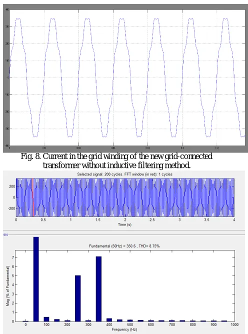
Fig. 8. Current in the grid winding of the new grid-connected transformer without inductive filtering method.
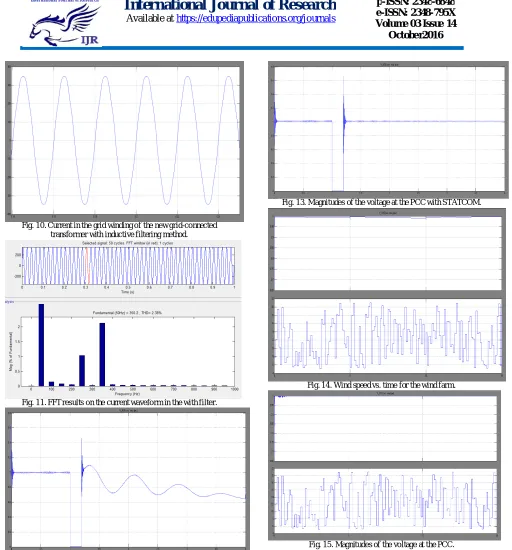
Fig. 10. Current in the grid winding of the new grid-connected transformer with inductive filtering method.
Fig. 11. FFT results on the current waveform in the with filter.
Fig. 12. Magnitudes of the voltage at the PCC without STATCOM.
Fig. 13. Magnitudes of the voltage at the PCC with STATCOM.
Fig. 14. Wind speed vs. time for the wind farm.
Fig.16.Matlab/Simulation model of Main circuit topology with induction motor drive.
Fig.17.phase to phase voltage three level inverter.
Fig.18.Line to Line Voltage of the Three Level Inverter.
Fig.19.Stator Current, Speed and Electromagnetic Torque of Induction Motor.
VIII. CONCLUSIONS
A model of three phase source feeding motor loads has been developed using Simulink tool of standard MATLAB software. Sudden application of an induction motor load results in large starting currents which results in sudden dip in ac terminal voltage at PCC The extent of voltage dip with and without STATCOM controller. This dip is very large and it may affect the functioning of other sensitive equipment connected at PCC Model of STATCOM system applied in shunt configuration has been developed The STATCOM control utilizes two PI controllers for regulating DC link voltage and also the ac terminal voltage at PCC. The simulation results indicate that the new approach not only can significantly improve the filtering performance, but also effectively reduced the level of voltage fluctuation when the wind speed varies in a large range. Moreover, the new approach can successfully reestablished the PCC voltage in case of the grid fault, and therefore, enhanced the low-voltage ride through capability of the wind farm.
REFERENCES
[1] D. Dhungana and R. Karki, “Data constrained adequacy assessment for wind resource planning,” IEEE Trans. Sustrain. Energy.,Vol 6, no. 1, pp: 219-227, Jan. 2015.
[2] A. Haque, M. Nehrir and P. Mandal, “A hybrid intelligent model for deterministic and quantile regression approach for probability wind power forecasting” IEEE Trans. Power Syst.,Vol 29, no. 4, pp: 1663-1672, Jul. 2014.
[3] M. Zugno, P. Pinson and H. Madsen, “Impact of wind po wer generation on european cross-border power flows,” IEEE Trans. Power Syst.,Vol 28, no. 4, pp: 3566-3575, Nov. 2013.
[4] L. Shun, Q. Hu and W. Lee, “A survey of harmonic emissions of a commercially operated wind farm,” IEEE Trans. Ind. Appl.,Vol 48, no. 3, pp: 1115-1123, May. 2012.
terminal HVDC transmission,” IEEE Trans. Ind. Appl.,Vol 50, no. 4, pp: 2788-2797, Jul/Aug. 2014.
[6] S. W. Mohod and M. Aware “A STATCOM-control scheme for grid connected wind energy system for power quality improvement,” IEEE Trans. Syst. Journal.,Vol 4, no. 3, pp: 346-352, Sep. 2010.
[7] W. Li and D. Truong, “Dynamic stability improvement of four parallel-operated PMSG-based offshore wind turbine generators fed to a power system using a STATCOM,” IEEE Trans. Power. Del.,Vol 28, no. 1, pp: 111-118, Jun. 2013.
[8] K. Hasan, K. Rauma, A. Luna, J. Candela and P. Rodríguez, “Harmonic compensation analysis in offshore wind power plant using hybrid filters,” IEEE Trans. Ind. Appl.,Vol 50, no. 3, pp: 2050-2060, May/Jun. 2014.