EFFICIENT SMART ANTENNA FOR 4G
COMMUNICATIONS
1
Saloni Aggarwal,
2Neha Kaushik,
3Deeksha Sharma
1,2,3
UG, Department of Electronics and Communication Engineering,
Raj Kumar Goel Institute of Technology for Women, UP (India)
ABSTRACT
The Fourth Generation (4G) Mobile Communications focuses not only on the data-rate increase but also on
new air interface. In this paper 4G Mobile con-verges the advanced wireless mobile communications and
high-speed wireless access systems into an Open Wireless Architecture (OWA) platform which becomes the core of
this emerging next generation mobile technology. 4G provides high data rates, spectral density, fast mobility
and also integration. Orthogonal Frequency Division Multiplexing (OFDM) is proving to be a possible multiple
access technology which can be used in 4G. OFDM has its own drawbacks like high Peak to Average Ratio,
linearity concerns and phase noise which is solved by clipping. Multiple antennas are employed at the base
station. Multiple antennas are used for beam diversity, multiple combining, range improvement, low
interference etc. for obtaining high performance thus leading to the concept of Smart Antennas.
Keywords: OFDM, OWA Architecture, Signal Combining Technique, Smart Antennas.
I. INTRODUCTION
1.1 Antenna Basics
Smart antennas are arrays of antenna elements that change their antenna pattern dynamically to adjust to the
noise, interference and mitigate multipath fading effects on the signal .The secret to the smart antenna is the
ability to transmit and receive signals in an adaptive spatially sensitive manner is the digital signal processing
capability present.
1.2 Classification
On the basis of their transmit strategy, they are classified into the following three types-
1. Switched Beam Antennas
2. Dynamically-Phased Arrays
3 .Adaptive Antenna Arrays
Switched Beam Antennas-Switched Beam Antennas are directional antennas deployed at base station
of a cell. They have only a basic switching function between separate directive antennas or predefined
Dynamically-Phased Arrays-In Dynamically Phased Arrays; a direction of arrival algorithm tracks
the user signal as he roams within the range of the beam that’s tracking him.
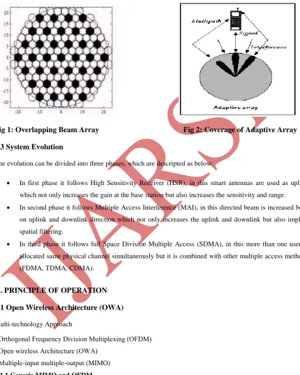
Adaptive Antenna Arrays-An Adaptive Antenna Array is a set of antenna elements that can adapt their antenna pattern to changes in their environment.Fig 1: Overlapping Beam Array Fig 2: Coverage of Adaptive Array
1.3 System Evolution
The evolution can be divided into three phases, which are descripted as below:
In first phase it follows High Sensitivity Receiver (HSR), in this smart antennas are used as uplink
which not only increases the gain at the base station but also increases the sensitivity and range.
In second phase it follows Multiple Access Interference (MAI), in this directed beam is increased both
on uplink and downlink direction which not only increases the uplink and downlink but also implies
spatial filtering.
In third phase it follows full Space Division Multiple Access (SDMA), in this more than one user is
allocated same physical channel simultaneously but it is combined with other multiple access methods
(FDMA, TDMA, CDMA).
II. PRINCIPLE OF OPERATION
2.1 Open Wireless Architecture (OWA)
Multi-technology Approach
• Orthogonal Frequency Division Multiplexing (OFDM) • Open wireless Architecture (OWA)
• Multiple-input multiple-output (MIMO)
2.1.1Generic MIMO and OFDM
Multiple antenna technologies enable high capacities suited for Internet and multimedia services and also
dramatically increase range and reliability. The target frequency band for this system is 2 to 5 GHz due to
OFDM is chosen over a single carrier solution due to lower complexity of equalizers for high delay spread
channels and high data rates. A broadband signal is disintegrated into multiple narrowband carriers (tones),
where each carrier is more robust to multipath. In order to maintain orthogonally amongst signals, a cyclic
prefix is additive which is greater in length. OFDM can be implemented efficiently by using FFT's at the
transmitter and receiver .At the receiver, FFT reduces the channel response into a multiplicative constant on a
tone-by-tone basis .With MIMO, the channel response becomes a matrix. Since each tone can be equalized and
complexity of space time equalizers is avoided. Multipath remains an advantage in a MIMO-OFDM system
since frequency selectivity caused by multipath improves the rank distribution of the channel.
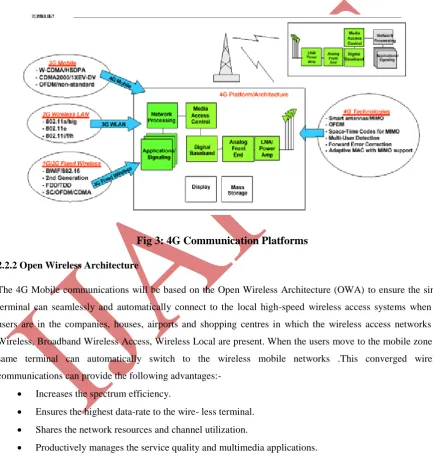
Fig 3: 4G Communication Platforms
2.2.2 Open Wireless Architecture
The 4G Mobile communications will be based on the Open Wireless Architecture (OWA) to ensure the single
terminal can seamlessly and automatically connect to the local high-speed wireless access systems when the
users are in the companies, houses, airports and shopping centres in which the wireless access networks i.e.
Wireless, Broadband Wireless Access, Wireless Local are present. When the users move to the mobile zone the
same terminal can automatically switch to the wireless mobile networks .This converged wireless
communications can provide the following advantages:-
Increases the spectrum efficiency.
Ensures the highest data-rate to the wire- less terminal. Shares the network resources and channel utilization.
Productively manages the service quality and multimedia applications.
Figure 3 shows the wireless evolution to 4G mobile communications based on OWA platform, in which 3G,
wireless LAN and wireless access technologies will be converted into 4G mobile platforms to deliver the best
infrastructure of mobile communications with optimal spectrum efficiency and resource management.
Selection Diversity-this is a quite simple approach for combining signals if the receiver has to process
multichannel simultaneously. Receiver simply switches to the channel which has the highest signal
power.
Ratio Combining- This technique is used to maximize the SINR of the combined signals when
interference on each multichannel is uncorrelated.
Non coherent Combining-if the receiver employs detection, the carrier phase reference is simply the
data samples obtained for the previous symbol.
Wiener Filtering—it attempts to suppress the interference and maximize the SINR at the combined
output. Other three techniques discussed are based on maximizing the signal power at the combined
output.
III. SMART ANTENNA RECIEVER
Two approaches should be considered for combining the data samples.
1D RAKE Filter—it is used for non-coh-rent combining of P channel taps in a single antenna CDMA
receiver.
2D Rake Filter- it is a more effective and compact approach to dealing with the channel tap vectors is
to apply a spatial filter to each tap vector. This permits the receiver to perform coherent combining of
the tap vector elements and improving performance over the 1D RAKE filter. This approach is called
“2D RAKE Filter “because the receiver operates two separate sets of combiners in time and space.
Receiver picks up the largest channel taps and selects appropriate spatial filter in each case, and output
from the filter banks are combined in a conventional RAKE filter ready for making decisions. Base
stations are disintegrated into three sectors, to provide 120 degree coverage.
IV. COMPUTATIONAL ALGORITHMS FOR COMPUTING THE OPTIMUM WEIGHTS
AT THE RECEIVER
All the techniques mentioned in this paper are blind techniques, i.e. they or inverse matrices. All these
algorithms apply the weight vectors after PN-processing to exploit the advantage of DS-CDMA over other
systems. The direction of arrival angles of N users and L multipath are assumed to be independent. Channel
estimation is done using pilot channels. The smart antenna adaptation rate is assumed to be equal to the symbol
rate. Finally, while a real system might use a Viterbi decoder for soft-decision.
The smart antenna algorithms are briefly described below –
Smart Antenna based on Maximum Output Power with Lagrange Multiplier-If the power of the
undesired user is higher than that of the desired user, then this algorithm might end up tracking the
undesired user leading to higher BER. The computational load of the smart antenna is on the order of O
(4M).
Smart Antenna Based on Maximum SINR Output with Eigenvector Solution – In this method, the
antenna array response vector is estimated as the eigenvector with maximum eigenvalue of the matrix
[(Rxx (k) – Ryy (k)], where Rxx is the autocorrelation of the desired signal and Ryy is the
Smart Antenna Based on Maximum SINR Output without Eigenvector Solution – This algorithm
also uses the maximum SINR criteria. However, it does so without calculating any eigenvectors
autocorrelation matrices are updated.
V. ADVANTAGES
Co-Channel Interference- Antennas by the property of spatial filtering focuses radiated energy in the
form of narrow beams in the direction of the desired mobile user.
Range Improvements- Since smart antennas employs collection of individual elements in the form of
an array they give rise to narrow beam with increased gain when compared to conventional antennas
the increase in gain leads to increase in range and the coverage in the system. Therefore lesser number
of base stations is required to cover a given area.
Increase In Capacity - Smart antennas enables reduction in other channels, which results in increase
in the frequency reuse factor.
Reduction In Transmitted Power -Ordinary antennas radiate energy in all directions leading to
wastage in power. Comparatively smart antennas radiate energy only in the desired direction.
Therefore less power is required at the base station.
Reduction in Handoff -. Using smart antennas at the base station, the capacity is increased by using
independent spot beams .So; the handoffs occur rarely that is when frequency crosses each other.
Multipath Effects-Smart antennas can reject multipath components as interference, thus reducing its
effects in terms of fading or it can use the multipath components and add them constructively to
enhance system performance.
Compatibility- Smart antenna technology is applied to various multiple acconents and constructively
enhances system performance.
VI. APPLICATIONS
Smart Antenna is used in number of fields. It has number of Applications. Some of the fields where Smart
Antenna are used:
Mobile Communicaion. Wireless Communication. Radar.
SonarVII. CONCLUSIONS
The newcomer fourth-generation tries to solve this problem by integrating all different wireless technologies
services and contents made available to users. Smart Antenna technology has been introduced which is used for
reducing interference. Use of switched beam and adaptive antenna arrays has been discussed to mitigate
interference and multi path effects while increasing coverage and range.Different Signal combining techniques
the paper smart antenna technology can be used for numerable applications in wireless communication like in
MIMO systems, mobile communication etc.
REFERENCES
[1] Schiller, J., “Mobile Communications”.
[2] Sadiku “Elements of Electromagnetics”, 4th Edition, Oxford University Press.