Copyright to IJAREEIE 10.15662/ijareeie.2015.0402004 524
A novel method for detecting optimal location
and parameters of power system stabilizer
(PSS) based on intelligent techniques
E.Saadati
1, A.Damaki
2, S.Radman
3Senior Student, Dept. of ECE, Yazd University, Iran 1&3
Assistant professor, Dept. of ECE, Yazd University, Iran 2
ABSTRACT:This paper presents a new technique to design a Power System Stabilizer (PSS) in multi-machine power system. The method is based on the Particle Swarm Optimization (PSO) algorithm for tuning PSS parameters including lead-lag compensator time constants as well as the controller gain. For evaluating the particles evolution throughout the searching process, an eigenvalue-based multi-objective function is used. The DIgSILENT is used as tool for modelling test system and programming PSO algorithm. Then by using a fuzzy approach implemented in Matlab/fuzzy toolbox the optimal number and location for PSSs specified. Two-area (four-machine 11bus) Power system is considered as the case study in this paper. Simulation results for various operating conditions prove the capability of the proposed algorithm in damping improvement of power system.
KEYWORDS: Power System Stabilizer, Particle Swarm Optimization, Low Frequency Oscillations, Multi Machine,
Digsilent, Matlab
I.INTRODUCTION
The extension of interconnected power systems is continually increasing because of the constantly growth in electric power demand. Due to the increasing electrical power system demand and need to power systems operate close to their stability limit, modern power systems can reach the stressed conditions more easily than the past. In this situations occurrence of any contingency or disturbance may lead to instability or poorly damped oscillations [1]. Low-frequency oscillations in a power system is the cause of many undesirable effects such as constraining the power transfer on the transmission lines, initiating and propagating stress in the mechanical shaft, endangering the system’s security, and reduce the overall operating efficiency of a power system[2,3]. These oscillations may sustain and grow to cause system separation if no adequate damping is available [4,5].
In the last decades, power system stabilizers (PSSs) have been used by utilities in real power systems as they have proven to be the most cost-effective electromechanical damping control [6]. Many researchers have posed techniques for designing PSSs to enhance the damping of electromechanical oscillations of power systems and improve power systems stability. The most important aspects for designing such a controller are the proper choosing of stabilizer’s feedback signals, the optimal parameter setting and the proper selection of controller’s location [7].
Copyright to IJAREEIE 10.15662/ijareeie.2015.0402004 525
Like other optimization techniques, Particle Swarm Optimization (PSO) is widely used to robust PSS design problem [1,7]. In [13] PSS parameters have optimized by PSO for single machine connected to infinite bus power system to stabilize the system. In order to find the optimal location of PSS, an improved PSO (IPSO) based on the chaotic sequence (IPSOC) is proposed in [14]. However most of previous papers usually a certain number of PSS and/or fixed location have been studied in the PSS design procedure.
In this paper PSS parameters are tuned by using PSO algorithm where the objective function is formulated as an eigenvalue-based multi-objective function comprising both the damping ratio and the real part of the oscillatory mode. Then the best location and optimal number of PSSs is defined by a fuzzy approach. The paper is organized as follows: in Section II, power system model and PSS controller structure is explained and discussed. Particle Swarm Optimization and its advantages over other optimization techniques is studied in Section III and the objective function is presented and explained in Section IV. Next, the Fuzzy approach that is employed for finding best location and optimal number of PSS discussed in Section V. Next, the proposed algorithm is applied to the considered system and simulation results are discussed in Section VI. Finally, conclusions are presented in Section VII.
II. PROBLEM STATEMENT
Power system model: Two Area Four Machine (TAFM) power system is considered as the case study in this paper. The single line diagram of TAFM power system is shown in Fig. 1. The system contains eleven buses and two areas, connected by a weak tie between bus 7 and 9 which causes to suggest for low frequency oscillatory (LFO) stability studies. This power network is specially designed to study low frequency electromechanical oscillations in two interconnected power systems [1]. Totally two loads are applied to the system at bus 7 and 9. Two shunt capacitors are also connected to bus 7 and 9 as shown in the figure below. The detail system data has been taken from [15].
Fig.1 The single diagram of Two Area Power System
The generators are modelled by the sixth order model so has six state variables with the following equations:
𝛿
̇
𝑖= 𝜔
𝑟𝑖− 𝜔
𝑏𝑖(1)
𝜔
̇
𝑟𝑖= (𝑃
𝑚𝑖− 𝑃
𝑒𝑖− 𝐷
𝑖(𝜔
𝑟𝑖− 1)) 𝑀
⁄
𝑖(2)
𝑒
̇
𝑞𝑖 ′=
(
−𝑒𝑞𝑖′ − (𝑥𝑑𝑖− 𝑥𝑑𝑖′ − 𝑇𝑑𝑜𝑖′′ 𝑥𝑑𝑖′′𝑇𝑑𝑜𝑖′ 𝑥 𝑑𝑖
′ (𝑥𝑑𝑖− 𝑥𝑑𝑖
′ ))𝑖
𝑑𝑖
)
⁄
𝑇𝑑𝑜𝑖′(3)
𝑒
̇
𝑑𝑖 ′=
(
−𝑒𝑑𝑖′ − (𝑥𝑞𝑖− 𝑥𝑞𝑖′ − 𝑇𝑞𝑜𝑖′′ 𝑥𝑞𝑖′′𝑇𝑞𝑜𝑖′ 𝑥𝑞𝑖′
(𝑥𝑞𝑖 − 𝑥𝑞𝑖′ ))𝑖𝑞𝑖
)
⁄
𝑇𝑞𝑜𝑖′(4)
𝑒̇𝑞𝑖′′ =(−𝑒𝑞𝑖′′ + 𝑒𝑞𝑖′ − (𝑥𝑑𝑖′ − 𝑥𝑑𝑖′′ + 𝑇𝑑𝑜𝑖′′ 𝑥𝑑𝑖′′
𝑇𝑑𝑜𝑖′ 𝑥𝑑𝑖′
(𝑥𝑑𝑖− 𝑥𝑑𝑖′ ))𝑖
𝑑𝑖)⁄𝑇𝑑𝑜𝑖′′
(5)
𝑒̇𝑑𝑖′′ =(−𝑒𝑑𝑖′′ + 𝑒𝑑𝑖′ + (𝑥𝑞𝑖′ − 𝑥𝑞𝑖′′ − 𝑇𝑞𝑜𝑖′′ 𝑥𝑞𝑖′′
𝑇𝑞𝑜𝑖′ 𝑥𝑞𝑖′ (𝑥𝑞𝑖− 𝑥𝑞𝑖
′))𝑖
Copyright to IJAREEIE 10.15662/ijareeie.2015.0402004 526
PSS Controller Structure: Power System Stabilizer (PSS) is a device which provides additional supplementary control loops to the automatic voltage regulator system and/or the turbine governing system of a generating unit. PSS are often used as an effective and economic means of damping such oscillations [13].
In this study the conventional PSS structure with two stage lead-lag compensator is considered, as shown in Fig. 2. For the ith PSS in system the transfer function as given in (7), consists of an amplification block with a control gain KPSS , a washout filter with time constant Tw and two lead-lag blocks for phase compensation with time constants T1, T2, T3 and T4.
𝑉
𝑃𝑆𝑆(
𝑠
)
= 𝐾
𝑃𝑆𝑆∙
1+𝑠𝑇𝑠𝑇𝑤𝑤
∙
1+𝑠𝑇1 1+𝑠𝑇2
∙
1+𝑠𝑇3
1+𝑠𝑇4
∙ ∆𝜔
(7)
The washout block is provided to eliminate the steady state bias in the output of PSS. Tw is usually pre-specified. Thus this parameter is not considered as a control variable and it has been set to 10 in all PSSs [1,5,16]. So the PSS parameters that are consider adjustable and remain to be optimized are the gain KPSS, and time constants T1, T2, T3 and T4.
Fig. 2 PSS controller structure
The test system (TAFM generators with equipped AVR/Governor and considered PSS) is modeled in DIgSILENT.
III.PSO OPTIMIZATION
PSO is a population based stochastic optimization method and a kind of evolutionary computation technique. It explores for the optimal solution from a swarm population of moving particle vectors, based on a fitness function. The method has been found to be robust in solving problems featuring nonlinearity and non-differentiability, multiple optima, and high dimensionality through adaptation, which is derived from the social-psychological theory [14].
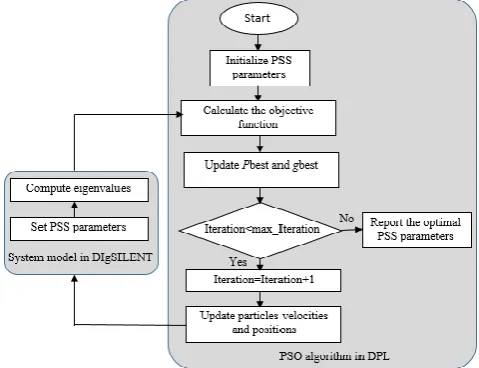
The state of each particle is represented by its position and velocity. The flowchart of the procedure is shown in Fig.3.
Copyright to IJAREEIE 10.15662/ijareeie.2015.0402004 527
In every iteration, position and velocity of each particle is updated with two following equations:
𝑣𝑖
(
𝑘 + 1)
= 𝜔 × 𝑣𝑖(
𝑘)
+ 𝑐1× 𝑟1(
𝑝𝑏𝑒𝑠𝑡𝑖− 𝑥𝑖(
𝑘))
+ 𝑐2× 𝑟2(
𝑔𝑏𝑒𝑠𝑡(𝑘) − 𝑥𝑖(
𝑘))
(8)
𝑥
𝑖(
𝑘 + 1
)
= 𝑥
𝑖(
𝑘
)
+ 𝑣
𝑖(
𝑘 + 1
)
(9)
Where: r1 and r2 are the random numbers between 0 and 1. c1 is the self confidence factor and c2 is the swarm confidence factor. w is the inertia factor that calculated with the following equation:
𝑤 = 𝑤
𝑚𝑎𝑥− (𝑤
𝑚𝑎𝑥− 𝑤
𝑚𝑖𝑛) × 𝑖𝑡𝑒𝑟𝑎𝑡𝑖𝑜𝑛 𝑖𝑡𝑒𝑟𝑎𝑡𝑖𝑜𝑛
⁄
𝑚𝑎𝑥(10)
Where 𝑤𝑚𝑎𝑥 and 𝑤𝑚𝑖𝑛 are initial and final weight respectively 𝑖𝑡𝑒𝑟𝑎𝑡𝑖𝑜𝑛𝑚𝑎𝑥 and 𝑖𝑡𝑒𝑟𝑎𝑡𝑖𝑜𝑛 are maximum and current iteration number. Furthermore in each iteration the fitness value is stored. This position is called pbest. The best position among all iteration is also stored, that is named global best. When the maximum number of iteration is reached, position of global best is returned as the optimal values that found. An important aspect of the PSO is that the ratios of the three elements that influence the particle velocity in the optimization process can be modified. Therefore, the particle performance toward the optimal solution can be enhanced controlling the weighting coefficients [7].
IV.OBJECTIVE FUNCTION
During an unstable condition, the declining rate of the power system oscillation is determined by the highest real part of the eigenvalue in the power system and the magnitude of each oscillation by its damping ratio [14].
Hence, for our optimization problem, an eigenvalue based multi-objective function reflecting the combination of real part and damping ratio is considered as follows:
𝐽 = 𝐽
1+ 𝛼𝐽
2(11)
Where:
𝐽
1=
∑
𝜎𝑖≥𝜎0(𝜎
0− 𝜎
𝑖)
2(12)
𝐽
2=
∑
𝜁𝑖≤𝜁0(𝜁
0− 𝜁
𝑖)
2(13)
Here 𝜎𝑖 and 𝜁𝑖 are the real part and damping ratio of the ith eigenvalues and 𝛼 is scaling factor.
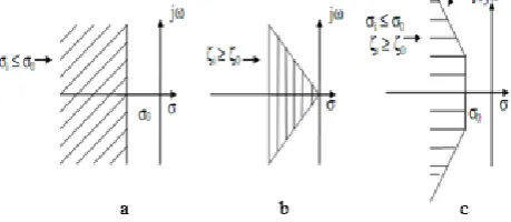
The value of 𝜎0 determines the relative stability in terms of damping factor margin provided for constraining the placement of eigenvalues during the process of optimization. The eigenvalues are placed in the region to the left of dashed line as shown in Fig. 4a, if only 𝐽1 were to be taken as the objective function.
Similarly, if only 𝐽2 is considered, then it limits the maximum overshoot of the eigenvalues as shown in Fig. 4b. In the case of 𝐽2, 𝜁0 is the desired minimum damping ratio which is to be achieved. When optimized with 𝐽 the eigenvalues are restricted within a D-shaped area as shown shaded in Fig. 4c [17].
Copyright to IJAREEIE 10.15662/ijareeie.2015.0402004 528
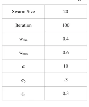
The parameters of PSO algorithm and the constants coefficient in objective function is given in table I.
Table I. Parameters used for PSO algorithm
Swarm Size 20
Iteration 100
wmin 0.4
wmax 0.6
𝛼 10
𝜎0 -3
𝜁0 0.3
Also, in this study the following constrains has been considered for all PSS:
0.01 ≤ 𝑇
𝑖≤ 3 𝑖 = 1, 2, 3, 4
(14)
1 ≤ 𝐾
𝑃𝑆𝑆≤ 50
(15)
V.FUZZY SYSTEM
In order to increase the efficiency of PSS in suppressing low-frequency oscillations and improving power systems stability, one of the important subjects is the selection of suitable installing location. It is very valuable for the system planner who needs to identify the suitable location of PSS [18].
In various studies participation factor (PF) technique was utilized to determine the possible location of PSSs before using the optimization methods in tuning the PSS parameters [14]. The second way is proposed by [19] where it uses the GA and a bits control (1: PSS installed, 0:PSS not installed) to find out the location of PSS. In [3] by using PF and GA the optimal location of PSSs are determined.
In this study, a list of all possible locations prepare and by a fuzzy system with proper membership function and fuzzy rules indexed by a decision variable (PSS location). Fig .5 shown this fuzzy approach that implemented in Matlab/fuzzy toolbox. The input of fuzzy system are the real part and damping ratio of critical eigenvalue. Here we use eight critical eigenvalue corresponding to the number of mechanical modes.
Fig. 5 Fuzzy approach used for decision variable
Copyright to IJAREEIE 10.15662/ijareeie.2015.0402004 529
Fig. 6 Membership functions for real part and damping ratio
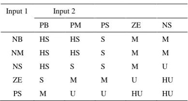
In Table II HS (High Stable), S (Stable), M (Medium), U(Unstable) and HU (High Unstable) are the membership functions of output and here these are constant numbers for the use of Takagi-Sugeno [20].
Table II. FUZZY RULES
Input 1 Input 2
PB PM PS ZE NS
NB HS HS S M M
NM HS HS S M M
NS HS S S M U
ZE S M M U HU
PS M U U HU HU
Then PSS location index for every possible state calculate using following equation:
𝑃𝑆𝑆
𝑙𝑜𝑐𝑎𝑡𝑖𝑜𝑛(𝑘) =
∑
𝑛𝑖=1𝑘
𝑖∙ 𝑜𝑢𝑡(𝑖)
(16)
Where n is total number of mechanical mode, k is a possible location for PSS and ki are the weight coefficients of each
critical eigenvalue. The larger value of this index show a better location for PSS.
In a power system with N machines and m PSS the maximum possible location for PSS obtain from following equation:
∑
𝑁𝑚=1𝐶
𝑚𝑁= 2
𝑁− 1
(17)
VI. SIMULATION RESULT
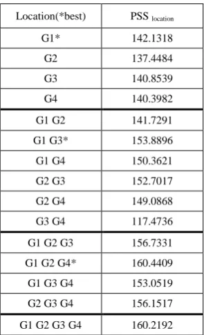
First for all possible PSS location the optimization perform and then the critical eigenvalue of system sent to the fuzzy system. As shown in Table III the best PSS locations for the case of using one generator is G1, while generators G2, G3 and generators G1, G2, G4 are the best places for PSS installation for the cases of using two and three generators.
Copyright to IJAREEIE 10.15662/ijareeie.2015.0402004 530
Table III. LOCATION INDEX FOR PSS
Location(*best) PSS location
G1* 142.1318
G2 137.4484
G3 140.8539
G4 140.3982
G1 G2 141.7291
G1 G3* 153.8896
G1 G4 150.3621
G2 G3 152.7017
G2 G4 149.0868
G3 G4 117.4736
G1 G2 G3 156.7331
G1 G2 G4* 160.4409
G1 G3 G4 153.0519
G2 G3 G4 156.1517
G1 G2 G3 G4 160.2192
In order to evaluate the performance of the proposed method some time domain simulations also have been performed in DIgSILENT and the result are brought in this section.
Table IV. OPTIMAL PSS PARAMETERS
No.
PSS G1 G2 G3 G4
𝜁
𝑚𝑖𝑛1 K T1 T2 T3 T4 33.13672 2.66415 0.83840 2.17140 0.19571
- - - 0.09238
2 K T1 T2 T3 T4 37.91608 2.428859 0.40301 2.484755 1.221033 - 30.24576 1.895991 0.217079 1.988324 0.873067
- 0.41452
3 K T1 T2 T3 T4 38.82351 1.920123 0.253218 1.337037 0.564766 18.44892 2.61452 1.098702 0.58639 0.243773 - 30.9717 1.634517 2.220365 2.957054 0.185805 0.43333 4 K T1 T2 T3 T4 25.97965 2.560139 0.68009 2.014596 0.360339 17.90244 1.18805 0.255519 0.768425 1.130924 38.1659 0.7342 1.915358 2.038576 0.771967 33.33862 1.691168 0.177361 1.021927 0.806284 0.40899
Copyright to IJAREEIE 10.15662/ijareeie.2015.0402004 531
Fig. 7 and 8 shows the speed response of generator 2 and 3 during the mentioned disturbance. As shown in this figure when using 4 PSO based tuned PSS, achieve good results and provide superior damping in comparison the conventional method. Setting for the conventional method taken from [1].
Fig. 7 Speed response of generator 2 for a three-phase 0.5s short circuit in bus 8 (for the case of using 4 PSS)
Fig. 8 Speed response of generator 3 for a three-phase 0.5s short circuit in bus 8 (for the case of using 4 PSS)
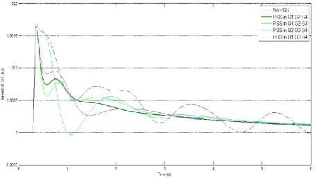
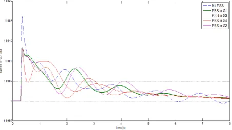
Fig. 9 illustrates speed response of generator 1, G1, when 3 tuned PSS installed in different possible locations. As expected from the fuzzy system, the best place to install PSSs for this case is when the PSSs are located in G1, G2 and G4. The same procedure is applied for the case of using 2 and 1 PSS in considered multi machine power system. Fig. 10 and 11 show speed response of G4 and G3 for the case of using 2 and 1 PSS in system. For this cases it is clear that when PSSs are placed in G1, G3 for case of 2 PSS and G1 for case of 1 PSS the maximum damped speed response has been achieved.
Copyright to IJAREEIE 10.15662/ijareeie.2015.0402004 532
Fig. 10 Speed response of generator 4 for a three-phase 0.5s short circuit in bus 8 (for the case of using 2 PSS)
Fig. 11 Speed response of generator 3 for a three-phase 0.5s short circuit in bus 8 (for the case of using 1 PSS)
VII.CONCLUSION
In this paper, a hybrid approach was applied for tuning and finding the best locations for power system stabilizer in multi machine power systems. A multi machine power system (Two Area Four Machine) that recommended for LFO stability studies, was simulated. All possible PSS locations listed and PSSs was tuned by using PSO algorithm implemented in DIgSILENT. Then by a fuzzy system which accept the real part and damping ratio of critical eigenvalue an index defined for optimal PSS place. A number of time domain simulation was perform to evaluate the performance of proposed approach. The obtained results show that the proposed method can find the optimal locations and the best PSSs parameters simultaneously with an excellent global damping performance.
REFERENCES
[1] Babaei, E., Galvani, S., and Ahmadi Jirdehi, M., “Design of robust power system stabilizer based on PSO”, IEEE Symposium on Industrial Electronics and Applications, Kuala Lumpur, pp. 325-330, Oct. 2009.
[2] Fereidouni, A. R., Vahidi, B., Hoseini Mehr, T., and Tahmasbi, M., “Improvement of low frequency oscillation damping by allocation and design of power system stabilizers in the multi-machine power system”, International Journal of Electrical Power & Energy Systems, vol. 52, pp. 207-220, 2013.
[3] Hassan, H., Moghavvemi, M., Almurib, A. F., Muttaqi, K. M., and Velappa, G., “Optimization of power system stabilizers using participation factor and genetic algorithm”, International Journal of Electrical Power & Energy Systems, vol. 55, pp. 668-679, 2014.
[4] Kashki, M., Abdel-Magid, Y. L., and Abido, M. A., “Parameter optimization of multi machine power system conventional stabilizers using CDCARLA method”, International Journal of Electrical Power & Energy Systems, vol. 32, pp. 498-506, 2010. [5] Panda, S., Yegireddy, N. K., and Mohapatra, S. K., “Hybrid BFOA–PSO approach for coordinated design of PSS and SSSC-based controller considering time delays”, International Journal of Electrical Power & Energy Systems, vol. 49, pp. 221-233, 2013.
Copyright to IJAREEIE 10.15662/ijareeie.2015.0402004 533 [7] Stativa, A., Gavrilas, M., and Stahie, V., “Optimal tuning and placement of power system stabilizer using Particle Swarm
Optimization algorithm”, International Conference and Exposition on Electrical and Power Engineering (EPE), Lasi, pp. 242-247, Oct. 2012.
[8] Ali, E. S., “Optimization of Power System Stabilizers using BAT search algorithm”, International Journal of Electrical Power & Energy Systems, vol. 61, pp. 683-690, 2014.
[9] Sheetekela, S., and Folly, K. A., “Breeder Genetic Algorithm for Power System Stabilizer design”, IEEE Congress on Evolutionary Computation (CEC), pp. 1-7, July 2010.
[10]Supriyadi, A. N., Takano, H., Murata, J., and Goda, T., “Adaptive robust PSS to enhance stabilization of interconnected power systems with high renewable energy penetration”, International Journal of Renewable Energy, vol. 63, pp. 767-774, 2014. [11]Abido, M. A., and Abdel-Magid, Y. L., “Robust design of multi machine power system stabilizers using Tabu search algorithm”,
IEE Proceedings Generation, Transmission and Distribution, vol. 147, no. 6, pp. 387-394, Nov. 2000.
[12]Zhijian, L., Hongchun, S., and Jilai, Y., “Coordination control between PSS and SVC based on improved genetic - Tabu hybrid algorithm”, 9th International Conference on Sustainable Power Generation and Supply(SUPERGEN), Nanjing, pp. 1-5, April
2009.
[13]Al-Hinai, A. S., and Al-Hinai, S. M., “Dynamic Stability Enhancement using Particle Swarm Optimization Power System Stabilizer”, 2nd International Conference on Adaptive Science & Technology (ICAST), Accra, pp. 117-119,Jan. 2009.
[14]Eslami, M., Shareef, H., Mohamed, A., and Khajehzadeh, M., “Optimal location of PSS using improved PSO with chaotic sequence”, International Conference on Electrical, Control and Computer Engineering (INECCE), Pahang, pp. 253-258, June 2011.
[15]Kundur, P., Power system stability and control. McGraw-Hill Professional; 1994.
[16]Abedinia, O., Naderi, M. S., Jalili, A., and Khamenehpour, B., “Optimal tuning of multi-machine Power System Stabilizer parameters using Genetic-Algorithm”, International Conference on Power System Technology (POWERCON), Hangzhou, pp. 1-6, Oct. 2010.
[17]Shayeghia, H., Shayanfar, H. A., Safari, A., and Aghmasheh, R., “A robust PSSs design using PSO in a multi-machine environment”, International Journal of Energy Conversion and Management, vol. 51, pp. 696-702, 2010.
[18]Qisheng, L., Zhijuan, Y., Xiaobo, H., and Hong, L., “Study on the selection of PSS installing locations in power systems”, 2005 IEEE/PES Transmission and Distribution Conference and Exhibition, Dalian, pp. 1-4, 2005.
[19]Hongesombut, K., Mitani, Y., and Tsuji, K., “Power system stabilizer tuning based on multi objective design using hierarchical and parallel micro genetic algorithm”, International Conference on Power System Technology, vol. 1, pp. 402-407, Nov. 2004. [20]Keumarsi, V., Simab, M., and Shahgholian, Gh., “An integrated approach for optimal placement and tuning of power”,
International Journal of Electrical Power and Energy Systems, Vol. 63, pp. 132-139, 2014.
BIOGRAPHY
Ebrahim Saadati was born in Isfahan, Iran, in 1991. Hegraduated from Ilam University, Iran, with B.E. degree in electrical power engineering in 2013. He is currently working toward his Master degree at Yazd University, Iran. He is familiar with specialized software, including Matlab/Simulink and DIgSILENT. His current research interests include power electronics, flexible ac transmission systems and power system stability.
Aliakbar Damaki
was born in Yazd, Iran, in 1983. He received the Ph.D. degree in electricalengineering from the Amirkabir University of Technology, Iran, in 2012. Since 2012, he has been with the Dept. of ECE, Yazd, where he was an Assistant Professor. His main research interests: Design, Analysis, and Prototyping of Electrical Machinery, Analytic and Finite Element Modelling of Electrical Machinery, Power System Dynamic and Stability, Flexible AC Transmission Systems.
Saman Radman was born in Ramsar, Iran, in 1989. He graduated from Islamic Azad University of