Design and Implementation of U-Slot Patch
Antenna for WLAN Applications
A.Dinesh Kumar
1, R.Saranya
2Embedded Trainer, Raysofit Solutions, Chennai, Tamilnadu, India 1
Assistant Professor, Dept. of ECE, Agni College of Technology, Chennai, Tamilnadu, India 2
ABSTRACT: In this paper, the design and implementation of a co-axial feed U-slot microstrip antenna for 5.5 GHz WLAN application is presented. The VSWR (Voltage Standing Wave Ratio) and the return loss of this proposed structure are studied and analyzed using Computer Simulation Technology (CST) microwave studio, it’s based on the method of finite difference time domain techniques to achieve the desired specification. The proposed antenna based on co-axial feed configuration has the maximum achievable bandwidth obtained about 260 MHz (5.36-5.62 GHz) at -10db reflection coefficient which corresponds to WLAN 5.5 GHz frequency band and maximum achievable gain is 5.3db at 5.5 GHz centre frequency. The stable VSWR and low return loss are obtained across the frequency band compared to the existing system.
KEYWORDS: U-Slot Microstrip Antenna, Wide Band, WLAN, Return Loss, VSWR.
I.INTRODUCTION
The growth of wireless systems and booming demand for a variety of new wireless applications such as WLAN (Wireless Local Area Network), it is important to design broadband and high gain antennas to cover a wide frequency range. The design of an efficient wide band small size antenna, for recent wireless applications, is a major challenge. In applications like high performance aircraft, satellite, missile, mobile radio and wireless communications small size, low-cost fabrication, low profile, conformability and ease of installation and integration with feed networks are the main constraints. Also, with advancement of the technology, the requirement of an antenna to resonate at more than one frequency i.e. multi-banding is also increasing day by day. Here microstrip patch antenna is the best choice to fulfill all the above requirements. Along with that a microstrip patch antenna offers many advantages above other conventional antennas like low fabrication cost, supports both, linear as well as circular polarization etc. Microstrip patch antenna have some disadvantages also like surface wave excitation, narrow bandwidth etc. But bandwidth of a microstrip patch antenna can be improved by various methods like cutting U-slot, increasing the substrate height, decreasing 𝜀𝑟 of substrate etc. Antenna array can also be used to improve the bandwidth .
Here, to start with, a proposed antenna with coaxial feed is designed. In this feeding technique, the inner conductor of the coaxial connector extends from ground through the substrate and is soldered to the radiating patch, while the outer conductor extends from ground up to substrate. The main advantage of this type of feeding scheme is that the feed can be placed at any desired location inside the patch in order to properly match with its input impedance. This feed method is easy to fabricate and has low spurious radiation. Recently many microstrip patch antenna for different applications with coaxial-feed have been presented [5-8]. Figure 1 shows the co-axial feeding technique. Further, the details of the proposed design performance are presented and discussed.
II.ANTENNA DESIGN
The proposed antenna geometry is shown in figure 2 and 3, where a coaxial-fed rectangular patch is printed over a fr4 substrate of thickness h=1.6 mm and permittivity 𝜀𝑟 =4.3. A U-slot is cut on the patch surface, which is mounted over the substrate of size Lg x Wg = 22.20 x 26.38 mm. the other side of the substrate is coated with metal, which is the
ground plane of the antenna.
Fig .2 Geometry of U-Slot Microstrip Antenna: Top View
The feed point for the proposed antenna is found to be (0, 6.30) where the best impedance matching of 50ohm. This has been done by applying parametric sweep for locating the feed point in the full range of y-axis in the window of the transient solver. Proper impedance matching always yields the best desired result.
Fig .3 Simulated Design Structure
The dimensions of the antenna that give a broad bandwidth are listed in Table I, which are obtained via iterative process.
TABLE I
DIMENSIONS OF PROPOSED U-SLOT MICROSTRIP ANTENNA
Parameter L W LS WS a b Yf
III. SIMULATION AND IMPLEMENTATION RESULTS
Simulation studies of proposed antenna reported here are carried out using CST Microwave studio. Figure 4 shows the simulated reflection coefficient [S11] of the proposed antenna in db. S11 gives the reflection coefficient at port 1 where
we apply the input to the microstrip antenna. It should be less than -10 db for the acceptable operation. It shows that the proposed antenna resonates at frequency equal to 5.5 GHz which gives the measure of the wideband characteristic of the microstrip antenna. The simulated impedance bandwidth of about 260 MHz (5.36-5.62 GHz) is achieved at -10 db reflection coefficient. The reflection coefficient value that is achieved at this resonant frequency is equal to -16.16 db. This reflection coefficient value suggests that there is good matching at the frequency point below the -10 db region. It covers the frequency band for the WLAN application i.e. 5.36-5.62 GHz.
Fig 4. Simulated Reflection Coefficient [S11] of U-slot Microstrip Antenna
Figure 5 shows the VSWR (Voltage Standing Wave Ratio) plot for the designed antenna. The value of VSWR should lie between 1 and 2. SWR is used as an efficiency measure for transmission lines, electrical cables that conduct radio frequency signals, used for purposes such as connecting radio transmitters and receivers with their antennas, and distributing cable television signals. Here the value of the VSWR for the proposed U-slot microstrip antenna is 1.36 at the specified resonating frequency bands for 5.5 GHz WLAN application
Fig 5.Simulated VSWR of U-slot Microstrip Antenna
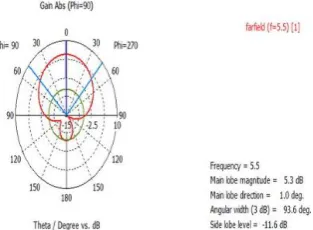
Figure 6 shows the maximum achievable gain is 5.3 db at the resonating frequency of 5.5 GHz. In this proposed design a gain of 5.3 db has been investigated for the frequency of 5.5 GHz. The value of gain is not good enough for an acceptable operation. We can further analyse this designed structure by cutting different slots on the microstrip.
Figure 7.Fabrication of U-Slot Patch Antenna
Implementation of U-slot patch antenna on FR4 substrate with co-axial feeding and compact size.
Figure 8.Tested on Network Analyser
Fabricated antenna connected to vector network analyser through SMA connector.
Fabricated antenna result for return loss with desired frequency.
Figure 10.Tested Result VSWR
Fabricated antenna result for VSWR with desired frequency.
IV.DISCUSSION
In this study, a simple coaxial fed u-slot microstrip antenna for application in 5.5 GHz WLAN frequency band has been demonstrated and implemented using CST Microwave studio software. The proposed antenna is designed to operate at 5.5 GHz WLAN frequency band which corresponds to IEEE 802.11 (5.18-5.8 GHz) WLAN application. It can be observed that the achievable impedance bandwidth of 260 MHz at the resonating frequency of 5.5 GHz is obtained due to proper impedance matching at the optimized feed point on the design. The reflection coefficient and VSWR achieved at the resonant frequency is equal to -16.16 db and 1.36. Hence it covers the WLAN band (5.18-5.8) GHz
V. CONCLUSION
In this study, a U-slot coaxial fed microstrip antenna for application in 5.5 GHz WLAN frequency band has been demonstrated and implemented using CST Microwave Studio Software. The proposed antenna exhibits a bandwidth of about 260 MHZ (5.36-5.2 GHz) at -10 db reflection coefficient which corresponds to 5.5 GHz WLAN standard. The maximum achievable gain is 5.3 db with the corresponding reflection coefficient of the -16.16 db. The proper impedance matching of the proposed antenna is achieved by adjusting the coaxial feeding structure. In addition, the proposed antenna shows stable VSWR and return loss over the band which makes the design suitable for wireless communication applications, the design concept can be extended to other frequency bands of interest by cutting various slots shapes on the patch or in the ground, thus making the ground a defected ground structure.
REFERENCES
[1] M. Mahmoud, “Improving the Bandwidth of U-slot Microstrip Antenna Using a New Technique (Trough-Slot Patch)” Region 5 IEEE Conference. Vol. 2, N0. 3, pp. 43-47,2011.
[2] R. Garg, P. Bhartia, I. Bahl and A.I tipiboon, “Microstrip antenna design handbook”, Artech House, Boston – London, 2000. [3] C. A. Balanis, “Antenna Theory Analysis and Design”, Third Edition, Wiley, New Jersey, 2005.
[4] N.A. Murad, M. Esa and S. Tukachil, “Microstrip U-Shaped Dual-Band Antenna” Asia-Pacific conference on Applied Electromagnetics Proceedings,Vol.1, No. 4, pp.56-59, 2005.