ANN Based MPPT Controller for Standalone Solar
PV-Battery System with Three-Level Boost Converter
Damodhar Reddy
1, K Suresh
2, T Srinivasulu
3, CH Suresh
4Department of EEE 1,2,3,4, Hyderabad Institute of Technology and Management1,2,3,4
Email: [email protected]1, [email protected], [email protected]3, [email protected]4
Abstract- In this paper, a radial basis function network (RBFN) controller based three-level boost converter is presented for DC/DC conversion in the solar PV (Photovoltaic) –Battery hybrid system. A neural network based RBFN controller is involved in converter control and maximum power point tracking (MPPT) to trace the maximum power point. The three-level boost converters have a wide range of application in power conversion systems with continuous supply current and high voltage gain. Three-level converter configuration can minimize the voltage stress across the switches and also have a capability of maximum energy transfer from input to output through the series connected boost inductors. In this paper, RBFN MPPT controller based three-level boost converter is designed for 1.2kW solar PV system with input voltage range of 0-110V and output DC voltage of 400V and the results are carried out in MATLAB-Simulink.
Keywords-Solar PV System, MPPT, Artificial nueral network (ANN), three-level boost converter, Battery.
1. INTRODUCTION
Electricity demand is increasing from the past decades due to excessive utilization of power in various sectors. It becomes very expensive to end users as per economic point view due to high production cost with conventional energy resources such as fossil fuels. In order to overcome the difficulties in power generation to meet the load demand, the government policies and industrial sectors are forced to concentrate towards green energy solutions called Renewable Energy Resources [1, 2]. The renewable energy resources are playing a vital in the power sector due to abundant energy availability in nature such as solar, wind, fuel cell, tidal, thermal and ocean etc. Apart from all, the solar and wind energy conversion systems are the dominant energy resources for eco-friendly energy conversion. Due to immense advancement in low cost and highly efficient power converters, the conversion of renewable energy becomes simple. The installation of solar PV systems [3-4] is quite easy than other form of energy structures. There are many MPPT control techniques [5-6] proposed by the researchers to extract the maximum power from the renewable energy systems such as incremental conductance (INC), Perturbation & Observation (P & O), hill climb method, fuzzy logic [7, 8] and artificial intelligence based controllers etc. The perturbation & observation and hill climb methods are regularly used MPPT techniques [9-11] in solar and wind energy conversion systems due to simple structures but limited by low power tracking capability and also have low accuracy. This kind of MPPT controllers is essential for solar, wind and fuel cell energy system to trace the maximum power point and also control the DC to DC converters. However, the convergence of the aforementioned MPPT techniques is low and not suitable for non linear systems. Here the PBFN MPPT controller [12] can defeat the drawbacks of conventional MPPT techniques even for non linear systems with fast convergence.
The two-level DC to DC boost converters [13-15] plays a significant role in the renewable integration of solar PV and fuel cell energy systems to enhance the voltage level. Due to low efficiency, low power density and high voltage stress across the switches, this kind of converters are replaced by the three-level boost converters [16] which offers high power density and reduced switching losses. The three-level boost converters are widely used in the solar PV systems for DC/DC conversion with low voltage stress across the switches, low ripple content and high efficiency [17]. In this paper, RBFN MPPT controller based three-level boost converter configuration is designed for solar PV system with battery bach-up. The Preferred converter configuration is designed for variable solar irradiations at constant temperature.
2. DESIGN OF STANDALONE SOLAR PV SYSTEM WITH BATTERY
The block diagram of proposed model configuration is depicted in Fig.1. In this system, it consists of a PV panel, MPPT controller, three level converter and battery. Here, the PV voltage (VPV) and current (IPV) are
Fig.1 Block diagram of a standalone solar PV system
2.1. Solar PV Cell
A simple and accurate solar PV cell is designed with a single diode of p-n junction semiconductor device to absorb a temperature and irradiance of solar energy with non-linear characteristics and converted into DC current. The cell is coupled in series and/or parallel in order to get the level of voltage/current depending on the requirement. Solar cells are connected in series for voltage and are connected in parallel for current. The equivalent circuit diagram of solar PV cell with diode, series and parallel resistances is displayed in Fig.2. The solar PV cell design specifications of current are derived from the equations-1, 2 and 3. Similarly, the design specifications of PV array are also tabulated in Table 1.
p s
a s
s s
pv
R
IR
V
kT
N
IR
v
q
I
I
I
(exp[
(
)
1
])
(
)
(1)n pv
n pv
G
G
T
K
I
I
(
,
1
)
(2)]
1
)
(
exp[
)
(
, 1
q
T
k
N
T
K
v
TI
K
I
I
a s
v oc
n sc
s (3)
Fig.2 Ideal circuit diagram of the solar PV cell
Where, Ipv = solar PV current, In,pv = solar PV nominal
current, q= Electron charge (1.602x10⁻¹⁹c), k=Boltzmann constant(1.38065x10⁻²³J/K), Is= saturation
current, a= Diode ideality constant, K1= Ratio of short
circuit current variation with temperature, Isc = short
circuit current, Voc = open circuit voltage, Ns= number of
arrays connected in series, Kv= Ratio of open circuit
voltage variation with temperature, T=Absolute
temperature, Tn= Nominal temperature, ∆T= Deviation
in temperature, G= Irradiance and Gn= Nominal
irradiance. In this presented system, the SUNPOWER SPR-305-WHT-type array is chosen for solar PV system design with 2-series modules and 2-parallel strings as shown in the Fig.3.
Fig.3 P-V and I-V characteristics of the solar PV array
Table.1: PV array specifications (SUNPOWER-305-WHT)
S.No Array specifications Ratings
1 Open circuit voltage (Voc) 64.2V
2 Short circuit current (Isc) 5.96A
3 Maximum power point
voltage (Vmp)
54.7V
4 Maximum power point current
(Imp)
5.58A
5 Series Resistance (Rs) 0.03789Ω
6 Parallel Resistance (Rp) 993.5 Ω
7 Diode saturation current (Isat) 1.17e-8A
8 Diode quality factor (Qd) 1.3
2.2.Three Level Converter
The three-level boost converters [16] are displayed in Fig.4, which employs for DC to DC conversion with the enhanced voltage level at the DC-link. It consists of two input capacitors (Cp1 and Cp2), two input inductors
(Lp1 and Lp2), two primary diodes (Dp1 and Dp2), DC-link
capacitors (Co1 and Co2) and load (R=R1+R2). For the
boost operation of the converter, both switches operated at same duty cycle with 1800 phase shift.
Id IPV
RS
RP
I
V
0 20 40 60 80 100 120 140
0 5 10
1 kW/m2
C
u
rr
e
n
t
(A
)
Voltage (V)
Array type: SunPower SPR-305-WHT; 2 series modules; 2 parallel strings
0.75 kW/m2 0.5 kW/m2 0.25 kW/m2
0 20 40 60 80 100 120 140
0 500 1000
1 kW/m2
P
o
w
e
r
(W
)
Voltage (V)
Fig.4 Circuit diagram of three-level DC/DC Boost converter [16]
The converter is operated at a duty cycle above and below 0.5. The circuit operation (Fig.4) is elaborated in four modes by operating switches with proper switching pattern as depicted in Fig.5 for duty cycle D<0.5 and Fig.6 for duty cycle D>0.5. The design specifications considered for the circuit are tabulated in Table.2 for a maximum of 1000W/m2 irradiation.
Mode.1 (t0-t1): When S1 is in ON state and S2 is in OFF
state, the input inductor Lp1 start charging from input
through the switch at the rate of
) ( 2 )
( 0 0
1
1 t t
L V t i i
i PV Lp
Lp and the inductor Lp2
discharges at the rate of
) ( 2 )
( 0 0
2
2 t t
L V t i i
i PV Lp
Lp . Similarly, the output
capacitor Co2 discharges through the load R2, where
diode Dp1 is inactive and Dp2 active.
Mode.2 (t1-t2): When S1 and S2 are in OFF state, the
input inductor Lp1 and Lp2 releases the energy through
the output capacitors Co1 and Co2 respectively. The
inductors currents iL1 and iL2 dropped to minimum, at
which duty cycle is below 0.5 (D<0.5).
Mode.3 (t2-t3): When S2 is in ON state and S1 is in
OFF state, the input inductor Lp2 start charging
from input through the switch at the rate of
) ( 2 )
( 0 0
2
2 t t
L V t i i
i in Lp
Lp and the inductor Lp1
discharges at the rate of ( )
2 )
( 0 0
1
1 t t
L V t i i
i in Lp
Lp
. Similarly, the output capacitor Co1 discharges through
the load R1, where diode Dp1 is active and Dp2 inactive.
Fig.5 Three-level DC/DC boost converter waveforms for D < 0.5 [16]
Mode.4 (t3-t4): When S1 and S2 are in ON state, the
input inductor Lp1 and Lp2 charges the energy at the rate
of
i in
L V
2 . The inductors currents iL1 and iL2 reached to
maximum, at which duty cycle is above 0.5 (D>0.5). Table.2: Circuit specifications for 1000 W/m2
S.No Circuit specifications Ratings
1 Input voltage (Vin) from PV 0-110V
2 Maximum output voltage (Vdc) 400V
3 Maximum output current (Idc) 3.03A
4 Maximum output power (Pdc) 1.2kW
5 Input capacitance (C=Cp1=Cp2) 6.6μF
6 Input inductance (LP1= LP2) 0.25mH
7 Output capacitance (Co1+Co2) 470μF
8 Load resistance (R1+R2) 133.3Ω
9 Switching frequency (fsw) 20kHz
Vdc1
S1
Co1
Vdc2 Co2 Dp1
Dp2 Cp1
Cp2
Lp2 S2
R1
R2 Lp1
PV
Vs1
Vs2
iLp1
iLp2
t t
t
t
Ts Ts Ts
1 2 3 2 1 2 3 2 1
t0 t1 t2 t3 t4
Vg1
Vg2
t
t
ON OFF ON OFF ON OFF
OFF
ON ON OFF ON OFF
Vs1
Vs2
iLp1
iLp2
t t
t
t
Ts Ts Ts
1 4 3 4 1 4 3 4 1
t0 t1 t2 t3 t4
Vg1
Vg2
t
t
ON OFF ON OFF ON
OFF
OFF
Fig.6 Three-level DC/DC boost converter waveforms for D > 0.5
For the above circuit diagram (Fig.4), the duty cycle (D) can be written as,
o in o
V
V
V
D
(4)Where Vo= DC output voltage, Vin = VPV = Input
voltage, VfD = Diode forward voltage and Ts =
Switching time. The voltage across input capacitors is half of the input voltage from solar PV array.
2
2
1 Cp in
Cp
V
V
V
(5)The input inductances can be written as,
)
.
(
2
(min) max 2 1 s L in p pf
i
D
V
L
L
(6)Where Dmax =Maximum duty cycle, ΔiL = inductor
ripple current, and fs=switching frequency. And ΔiL can
be written as,
inL
i
i
10
%.
, where ɳ= Efficiency (7)The output capacitance Co1 and Co2 can be written as,
)
.
(
2
.
(min) max 2 1 s Co o o of
V
D
i
C
C
(8)Where ΔVC = Capacitor ripple voltage, io = DC load
current and DC-link capacitance = Co= Co1 +Co2
)
1
(
%.
10
D
V
V
Co in
(9)The input capacitance Cp1 and Cp2 can be written as,
)
.
(
2
.
(min) max 2 1 s Cp Li p pf
V
D
i
C
C
(10)Where ΔVCp = Series capacitor ripple voltage and iLi
= Input current. The voltage across output capacitors Co1
and Co2 is half of the output voltage at DC-link.
2
2
1 Co dc
Co
V
V
V
(11)3. ANN BASED MPPT CONTROLLER
In the present scenario, artificial intelligent MPPT techniques are more popular over the conventional control techniques due to the fast and dynamic response of the system with non-linear system control capability. Artificial Neural network based RBFN controller is easy to implement with very less computational input data even for wide variations in input. The maximum power point tracking of SPVS can be obtained by considering the PV output parameters (voltage and current) as an input variable to the RBFN controller. The input data is trained in such way that the converter is controlled to get the desired output voltage, where the output of the controller is a duty cycle.
It has both supervised and unsupervised phases with three layer network called input layer, a hidden layer, and an output layer. The hidden layer activation functions are estimated by the distance between input vector and prototype vector. In the first step, the parameters which direct the basis function are estimated by unsupervised methods and in the second step, the final layer units are decided. The input variables (xi1) to
an RBFN controller are voltage and current, and the output variable (yk3) is a duty cycle (D). The controller
output as depicted in Fig.7 is given to the PWM (Pulse Width Modulation) pulse generator which generates the switching pattern for the converter and the parameters taken for an RBFN configuration are shown in Table.3.
a) Input layer:
In this layer, the measured input variables are directly transmitted to next level through the nodes. The net input and output is represented as,
) ( 1 1 N x
neti i (12)
)
(
))
(
(
)
(
1 1 11
N
net
N
net
f
N
y
i
i i
i ,Where, i=1, 2...n (13)
b) Hidden layer:
In this, a Gaussian function is performed for each and every node i.e. an RBFN is used as a membership function. The net input and output for the hidden layer is represented as,
(14)
yj2(N) fi2(netj2(N))Exp(netj2(N)),
j=1, 2…..9 (15)
Where Mean, Mj [m1jm2j...mij]Tand
Standard deviation,
j T ij j jdiag[ 1 1 ... 1 ]
2 2
2 2
1
c) Output layer:
The overall output can be computed by the summation of all the inputs through the single node k, which is represented as ∑, therefore
2( )
3
N y W
netk j j (16)
D
N
net
N
net
f
N
y
k3(
)
k3(
k3(
))
k3(
)
(17) In this controller configuration, the desired system operation is obtained by considering the minimum of 530 input data of voltage and current from PV and the response of the RBFN controller has tuned automatically according to the change in the input parameters.
j j T j 2j (N) (X M ) (X M )
Fig.7 Control model of an RBFN
4. RESULT DISCUSSION
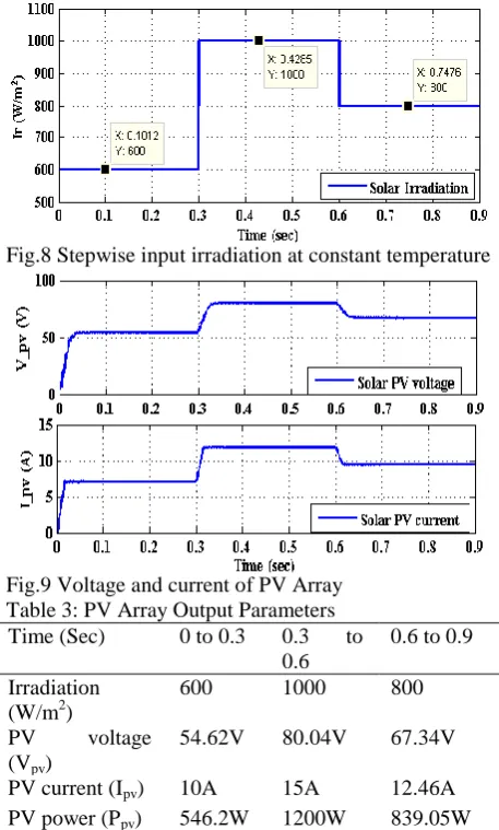
In this system, an RBFN MPPT controller based 1.2kW three level converter topology is designed for solar PV system for variable irradiations. The output of the system is analyzed at variable irradiations of 600 W/m2, 1000 W/m2 and 800 W/m2 in the time interval of 0 to 0.9 sec. The input irradiation is considered as stepwise as shown in Fig.8 and the output of the PV array (voltage and current) is obtained for corresponding irradiations at different time intervals as depicted in Fig.9 and the PV output parameters are tabulated in Table.3.
[image:5.595.310.526.157.272.2]Fig.8 Stepwise input irradiation at constant temperature
[image:5.595.61.290.313.693.2]Fig.9 Voltage and current of PV Array Table 3: PV Array Output Parameters
Time (Sec) 0 to 0.3 0.3 to
0.6
0.6 to 0.9
Irradiation (W/m2)
600 1000 800
PV voltage
(Vpv)
54.62V 80.04V 67.34V
PV current (Ipv) 10A 15A 12.46A
PV power (Ppv) 546.2W 1200W 839.05W
The output DC voltage of three-level converter is depicted in Fig.10 for various irradiations. The maximum DC output voltage of the converter is 386.3V at 1000 W/m2. The required DC voltage of 400V is
maintained with battery back-up for all the irradiations and the converter output parameters are tabulated in Table.4. The equal distribution of voltage across the output capacitors of 200V each capacitor of three-level converter is obtained in the system as depicted in Fig.11, which results in the balanced system configuration for stable operation.
Fig. 10 DC Output voltage of three-level converter
Table 4: Converter Output Parameters without Battery bach-up
Time (Sec) 0 to 0.3 0.3 to 0.6 0.6to 0.9 Irradiation
(W/m2)
600 1000 800
Voltage (Vdc) 263V 386.7V 325V
Current (Idc) 1.66A 2.217A 2.75A
Power (Pdc) 519.3W 1122W 792.3W
Fig.11 DC-link voltage of three-level converter across each of the capacitor
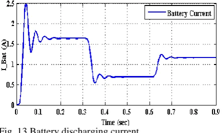
The state of charge and discharge current of the battery are shown in Fig.12 and Fig.13 respectively which will support the system to maintain rated values for all the irradiation.
[image:5.595.305.536.313.533.2] [image:5.595.313.530.625.745.2]Fig. 13 Battery discharging current
[image:6.595.66.288.322.461.2]The power output parameters of the proposed system configuration are carried out for RBFN based controller for solar PV without and with battery system. The maximum power output of converter is 1122W at 1000 W/m2 and the required power of the load is maintained at 1.2kW for all the irradiations as depicted in Fig.14.
Fig.14 Converter output power
[image:6.595.66.285.559.695.2]The variation in the current of PV, battery and load for the corresponding input irradiation is shown in the Fig.15 and the related output parameters are tabulated in Table.5. It infers that the load current is maintained at rated value with support of battery stored energy and solar PV system.
Fig. 15 Input, Output and battery current of the proposed system
Table 5: Input, output and battery current
Time (Sec) 0 to 0.3 0.3 to 0.6 0.6to 0.9
Irradiation 600 1000 800 (W/m2)
PV current
(Ipv)
10A 15V 12.46A
Battery Current (Ibat)
1.64A 0.69A 1.16A
Load current (Io)
3A 3A 3A
5. CONCLUSION
The design of 1.2kW three-level converter is carried out for a solar PV system with batteryback-up. The control analysis is carried out through MATLAB-Simulink for variable irradiation conditions. The proposed RBFN based control algorithm has shown the better results with fast convergence. The maximum efficiency of 91.9% is achieved for the proposed system configuration at 1000W/m2 irradiation and full load. This kind of converter topology is widely used in DC/DC conversion to step up the voltage to the required level based on the application. The boost type converter is essential in low power generating systems such as solar PV systems, fuel cells, switched mode power supply and other DC supplied systems. The suggested three-level converter configuration is an adequate system for solar PV systems.
REFERENCES
[1] Joshi KA, Pindoriya NM. Impact investigation of rooftop Solar PV system: A case study in India. In2012 3rd IEEE PES Innovative Smart Grid Technologies Europe (ISGT Europe) 2012 Oct 14 (pp. 1-8). IEEE.
[2] Xiao W, Edwin FF, Spagnuolo G, Jatskevich J. Efficient approaches for modeling and simulating photovoltaic power systems. IEEE Journal of Photovoltaics. 2013 Jan;3(1):500-8.
[3] Jain C, Singh B. A 3-Phase Grid Tied SPV System With Adaptive DC Link Voltage for CPI Voltage Variations. IEEE Transactions on Sustainable Energy. 2016 Jan;7(1):337-44.
[4] Kasa S, Ramasamy S. Photovoltaic fed Dynamic Voltage Restorer with Voltage Disturbance Mitigation Capability Using ANFIS Controller. International Journal of Renewable Energy Research. 2016 Jan 1;6(3):825-32.
[5] Saravanan S, Babu NR. RBFN based MPPT algorithm for PV system with high step up converter. Energy Conversion and Management. 2016 Aug 15;122:239-51.
[6] Messalti S, Harrag A, Loukriz A. A new variable step size neural networks MPPT controller: Review,
simulation and hardware implementation.
Renewable and Sustainable Energy Reviews. 2017 Feb 28;68:221-33.
[7] El Khateb A, Rahim NA, Selvaraj J, Uddin MN. Fuzzy-logic-controller-based SEPIC converter for maximum power point tracking. IEEE Transactions on Industry Applications. 2014 Jul;50(4):2349-58. [8] D. Reddy and S. Ramasamy, "A fuzzy logic MPPT
system with improved CPI voltage," 2017 Innovations in Power and Advanced Computing Technologies (i-PACT), Vellore, 2017, pp. 1-6. [9] Reddy D, Ramasamy S. Design of RBFN Controller
Based Boost Type Vienna Rectifier for Grid- Tied Wind Energy Conversion System. IEEE Access. 2018;6:3167-75.
[10] RAMASAMY S, Reddy D. Design of a Three-phase Boost Type Vienna Rectifier for 1kW Wind Energy Conversion System. International Journal of Renewable Energy Research (IJRER). 2017 Dec 30;7(4):1909-18.
[11] Singh B, Shahani DT, Verma AK. Neural network controlled grid interfaced solar photovoltaic power generation. IET Power Electronics. 2014 Mar;7(3):614-26.
[12] RAMASAMY S, Sudheer K. Mitigating Voltage Imperfections with Photovoltaic fed ANFIS based ZSI-DVR in Three Phase System. International Journal of Renewable Energy Research (IJRER). 2017 Dec 30;7(4):2103-10.
[13] Gules R, Dos Santos WM, Dos Reis FA, Romaneli EF, Badin AA. A modified SEPIC converter with high static gain for renewable applications. IEEE transactions on power electronics. 2014 Nov;29(11):5860-71.
[14] Chen YM, Huang AQ, Yu X. A high step-up 3-port dc–dc converter for stand-alone PV/battery power systems. IEEE Transactions on Power Electronics. 2013 Nov;28(11):5049-62.
[15] Debnath D, Chatterjee K. Two-stage solar photovoltaic-based stand-alone scheme having battery as energy storage element for rural deployment. IEEE Transactions on Industrial Electronics. 2015 Jul;62(7):4148-57.
[16] Kim JS, Kwon JM, Kwon BH. High-Efficiency Two-Stage three-level Grid-Connected Photovoltaic Inverter. IEEE Transactions on Industrial Electronics. 2018 Mar;65(3):2368-77.