Research Development Cell, Government College of Engineering, Jalagon (M. S), India
RF MEMS for Reconfigurable Antenna
using GSO Algorithm with ANN
Qazi Fasihuddin.Z1, Dr.M.S.S.Rukmini2
PhD Scholar, Department of ECE Engineering, VFSTR University, Guntur, India1
Professor, Department of ECE Engineering, VFSTR University, Guntur, India2
ABSTRACT: This paper presenting the study of RF-MEMS technology which is continuously growing and MEMS for reconfigurable antenna it is very interesting and most valuable issues for optimization designing. It is investigated relationship between different designing parameters and the device performance for designing a MEMS device. The structure of antenna is determined by selecting the optimal dimensions for example beam length and beam width of the antenna, Torsion arm length, Switch thickness, Holes and Gap are used. To optimize the dimensions, GSO algorithm is proposed with artificial neural network that will reduce the errors and produce optimal output at the end. The implementation of the proposed method will be done by Matlab 2013b and the performance will be analyzed with existing methodologies.
KEYWORDS: RF MEMS Reconfigurable antenna GSO Matlab.
I. INTRODUCTION
Neural networks play a vital role in the applications of wireless communications [5]. The very first preferred shape for antenna design purposes was the Sierpinski gasket, which later on converted into a reconfigurable antenna (RA) by introducing radio frequency micro electromechanical system (RF MEMS) switches [3].
There are various shapes of RF-MEMS switch like, H-shape, S-shape, spiral, log-periodic to achieve different wireless and aerospace applications. The feed-forward back-propagation (FFBP) algorithm of artificial neural network is used to optimize the switch. The optimized results of RF switch depends upon the physical parameters, dielectric as well material of substrate and beam [1].
Paras Chawlaet al [3] have proposed a mathematical neural approach/artificial neural network (ANN) for the design of a swastika-shaped reconfigurable antenna as a feed forward side. Planar antenna up to the second iteration was simulated using finite element method-based HFSS software. The developed ANN algorithm was used for optimizing the antenna to be carried out by exchanging repetitive simulations, which provide reduced processing times. Paras Chawla et al [4,5] have proposed the designing and analysis of reconfigurable antenna devices. The pull-in voltages lies between 1.912 to 2.125V at 8GHZ and voltages lies between 22.812 to 23.125Vat 10GHZ. The switching speed of microsecond were measured which is well suited for reconfigurable micro strip antenna. For the RF-MEMS switch a feed-forward back-propagation (FFBP) algorithm was used for getting the changes in some parameters The reconfigurable antenna was used to do the changes in real time in the relevant circuital characteristics and radiation properties. the reconfigurable antenna which are having different multiband are used in radar and wireless applications[6].
II. OBJECTIVE AND SCOPE OF THE STUDY
There are number of strategies that are being proposed by different researchers, scientists and several optimization techniques is used to optimize the design parameters. Hence in this work we are going to propose the following: i. To design efficient MEMS for reconfigurable antenna identify the optimal parameters.
Research Development Cell, Government College of Engineering, Jalagon (M. S), India
Copyright to IJIRSET www.ijirset.com 273
III.PROPOSEDAPPROACH
The basic aim of this research is to find out the optimal parameters for designing of efficient MEMS for reconfigurable antenna. To optimize the dimensions, GSO algorithm is proposed with artificial neural network that will reduce the errors and produce optimal output at the end.
IV. NEURAL NETWORKS ARCHITETURE
1. Feed-Forward Networks: In Feed-forward ANNs the signals are travel only in one way from input to output. There is no feedback (loops) i.e. the output of any layer does not affect that same layer.
2. Feedback Networks: With the help of loops in the network the signals can travel in both the directions in the feedback network. Feedback networks are very strong complicated. Feedback network has the dynamic behavior.
Fig 1 Feed-forward network model
Figure 1 shows the feed forward ANN which is called as Multilayer Perceptron Neural Network (MLPNN). In the MLPNN model each neuron in the input layer is acting as a buffer for distributing the input signals xi to neurons in the hidden layer. Each neuron j in the hidden layer sums up its input signals xi after weighting them with the strengths of the respective connections wij from the input layer and compute its output Yj as a function of the summation
and where f can be a simple threshold function. Parameters of the model are allowed to change[2].
V. EXPECTED PERFORMANC ANALYSIS
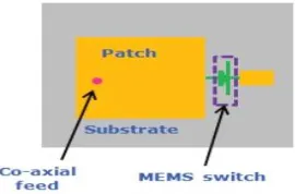
The design parameters such as beam length, beam width, length of Torsion arm, thickness of switch, Holes and Gap are used and the above data’s have to be collected for analyzing the system and evaluation purpose.
Research Development Cell, Government College of Engineering, Jalagon (M. S), India
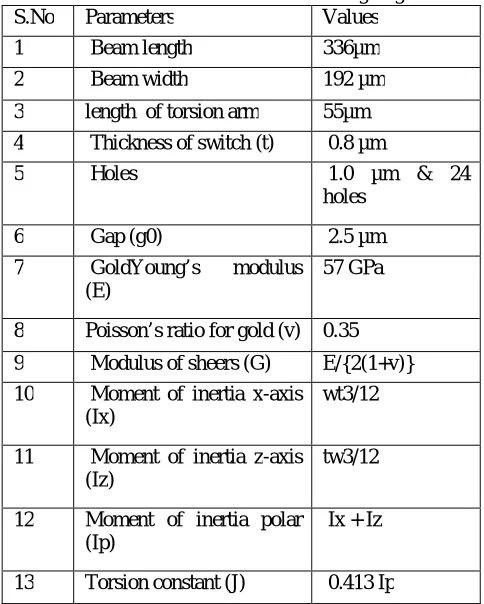
In the above figure2 substrate is of silicon material and for designing the switch different physical dimensions and material constant are used shown in the following table number 1.
Table I Parameters for switch designing S.No Parameters Values
1 Beam length 336µm
2 Beam width 192 µm
3 length of torsion arm 55µm 4 Thickness of switch (t) 0.8 µm
5 Holes 1.0 µm & 24 holes
6 Gap (g0) 2.5 µm
7 GoldYoung’s modulus (E)
57 GPa
8 Poisson’s ratio for gold (v) 0.35
9 Modulus of sheers (G) E/{2(1+v)} 10 Moment of inertia x-axis
(Ix)
wt3/12
11 Moment of inertia z-axis (Iz)
tw3/12
12 Moment of inertia polar (Ip)
Ix + Iz
13 Torsion constant (J) 0.413 Ip
Research Development Cell, Government College of Engineering, Jalagon (M. S), India
Copyright to IJIRSET www.ijirset.com 275
The Figure 3 shows the expected simulation result of the switch. In the up state position the insertion loss of -0.035dB at 3.0 GHz and -0.07dB at 7.5GHz. In down state the position the isolation loss is -9dB at 3.5GHz and -17dB at 8GHz .the graph is drawn between the frequency in GHZ V/S insertion and isolation loss in dB.
Fig.3:-Expected result of simulation parameters like Isolation loss and insertion loss versus Frequency of switch in on- and off state.
VI. CONCLUSION
From the above study we will be able to get the possible outcome of the work with remarkable efficiency which is able to use for designing and optimizing the MEMS for reconfigurable antenna. With the help of the estimated methodology we are expecting the consistency of the performance under various circumstances and practical scenarios. Finally, the performance will be compared in detail with the existing system to prove our system efficiency and to improve the design parameter. With the help of existing methodologies we analyzed the performance of the proposed system and the implementation will be done by using Matlab 2013b to show the system effectiveness. The optimization problem can be solved by using adaptive or hybrid optimization algorithms for designing of antenna.
REFERENCES
[1] Paras Chawla and Rajesh Khanna, “Optimization Algorithm of Neural Network on RF MEMS Switch for Wireless and Mobile Reconfigurable Antenna Applications,” In proceedings of 2nd IEEE International Conference on Parallel, Distributed and Grid Computing, pp. 735 - 740, 2012 [2] Suganthil, Murugesan and Raghavan, “ANN Model of RF MEMS Lateral SPDT Switches for Millimetre Wave Applications,” Journal of Microwaves, Optoelectronics and Electromagnetic Applications, Vol. 11, 2012
[3] Paras Chawla and Rajesh Khanna, “A novel approach of design and analysis of fractal antenna using a Neuro-computational method for reconfigurable RF MEMS antenna,” Journal of Electrical Engineering & Computer Sciences, 2014
[4] Paras Chawla and Rajesh Khanna, “Design and Optimization of RF MEMS Switch for Reconfigurable Antenna using Feed-Forward Back-Propagation ANN Method,” In proceedings of : International Conference On Engineering, pp. 1 - 6, 2012
[5] Chawla, P. and Khanna, R., “A Novel Design and Optimization Approach of RF MEMS Switch for Reconfigurable Antenna using ANN Method,” In proceedings of: International Conference on Communications, Devices and Intelligent Systems (CODIS), Vol. 2, pp. 188 -191, 2014
[6] Rajeev Kumar and Ritu Vijay, “Reconfigurable Antenna’s: A Survey,” International Journal of Engineering Development and Research, Vol. 2, 2014
[7] Oberhammer, J., Thesis: Novel RF-MEMS switch and packaging concepts, 2004.
[8] RF-MEMS switches for reconfigurable antennas by Michail N. Spasos School of Engineering & Design Brunel University July 2011
[9] Y. Sevinc and A. Kaya, “Reconfigurable antenna structure for RFID system applications using varactor-loading technique,” Turkish Journal of Electronic Engineering & Computer Sciences, Vol. 20, pp. 453-462, 2012.
[10] D. E. Skinner, J. D. Connor, S.Y. Foo, M.H. Weatherspoon and N. Powell, “Optimization of a Multi-Band Reconfigurable Microstrip Line-Fed Rectangular Patch Antenna using Self-Organizing Maps,” Wireless and Microwave Technology Conference, pp.1-4, 2009.
[11] Sevinc¸ Y, Kaya A. Reconfigurable antenna structure for RFID system applications using varactor-loading technique. Turk J Electr Eng Co 2012; 20: 453–462.
Research Development Cell, Government College of Engineering, Jalagon (M. S), India
[13] W. C. Araujo and L.M. Mendonca, "Effect of Square Slot in Microstrip Patch Antennas Using Artificial Neural Networks," Electromagnetic Field Computation (CEFC), 2010.
[14] K. Kumar and N. Gunasekaran, "Bandwidth Enhancement of a Notch Square Shaped Microstrip Patch Antenna using Neural Network Approach," Proceedings of Emerging Trends in Electrical and Computer Technology (ICETECT), pp.797-799, 2011.