Copyright to IJIRSET www.ijirset.com 117
Estimation of Rock Mass Parameters using Intact Rock
Parameters
Pawan K.Sah 1, A. Murali Krishna2
Research Scholar, Civil Engineering, Indian Institute of Technology, Guwahati, Assam, India1 Assistant Professor, Civil Engineering, Indian Institute of Technology, Guwahati, Assam, India 2
Abstract—Determination of rock mass mechanical properties plays vital role in design and construction of tunnels in rocks. This paper presents the estimation of rock mass parameters using intact rock parameters. Rock mass parameters are generally determined from unconfined compressive strength values of intact rock samples and other index parameters like geological strength index (GSI), rock mass rating (RMR) etc. The mechanical properties of rock masses were obtained using a computer program Roclab based on Hoek- Brown Failure criterion which yield values of strength (compression and tension), deformation modulus and shear strength parameters of the rock mass. The input parameters GSI is used in conjunction with unconfined compressive strength (UCS) of the intact rock (σci) and the material constant (mi).
Further, the variation of rock mass parameters with the intact rock parameters has been developed for the different disturbance factor varying 0-1. It has been observed that all the parameters significantly affect the rock mass parameters hence need to be considered judiciously for evolving reliable design rock mass parameters.
Keywords: GSI, shear strength, rock mass parameters,
tunnelling.
I. INTRODUCTION
One of the most important problems in the designing underground spaces such as tunnels is to know the strength parameters of the rock masses [1], rock mass deformation modulus [2] etc. Design and construction of rock tunnel structures including support installation for safe excavation and satisfactory performance of other structures resting above, require highly reliable rock mass properties [1, 2]. These rock mass parameters include mechanical properties like deformation modulus, tensile strength and global mass strength; and shear strength parameters like cohesion and friction angle [3]. As rock mass structure is very complex
with different mineralogical contents and existence of discontinuities, properties of rock mass are controlled by multiple parameters including the continuity, orientation and frequency of joints in rock mass and joints characteristics. Ideal way to find these complex behavioural properties is to conduct some field tests. However, field test to determine these parameters directly are time consuming, expensive and the reliability of the results of these test is sometimes questionable. Considering these difficulties, it is a common practice to test the intact rock specimens in laboratory for determining different mechanical and strength parameters of intact rock. Properties rock mass are then evaluated using these intact rock parameters and other index parameters of rock mass. Different failure criteria and/or empirical relationships were developed by several researchers for the purpose. Several such strength failure criteria were reported in literature, based on which mechanical properties of rock mass were evaluated, these are Grifth criterion [4], Bieniawski- Yudhbir criterion ([5],[6]) Ramamurthy’s Criterion [7], Hoek-Brown criterion ([1],[8]) Generalised Hoek-Brown criterion ([9],[10]) etc. Empirical relations on the basis of classification schemes such as the Rock Mass Rating (RMR) [11], the Tunnelling Quality Index (Q) [12] and the Geological Strength Index (GSI) [13] are also reported in literature.
Copyright to IJIRSET www.ijirset.com 118
II. ROCK MASS STRENGTH
In general, generalised Hoek-Brown criterion coupled with Geological Strength Index (GSI) of rock has become one of the industry standards for estimating rock mass properties on international tunnelling projects.
Generalised form of the non-linear Hoek-Brown Failure criterion is ([9], [10]):
'
' ' 3
1 3
a
ci b ci
m
s
(1)Where σ1 and σ3 are the major and minor effective principal stresses at failure, σci is the uniaxial compressive strength (UCS) of the intact rock. The value of mb is given by:
100
exp
28 14
b iGSI
m
m
D
(2)Material constant mi mainly depends upon rock type, its texture and composition [1]. D is Disturbance Factor (D) which depends upon the degree of disturbance during construction to which the rock mass has been subjected by blast damage and stress relaxation. It varies from 0 for undisturbed in situ rock masses i.e. intact rocks to 1 for very disturbed rock masses i.e. highly fissured rock masses [10]. S and a are fixed constants for rock mass, which can be calculated from:
100
exp
9 3
GSI
S
D
(3)20
15 3
1
1
2
6
GSI
a
e
e
(4)
The GSI is based on an assessment of the lithology, structure and condition of discontinuity surfaces in the rock mass and it is estimated from visual examination of the rock mass exposed in outcrops in surface excavations such as road cuts and in tunnel faces ([15], [16]). The GSI combines the two fundamental parameters of the geological process includes the blockiness of the mass and the condition of discontinuities. GSI can also be obtained on the basis of other rock
engineering classification indices i.e. RMR and Q is used. The values of GSI vary from 5 for very weak rocks to 100 for intact rocks. GSI classification system is based on the assumption that the rock mass contains a sufficient number of randomly oriented discontinuities such that it behaves as homogeneous isotropic mass [16].
The uniaxial compressive strength (UCS) of rock mass (σc) is obtained by setting σ3=0 in equation (1), giving
.
ac ci
s
(5) By putting σ1 = σ3= σt in equation (1), the uniaxial tensile strength of rock mass (σt) is given by:( )
ci tb
s
m
(6)with compression being positive.
Modulus of deformation of rock mass: - The rock mass modulus of deformation (Erm) to be calculated (in GPa) by using equations (6) and (7):
( 10) 40
(
)
1
.10
2
100
GSI ci
rm
D
E
GPa
(7)Equation (7) applies for σci
100 MPa. For σci >100 MPa, it follows equation (8):( 10) 40
(
)
1
.10
2
GSI rmD
E
GPa
(8)For the sake of, where completely undisturbed sampling for measurement of intact modulus of deformation rock is difficult or no direct values of intact modulus of rock Ei are available. The following relationship can be used [2]:
(
)
i ci
Copyright to IJIRSET www.ijirset.com 119
intact rock modulus of deformation and σci is unconfined compressive strength of intact rock.
The modified equation for determining the modulus of deformation of rock mass (in GPa) has given by Hoek and Diederichs [2]:
((60 15 ) /11)
1
/ 2
0.02
1
rm i D GSI
D
E
E
e
(10)Where, Ei= intact rock modulus in GPa.
Mohr-coulomb failure criterion: - It is worth mentioning that in most of studies and numerical equations, dominant on rock mechanics and geotechnical problems, to determine failure criteria, the cohesion and internal friction angle of the rock mass parameters have been considered. The classical Mohr-Coulomb theor y cannot be used to predict the non-linear response of rocks. Therefore, It is required to establish relationships that are equivalent between the Hoek-Brown and Mohr-Coulomb criteria. The Mohr-Coulomb Criterion in rocks involves determining equivalent angle of friction () and cohesive strengths (c') for each rock mass and stress range, which can be used for analysis of failures in tunnels and slopes ([10], [18], [19]). This is done by fitting an average linear relationship to the curve generated by solving equation (1) for a range of minor principal stress value defined by σt<σ'3< σ'3max . The fitting process involves balancing the areas above and below the Mohr-Coulomb plot. These results in the following for the angle of friction (') and cohesive strength (c'):
' 1
' 1 3
' 1 3
6
(
)
sin
2(1
)(2
) 6
(
)
a b b n
a b b n
am s m
a
a
am s m
(11)' ' 1
3 3
'
' 1 3
(1 2 ) (1 )
(
)
(1 )(2 ) 1 (6 (
) )/(1 )(2 )
a b n b n
ci a
b b n
a s
a m
s m
c
a
a
am s m
a
a
(12)Where, σ'3n=σ'3max/σci and σ'3max, the upper limit of confining stress over which the relationship between Hoek-Brown and the Mohr-Coulomb criteria is considered.
The Mohr–Coulomb shear strength τ, for a given normal stress σ, is found by substitution of these values of c and into the following equation (13).
' '
tan
c
(13)The equivalent plot, in terms of major and minor principal stress, is defined by:
' ' '
' '
1 ' ' 3
2 cos
1 sin
1 sin
1 sin
c
(14)Where, σ1 and σ3 are major and minor principal stresses respectively.
However, for slope stability analysis, it is useful to consider overall behaviour of rock mass rather than the detailed propagation process. This leads to the concept of a global “rock mass strength” and the following equation estimated from the Mohr-Coulomb relationship ([10], [13]). ' ' '
2 cos
1 sin
cmc
(15)Where, and c determined for stress range σt< σ3< σci/4 giving:
1
(
4
(
8 ))(
/ 4
)
.
2(1
)(2
)
a
b b b
cm ci
m
s a m
s m
s
a
a
(16)Copyright to IJIRSET www.ijirset.com 120 '
3max
0.47
cmcm
H
(17)
Where σcmis the rock mass strength, defined by equation (16), γ is the unit weight of rock mass and H is the depth of the tunnel below surface. In case where the horizontal stress is higher than the vertical stress, the horizontal stress value should be used in place of γH.
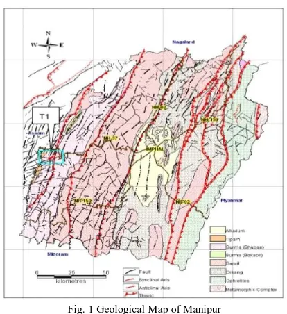
III. STUDY AREA AND GEOLOGY
A tunnel is being constructed for a railway line between Jiribam to Tupul sections in Manipur state under Northeast Frontier railways. The study area (T1 in Fig. 1) is located in Indo-Myanmar Range of Himalayan (IMR) system.
Fig. 1 Geological Map of Manipur
The whole rock types observed in the project area include Shale inter- beds of sandstones and siltstones. Sandstones inter-beds are generally medium grained and some horizons become siltstone but sandstone is dominant.
The natural terrain is very rugged with slopes frequently steeper than 40. The topography condition is such that overburden in the length of tunnel (3 km) varies from 0 to 300m. The sites lie within a category Zone-V seismic region with zone factor (Z) is 0.36 according to IS 1893:2002 [20].
IV. CHARACTERIZATION OF INTACT ROCK SAMPLES In order to evaluate properties of rock materials encountered in tunnels and study their effective parameters, seven intact rock samples were collected from different locations along the tunnel route. Unconfined compressive strength tests were conducted by the testing agency and the results along with GSI values are shown in Table I. The GSI values were obtained from the GSI chart for heterogeneous weak rock masses [15]. The rock mass was classified according to the Q-system, RMR method and GSI. Amongst them, the Q-system and RMR methods were used for rock support system design and GSI system was used for estimating design parameters [16]. Modulus of intact rock samples (Ei) was determined using equation (9) with MR value of 400 as per [19].
TABLEI INTACT ROCK PROPERTIES
Sample # UCS (σci)
(MPa)
GSI Ei (GPa)
1 19 18 7.6
2 35 20 14
3 48 23 19.2
4 72 26 28.8
5 96 28 38.4
6 100 59 40
Copyright to IJIRSET www.ijirset.com 121
The UCS of the intact rock samples varied from 19 to 118 MPa, while the elastic modulus of was from 7.6 GPa to 47.2 GPa. The unit weight of rock = 0.026MN/m3 has been considered in depth of 250 meters below ground level and Hoek-Brown material constant (mi) assumed 10 for lithified argillaceous rock such as siltstone, sandstone and shale [13].
V. RESULT AND DISCUSSIONS
To determine rock mass parameters from intact rock parameters, RocLab program [14], was used. This software is based on generalised Hoek-Brown failure criterion which yields values of strength (compression and tension), deformation modulus and shear strength parameters of the rock mass. Input parameters for the program are unconfined compressive strength (UCS) of the intact rock (σci), GSI, the petrographic material constant (mi), disturbance factor (D) and MR.
Rock mass parameters were obtained from different disturbance factors representing different levels blasting conditions. Three conditions: D= 0 (undisturbed in situ rock masses), 0.5 (partially disturbed in situ rock masses), and 1 (highly disturbed in situ rock masses) are adopted. The rock mass parameters for all the seven class of samples for different D values have shown in Tables II to IV, respectively.
TABLEII
ROCK MASS PARAMETERS FOR D=0
Sample #
Rock Mass Parameters
UCS (σc)
(MPa)
Deformation Modulus
(Erm)
(GPa)
Global Strength
(σcm)
(MPa)
Tensile Strength
(σt)
(MPa)
1 0.127 0.315 1.436 0.004
2 0.279 0.639 2.843 0.008
3 0.490 1.027 4.305 0.014
4 0.928 1.828 7.070 0.027
5 1.433 2.754 9.973 0.042
6 10.110 19.892 21.333 0.454
7 14.965 27.743 27.680 0.725
TABLEIII
ROCK MASS PARAMETERS FOR D=0.5
Sample #
Rock Mass Parameters
UCS (σc)
(MPa)
Deformation Modulus
(Erm)
(GPa)
Global Strength
(σcm)
(MPa)
Tensile Strength
(σt)
(MPa)
1 0.046 0.215 0.837 0.002
2 0.106 0.418 1.690 0.004
Copyright to IJIRSET www.ijirset.com 122 4 0.389 1.061 4.421 0.013
5 0.618 1.541 6.334 0.020
6 6.393 10.277 16.345 0.298
7 9.902 15.073 21.634 0.495
TABLEIV
ROCK MASS PARAMETERS FOR D=1
Sample #
Rock Mass Parameters
UCS (σc)
(MPa)
Deformation Modulus
(Erm)
(GPa)
Global Strength
(σcm)
(MPa)
Tensile Strength
(σt)
(MPa)
1 0.010 0.173 0.286 0.001
2 0.025 0.327 0.599 0.002
3 0.050 0.468 0.983 0.003
4 0.105 0.741 1.738 0.006
5 0.175 1.032 2.569 0.010
6 3.214 4.586 9.873 0.201
7 5.329 6.878 13.671 0.348
From the table it is observed that the rock mass parameters increase with increasing the intact rock parameters but they decrease with decreasing disturbance factor. For example, with GSI=23, σci= 48MPa and Ei= 19.2 GPa, estimated values of σc of 0.490, 0.106 and 0.050 MPa were obtained for the values of D of 0, 0.5 and 1 respectively.
0 20 40 60 80 100 120
0.00 0.02 0.04 0.06 0.08 0.10 0.12 0.14
N
or
m
li
ze
d U
C
S
(R
oc
k
M
as
s-U
C
S
/I
n
ta
ct
-U
C
S
)
Intact Rock-UCS (MPa) Disturabnce Factor(D)=0 Disturabnce Factor(D)=0.5 Disturabnce Factor(D)=1
Fig.2 Relation between normalized- UCS and intact rock-UCS
The Figure (2) depicts the obtained normalized rock mass-UCS (σc/σci) versus determined intact rock-UCS. It shows non-linear trend.
0 20 40 60 80 100 120
0 5 10 15 20 25 30
R
o
ck
M
as
s-G
lo
b
al
S
tr
en
g
th
(
M
P
a)
Intact Rock-UCS (MPa) Disturbance Factor(D)=0 Disturbance Factor(D)=0.5 Disturbance Factor(D)=1
Copyright to IJIRSET www.ijirset.com 123
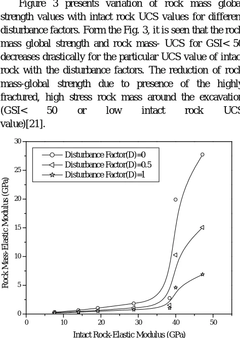
Figure 3 presents variation of rock mass global strength values with intact rock UCS values for different disturbance factors. Form the Fig. 3, it is seen that the rock mass global strength and rock mass- UCS for GSI< 50 decreases drastically for the particular UCS value of intact rock with the disturbance factors. The reduction of rock mass-global strength due to presence of the highly fractured, high stress rock mass around the excavation (GSI< 50 or low intact rock UCS value)[21].
0 10 20 30 40 50
0 5 10 15 20 25 30
R
o
ck
M
as
s-E
la
st
ic
M
o
d
u
lu
s
(G
P
a)
Intact Rock-Elastic Modulus (GPa) Disturbance Factor(D)=0
Disturbance Factor(D)=0.5 Disturbance Factor(D)=1
Fig.4 Relation between rock mass-elastic modulus and intact rock- elastic modulus
The Figure (4) depicts the non-linear trend between rock mass- elastic modulus and intact rock-elastic modulus. The deformability of rock mass will depends upon the both of intact rock and the discontinuities present within the rock mass. So that, the deformation modulus of rock mass decreases with decreasing with GSI value and intact rock
parameters (such as σci, Ei).
VI. CONCLUSIONS
Estimation of rock mass mechanical properties using intact rock parameters and other indices of rock mass was presented. From the details analyses conducted using RocLab software, the following conclusions are reached:
I. The mechanical properties of rock masses are function of the rock mass index values and intact rock strength parameters.
II. Rock mass parameters are in the order of only 2 to 10 % to that of intact parameters. The relation between various intact rock parameters and rock mass parameters showed nonlinear trends.
III. The intact rock GSI and UCS are the most dominant parameters to decide rock mass strength.
ACKNOWLEDGMENT
The authors thank the AECCOM India Private Limited and N.F. Railway official for allowing access to the data of Tunnel No. 1 in connection with Jiribam- Tupul New Railway Line Project in the State of Manipur.
REFERENCES
[1] Hoek, E. and Brown, E.T. (1980). “Underground Excavations in Rock.” London Institute of Mining and Metallurgy, London, UK, 1-536.
[2] Hoek, E. and Diederichs, M.S. (2006). “Empirical Estimation of Rock Mass Modulus.” International Journal of Rock Mech. & Mining sci.,43(2), 203-215.
[3] Hoek, E. and Brown, E.T. (1980). “Emprical Strength Criterion for Rock Masses.” J. Geotech. Engg. Div., ASCE, 106(9), 1013-1035.
[4] Griffith, A.A. (1924). “The Theory of Rupture.” in Proc 1st .Int. Congr. Applied Mech, Delft, 55-63.
[5] Bieniawski, Z.T. (1974). “Geomechanics Classification of Rock Masses and Its Application in Tunnelling.” Proc. 3rd International Congress Rock Mech., Denver, Part A, 27-32.
[6] Yudhbir, Lemanza W. and Prinzl, F. (1983). “An Empirical Failure Criteria for Rock Masses.” Proc. of the 5th International Congress Society of Rock Mech., Mellobourne, 1, B1-B8.
[7] Ramamurthy, T. (1994). “Strength Criteria fir Rocks with Tensile Strength.” Proc. Ind. Geotech. Conference, Warangal, India, 1, 411-414.
Copyright to IJIRSET www.ijirset.com 124 [9] Hoek, E. (1994). “Strength of Rock & Rock Masses.” ISRM, New
Journal, 2(2), 4-16.
[10]Hoek, E., Carranza-Torres, C. and Corkum, B. (2002). “Hoek-Brown Failure Criterion- 2002 Edition.” Proc. NARMAS-TAC Conference, Tornto, 1,267-273.
[11]Bieniawski, Z.T. (1973). “Engineering Classification of Rock Masses.” Trans S. Africa Institute Civil Engineers, 15(12), 44, 335.
[12]Barton, N., Lien, R. and Lunde, J. 1974. “Engineering Classification of Rock Masses for the Design of Tunnel Support.” Rock Mech.,
6(4), 189-236.
[13]Hoek, E. and Brown, E.T. (1997). “Practical Estimate of Rock Mass Strength.” International Journal of Rock Mech. & Mining sci.,34(8), 1165-1186.
[14]Rocscience Limited. (2011). “RocLab software ver: 1.032.” Toronto, Ontario, Canada.
[15]Hoek, E., Marions, P. and Benissi, M. (1998). “Applicability of the Geological Strength Index (GSI) Classification for Very Week and Sheared Rock Masses.” The Case of the Athens Schist Formation,
Bull. Engg. Geological Environment, 57(2), 151-160.
[16]Marions, P. and Hoek, E. (2000). “GSI- A Geologically Friendly Tools for Rock Mass Strength Estimation.” Proc. GeoEng2000 Conference, Mellobourne, 1422-1442.
[17]Deere, D.U. (1968). “Chapter 1: Geological Consideration.” Rock Mech. in Engineering Practice, (Ed. by K.G. Stagg & O.C. Zienkiewicz), Willey, New York, 1-20.
[18]Hoek, E. (1990). “Estimating Mohr-Coulomb Friction and Cohesion Values from the Hoek-Brown Failure Criterion.” International Journal Rock Mech. & Mining Sci. & Geomechanics, Abstracts,
12(3), 227-229.
[19]Hoek, E., Wood, D. and Shah, S. (1992). “A Modified Hoek-Brown Criterion for Jointed Rock Masses.” Proc. Rock Characterization, Symp. Institute Soc. Rock Mech., Eurock’92 (Edited by J.A. Hudson), British Geotech. Soc. London, 209-214.
[20]IS 1893(Part-I): General Provisions and Buildings, (2002). “Code for Practice Earthquake Design of Structures.” BIS, Fifth Revision, New Delhi.
[21]Kaiser, P.K., Diederichs, M.S., Martin, C.D., Sharp, J. and Steiner, W. (2000). “Underground Works in Hard Rock Tunnelling and Mining.” Proc. 4th Asian Rock Mechanics Symposium, Leung,