Error Correction and Detection of Source
Code Using High Level Synthesis of
Functional Verification
M.Maruthi1, R.Poovendran2
PG Scholar [VLSI Design], Department of ECE, Adhiyamaan College of Engineering, Hosur, TN, India1
Associate Professor, Department of ECE, Adhiyamaan College of Engineering, Hosur, TN, India2
ABSTRACT: A dynamic functional verification method that compares untimed simulations versus timed simulations for synthesizable [high-level synthesis (HLS)] behavioral descriptions. In Existing system, automatically inserts a set of probes into the untimed behavioral description. These probes record the status of internal signals of the behavioral description during an initial untimed simulation. These simulation results are subsequently used as golden outputs for the verification of the internal signals during a timed simulation once the behavioral description has been synthesized using HLS. In proposed method reports any simulation mismatches and accurately pinpoints any discrepancies between the functional Software (SW) simulation and the timed simulation at the original behavioral description (source code). This proposed method does not only determine where to place the probes, but is also able to insert different type of probes based on the specified HLS synthesis options in order not to interfere with the HLS process, minimizing the total number of probes and the size of the data to be stored in the trace file in order to minimize the running time. Results show that our proposed method is very effective and extremely simple to use as it is fully automate.
I. INTRODUCTION
.
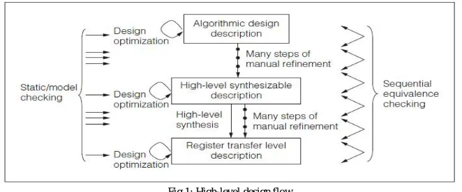
A high-level design flow that starts from an algorithmic design description. To enforce the correctness of various descriptions in such a design flow, we must resolve two issues. Eliminate bugs insofar as possible from the given description levels. This is necessary at the highest level of abstraction that cannot be verified via equivalence checking, but it is also necessary when equivalence checking cannot verify all the behaviors of a model by comparing it against a higher-level model.
Guarantee the equivalence of the two descriptions. We must guarantee equivalence of both a validated level model and of a lower-level model obtained automatically or through manual refinements of the higher-level model.
These two issues complement each other to assure the correctness of the descriptions as a whole. To eliminate bugs as much as possible from a given design description, simulation is not sufficient, especially for large and complicated designs. Therefore, we also use various formal methods to verify the design descriptions.
Fig 1: High-level design flow
II. RELATED WORK
STATIC ANALYSIS METHODS
from the beginning of the description. Whereas model-checking methods basically examine the design descriptions exhaustively starting from initial or reset states, static checking analyzes design descriptions only in small and local areas. Instead of starting from initial states, static checking first picks up target statements and then examines only small portions of design descriptions that are very close to those target statements, as shown in the left part of Figure.
Fig 2: Static checking and model-checking approaches
DEPLOYING SEC IN HLS FLOWS
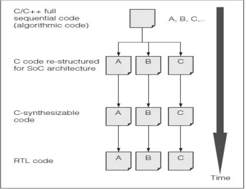
High-level synthesis generates an RTL description from a C/C++/SystemC model.1 By using HLS, adesigner’s development time is greatly reduced via coding at a higher abstraction level than RTL. However, to take advantage of system-level design andits time savings, formal verification between the twodesign descriptions is required. Verification helps reveal any bugs in HLS tools and permits any manual modifications at the synthesized RTL description. Figure 3 illustrates a working model in which an HLS tool is used. Algorithmic C/C++ models of the application(such as video codecs and wireless digitalbaseband modems) are the starting point. After manual hardware and software partitioning, blocks to beimplemented as IP blocks are individually split(A, B, C in the figure).
III. EXISTING SYSTEM
RTL DESIGN
Raising the level of abstraction in VLSI design has some distinct advantages over traditional register-transfer level (RTL) design methods. First, most of the designs start with a high-level model in order to validate the application to be implemented. High-level synthesis (HLS) provides a direct path between these models and RTL. It has been shown that one line of C-code translates into 7–10× more gates than RTL. This further implies that behavioral descriptions are easier to maintain and debug, and that fewer bugs will be introduced by designers. Second, in many cases, the design specifications are unstable and any changes in them can lead to major architectural changes (e.g., the use of on-die memory or external memory).
They address the issue of how to efficiently verify the functionality between an original untimed SW behavioral description and the synthesized design after behavioral synthesis. One of the main advantages of HLS is that it allows, in combination with model generators at different stages of the HLS flow, the reuse of the untimed test vectors used during the functional SW verification. Moreover, these model generators also allow using the SW simulation outputs as golden reference outputs for the timed Hardware (HW) verification. The main problem is that these test vectors only cover the inputs and outputs of the behavioral description. In case of mismatches, the user needs to start the debugging process. This is normally done by dumping the internal signals onto a Value Change Dump (VCD) file and manually verifying the waveform for any discrepancies. This poses serious problems to the designers.
PROBE INSERTION
One of the main contributions of this paper is to determine how and where to insert the probes and also the type of probe. A naïve method inserts a probe whenever an internal signal is being written to. This approach guarantees that the EDL is minimized at the expense of having to record and compare a very large number or probes. The number of probes inserted is important in order to exactly locate where the mismatch between the original behavioral description’s behavior and the synthesized descriptions happen. In order to determine the quality of the error detection mechanism, we define the term SCED.
SCED is the distance in terms of number of lines of source code between where the error is introduced in the system versus the first probe which detects this error. SCED differs from the traditional EDL normally used in post silicon verification. This is extremely important in larger designs, e.g., in multiprocessors systems where a bug we propose SCED as an index to measure the quality of a functional verification environment in HLS. The input to any HLS flow is a behavioral description, which is what needs to be modified to correct any errors detected. The smaller the distances in terms of lines of source code, the easier and faster it should be to locate the error.
It should be noted that modern HLS tools make aggressive use of static speculation techniques in order to reduce the latencies of control intensive applications. Some of these techniques include branch speculation and early conditional execution. This implies out-of-order execution. Nevertheless, data dependencies are still preserved, making our method still valid. During the experimental results, no problems due to code motion were observed. As mentioned previously, a naïve method inserts a probe after each assignment. This reduces the SCED to the minimum. The main problem with this approach is when the behavioral description includes arrays and loops, which are extremely common in high-level language descriptions. In this case, the number of outputs to be recorded can make this verification method infeasible as each of the array elements might need to be stored into separate files during each loop iteration and this again for each new simulation cycle.
DISADVANTAGES
IV. PROPOSED ARCHITECTURE
In this proposed system, a complete automated verification flow for synthesizable behavioral descriptions in order to detect where in the source code mismatches between the original untimed simulation and the timed synthesized design occur. In proposed verification flow leverages the latest verification features of commercial HLS tools, which allow th e reuse of transaction level test vectors for timed simulations. By automatically inserting a set of internal probes this method can efficiently detect mismatches between the untimed behavioral simulation and the synthesized circuit and locates where the error is introduced directly at the source code based on the distances between probes.
DYNAMIC EQUIVALENCE CHECKING
In order to reuse the original input stimuli and the untimed outputs as golden outputs, valid control signals for each input and output ports are created automatically. During cycle-accurate simulations, the timing of when data needs to be read and when a valid output is written needs to be made visible to the test bench. This verification method is also called dynamic equivalence checking (DEC), because it is possible to fully reuse the untimed input and output test vectors to compare the functionality of the initial untimed behavioral description and the synthesized timed circuit (either cycle accurate model or RTL). DEC contrast with the most extended formal equivalence checking, where typically a gate-netlistis compared with RTL, based on a canonical representation of both.
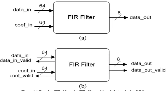
Fig 4: (a) Regular FIR filter. (b) FIR filter with valid signals for DEC.
• Fig (a)shows the block diagram of a finite-impulse response (FIR) filter with its data and coefficient ports and the data out port.
• Fig. (b) shows the valid signals generated automatically by the HLS tool in order to assert when an input signal is needed and when a valid output is generated.
• Here 9-tap FIR filter is used.
ADVANTAGES
V. LITERTURE SURVEY
The growing complexity of systems and their implementation into silicon encourages designers to look for ways to model designs at higher levels of abstraction and then incrementally build portions of these designs—automatically or manually—from these high-level specifications. Unfortunately, this translation process itself can be buggy, which can create a mismatch between what a designer intends and what is actually implemented in the circuit. Therefore, checking if the implementation is a refinement or equivalent to its initial specification is of tremendous value. In this paper, they present an approach to automatically validate the implementation against its initial high-level specification using insights from translation validation, automated theorem proving, and relational approaches to reasoning about programs.
During the HLS process, an engineer starts with a high level description of the design, usually called a specification, which is then refined into progressively more concrete implementations. Checking correctness of these refinement steps has many benefits, including finding bugs in the translation process, while at the same time guaranteeing that properties checked at higher levels in the design are preserved through the refinement process, without having to recheck them at lower levels. For example, if one checks that a given specification satisfies a safety property, and that an implementation is a correct trace refinement of the specification, then the implementation will also satisfy the safety property.
The novelty of our approach comes from the fact that it can account for concurrency which is inherent in hardware design. Our algorithm deals with this concurrency using standard techniques for computing weakest preconditions and strongest post conditions of parallel programs.
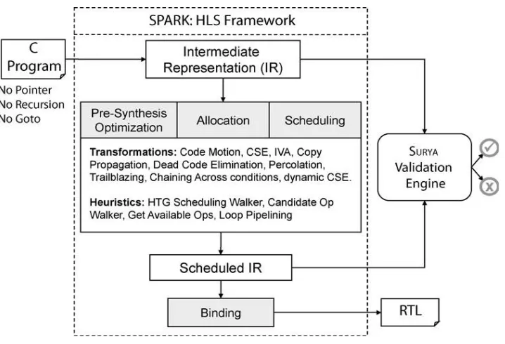
Fig 5: Overview of the Spark framework
THE APPLICATION OF PROGRAM VERIFICATION TECHNIQUES TO HARDWARE VERIFICATION
The growing complexity of machine designs and costs of engineering changes are increasing the demand for tools and methods to detect errors earlier in the hardware development cycle. Because of similar concerns in the development of software there has been a great deal of work on methods for proving that a program satisfies a given specification. This paper examines one such program verification technique, based on the notion of symbolic execution, and then explores its application to the problem of establishing the correct behaviour of a piece of hardware.
PROGRAM VERIFICATION
The problem is to establish confidence that a program will behave as expected. Ideally a programmer would like a proof of this fact. But to accomplish this, using the inductive assertion method, he must supply a significant amount of additional information.
SYMBOLIC EXECUTION
One can extend the definition of program execution to provide a symbolic execution in the same manner as one extends arithmetic over numbers to symbolic algebraic operations over symbols and numbers. Here inputs refers to any data external to the procedure, including those obtained through parameters, global variables, explicit read statements, etc. Symbolic value names should not be confused with symbolic variable names. A variable may take on different symbolic or non-symbolic values during a program’s symbolic execution, while a symbolic value name always refers to the same fixed but unknown value.
LOGIC VERIFICATION
nother level where verification certainly could be helpful is in proving that an implementation in terms of network of primitives (e.g. flip-flops and gates) satisfies a higher level specification. This specification could be written in one of the register transfer level languages, such as ISP or DDL.
HARDWARE UTILISATION RESULT
DURING SOFTWARE FAILURE
6
Mars, December 3, 1999 Crashed due to uninitialized variable
VII. CONCLUSION AND FUTURE SCOPE
A complete automated verification flow for synthesizable behavioral descriptions in order to detect where in the source code mismatches between the original untimed simulation and the timed synthesized design occur. Automatically inserting a set of internal probes our method can efficiently detect mismatches between the untimed behavioral simulation and the synthesized circuit and locates where the error is introduced directly at the source code based on the distances between probes.
Proposed system high level c language generates RTL code to check untimed simulation results. Propose a method for functional verification between untimed behavioral descriptions and timed verification in HLS. Extend the method to reduce the number of probes inserted in order to accelerate the simulation runtime and trace file size to be recorded.
REFERENCES
[1] H.R.Rategh et al., "A CMOS frequency synthesizer with an Ejected locked frequency divider for 5-GHz wirless LAN receiver," IEEE J Soli-State Circuits, vol. 35, no. 5, pp. 780-787, May 2016.
[2] P. Y. Deg et al., "A 5 GHz frequency synthesizer with an injection locked frequency divider and differential switched capacitors," IEEE Trans. Circuits Syst. I, Reg. Papers, vol. 56, no. 2, pp. 320-326, Feb. 2016.
[3] L. Lai Kan Leung et al., "A I-V 9.7-mW CMOS frequecy synthesizer for IEE 802.lIa transceivers," IEEE Trans. Microw. Theor Tech., vol. 56, no. I, pp. 39-48, Jan. 2014.
[4] M. Alioto and G. Palumbo, Model and Design of Bipolar and MOS Current-Mode Logic Digital Circuits. New York: Springer, 2013.
[5] Y. Ji-ren et al., "Atue single-phae-clock dynamicCMOScircuit technique," IEEE J Solid-Statem Circuits, vol. 24, no. 2, pp. 62-70, Feb. 2009.
[6] S Pellerno et aI., "A J3.5-mW 5 GHz frequenc synthesizer with dyamic-logic frequency divider, " IEE J. Solid-State Circuits, vol. 39, no. 2, pp. 378-383, Feb. 2007.