Fault Tolerance Techniques for
Combinational Circuits
Ambiga.R1, Elizabeth Rani.T2, Gayathri.B3, Haritha.P. S4 and Vijay Murugan.S5
UG Scholar, Department of ECE, Adhiyamaan College of Engineering, Hosur, TN, India1,2,3,4
Associate Professor, Department of ECE, Adhiyamaan College of Engineering, Hosur, TN, India5
ABSTRACT: Increasing in soft error rates, the multiple faults is needed to be considered while modeling circuit sensitivity and evaluating fault tolerance techniques. This paper proposed a design of combinational circuits for soft error tolerance with minimal area overhead. This is based on analyzing random pattern testability of faults in a design and protecting sensitive transistors, whose probability of soft error is relatively high. Transistors are protected by duplicating and sizing a subset of transistors for the protection of sensitive transistors. The proposed method compares the power and output accuracy using Quad technique and STR (Selective Transistor Redundancy) algorithm.
KEYWORDS: STR algorithm, Soft Error, Quad algorithm, Triple Modular Redundancy (TMR), Combinational Circuits, Tanner Tools.
I.INTRODUCTION
Soft errors are transient errors that cause incorrect operation of a digital circuit. To reduce the error algorithms are used. In this paper, STR and quad algorithms are used to compare the power analysis. Shrinking of device size leads to soft error increase. Fault tolerance techniques cannot be designed with 100% accuracy without increasing design cost. The TMR is the most popular SET mitigation. The SET have a major impact on circuit operation, and they should be treated properly.Triple modular redundancy is one of the possible fault tolerance technique that can be applied to a each logic element is triplicated.
II.RELATEDWORK
Kartik Mohanram, et al [1] presents a new methodology for designing logic circuits with partial error
circuits designed with DMR logic show a 10–24% area improvement for flip-flop designs, and a 33% improvement for latch designs.
III.SOFTWARE USED
Tanner 13.0 is used for the proposed method. Tanner tools is a Spice Computer Analysis programmed for Analogue Integrated Circuits. Tanner tool consists of the following Engine Machines:
S-EDIT(Schematic Edit)
T-EDIT(Simulation Edit)
W-EDIT(Waveform Edit)
L-EDIT(Layout Edit)
Using these engine tools, spice program provide facility to the use to design & simulate new ideas in Analogue Integrated Circuits before going to the time consuming & costly process of chip fabrication.
Schematic edit tools (S-EDIT)
S-Edit is hierarchy of files, modules & pages. It introduces symbol model & schematic modes.
Circuit simulator (T-SPICE)
T-Spice Pro’s waveform probing features integrats S-Edit ,T-spice & W-Edit to allow individual points in a circuit to be specified and analyzed. The heart of T-spice operation is the input file.
Waveform edit (W-EDIT)
The ability to visualize the complex numerical data resulting from VLSI circuit simulation is critical to testing, understanding & improving these circuits. W-Edit is a waveform viewer that provides ease of use, power & speed in a flexible environment designed for graphical data representation.
Layout (L-EDIT)
It is a tool that represents the masks that are used to fabricate an integrated circuit. It describes a layout design in terms of files, cells & mask primitives. On the layout levels, the component parameters are totally different from schematic level.
IV. FLOW DIAGRAM
The flow diagram of the proposed technique is shown in Fig.1. The CMOS circuit is designed for the respective logic gates using STR and Quad algorithm and then the power analysis is made at the output.
Combinational Circuit Design in Tanner
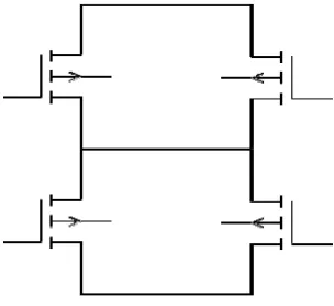
Combinational logic is a type of digital logic which is implemented with Booleans circuit, whose outputs is the pure function of present inputs. The basic NAND gate CMOS structure is represented in the Fig 2(a). NAND and NOR gates are universal gates. NAND gate is more efficient and low leakage circuit when compared to NOR.
Fig 2 Basic CMOS NAND structure
STR Algorithm
The Selective Transistor Redundancy technique(STR) is applied to protect the transistor that have relatively high Probability Of Failure(POF) different arrangement of nMOS and pMOS transistors are designed for each gate for various transistor protection.
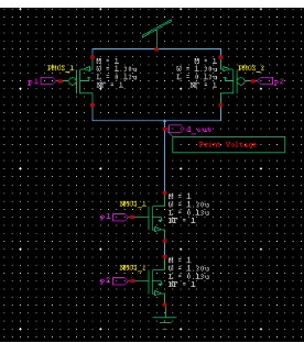
Fig 3 Basic STR structure for a transistor
Fig 4 STR NAND structure
QUAD Algorithm
The quadded algorithm uses four transistors for the function of the single transistor. An error in a single transistor can be stood by the quadded transistor. Many double errors can be tolerated as they do not occur in transistors placed in parallel the quadded transistor makes the circuit slower with an area overhead.
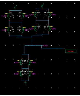
Fig 5 Basic Quadded structure for a transistor
Fig 6 Quadded NAND structure
V.EXPERIMENTAL RESULTS
The results obtained using the proposed algorithms is analyzed and tabulated in the fig.3. The quadded structure improves the reliability. The power analyze is done for both the algorithm.
Table 1 Power analyses of the algorithms
VI.CONCLUSION
The results of this algorithm shows that the STR algorithm consumes more power when compared to Quad algorithm. But when we comes to area overhead STR algorithm is efficient than Quad algorithm and Quad is not effective for simple primary circuits.
REFERENCES
[1] Kartik Mohanram and Nur A. Touba (2003), “Partial Error Masking to Reduce Soft Error Failure Rate in Logic Circuits” 18th IEEE
International Symposium on Defect and Fault Tolerance in VLSI Systems.
Fault Tolerance Algorithm Power analyze
(watt)
STR algorithm P1=
1.45e^-8
P2= 4.852e^-8
Quadded algorithm P1=
1.05e^-8
[2] Christian J. Hescott, Drew C. Ness and David J. Lilja (2007), “Scaling Analytical Models for Soft Error Rate Estimation Under a
Multiple-Fault Environment” 10th Euromicro Conference On Digital System Design Architectures, Methods and Tools.
[3] Warin Sootkaneung and Kewal K. Saluja(2010), “On Techniques for Handling Soft Errors in Digital Circuits” IEEE International
Test Conference.
[4] John Teifel(2008), “Self-Voting Dual-Modular Redundancy Circuits for Single-Event-Transient Mitigation” IEEE Transactions On
Nuclear SCIENCE, Vol. 55, No. 6.
[5] Aiman H. El-Maleh and Khaled A. K. Daud (2015), “Simulation-Based Method for Synthesizing Soft Error Tolerant Combinational
Circuits” IEEE Transactions On Reliability.
[6] Ahmad T. Sheikh, Aiman H. El-Maleh, Muhammad E. S. Elrabaa, and Sadiq M. Sait(2016), “A Fault Tolerance Technique for