Comparison on the Effect Of Regenerative and
Sub Cooling in the Heat Transfer Characteristics
of Semi Cryogenic Thrust Chamber Having
Rectangular Cooling Channels by Using CFD and
Numerical Analysis
Sarath Raj
1, AswaniRajan
2Assistant Professor, Dept. of Mechanical Engineering, Sree Narayana Institute of Technology, Kerala India1 Assistant Professor, Dept. of Electrical and Electronics Engineering, Sree Narayana Institute of Technology, Kerala,
India2
ABSTRACT:In this paper, Computational Fluid Dynamics and Numerical Analysis is used to investigate the rocket thrust chamber cooling characteristics. The scope of the investigation involves the study of effect of regenerative and sub cooling on the heat transfer characteristics of coolant channel. Steady state pressure based analysis is carried out in this work. The temperature distributions of coolant along the rectangular cooling channel, temperature distributions of copper and stainless steel walls are the main focus of the study. In this study the, the coolant (kerosene), which is the fuel) enters at the aft end of the thrust chamber and passes through the rectangular cooling channels before it is fed to the injectors.
KEYWORDS:Computational Fluid Dynamics, Numerical Analysis, Thrust Chamber, Rectangular Cooling Channel.
I. INTRODUCTION
All rocket engines have one problem in common; high energy released by combusted gases. This problem results in high combustion temperatures in the order of 2400K to 3600 K, high heat transfer rates (0.8 to160 MW/m2) in thrust chamber and therefore requires special cooling techniques for the engine. Cooling techniques developed to cope with this problem, either singly or in combination, include regenerative, radiation, sub cooling, film cooling or transpiration cooling, ablation, arid inert or endothermic heat sinks. To choose the proper cooling technique mission requirements, environmental requirements and operational requirements should be considered. Regenerative cooling is one of the most widely applied cooling techniques used in liquid propellant rocket engines.
II. LITERATURE REVIEW
Mary F. Wadel[1] did an analytical investigation on the effect of high aspect ratiocooling channels, by considering different channel designs, on hot-gas-side wall temperature and coolant pressure drop for liquid hydrogen cooled rocket combustion chamber.Coolant channel design element considered were; length of combustion chamber in which high aspect ratio(height/width) cooling was applied, number of coolant channels. And coolant channel shape. Daniel K.Parris and D. Brian Landrum[2] determined the flow field characteristics in a coolant channels by the use of a commercial CFD and metaphysics software developed by CFD Research Crop called CFD-ACE+.The channels are characterized by high Reynolds number, varying aspect ratio, varying curvature, asymmetric and symmetric heating. The supercritical hydrogen is used as coolant for their analysis. MichealL.Meyer[3] conducted an experiment on a series of electrically heated tube to investigate the effect of high aspect ratio on the curvature heat transfer enhancement in uniformly heated rectangular cooling passages. Three hardware geometry were tested; a base line straight aspect ratio 10 tube, an aspect ratio 1(square) tube with 45o curve, and an aspect ratio 10 tube with a 450 curve. Gaseous nitrogen is used as coolant. C. L. Mercle, D. Li,and V.Sankaran[4] discussed the use of detailed CFD modelling for the description of cooling in rocket chambers. The overall analysis includes a complete three-dimensional analysis of the flow in the regeneratively cooled passages, conjugate heat transfer in the combustor wall, and the effect of film cooling on the inside chamber. Representative results for the cooling passages are presents showing the effect of heat conduction in the copper walls with tube aspect ratio of 1.5:1.
III.PROBLEM SOLVING WITH CFD
In solving fluid flow problems we must be aware that the underlying physics is complex and the results generated by a CFD code are at the best as good as the physics and chemistry embedded in it and at worst as its operator. Prior to setting up and running a simulation using CFD software there is a stage of identification and formulation of the problem in terms of its physical and chemical phenomena that need to be considered. Over 50% of time spent in industry on a CFD project is devoted for defining the domain geometry and for grid generation.
IV.COMPUTATIONAL FLUID DYNAMICS SIMULATION
The design, scalability, and running of unit operations in chemical process industries rely heavily upon empiricism and correlations of overall variables for non-ideal or non-equilibrium conditions. Many equipment designs in use are based on the past experience of experts applying rules of thumb, resembling art more than science. Processes that are sensitive to the local phenomena and the reactant concentrations are often difficult to design or scale up, because the design correlations do not take local effects into account. Non-idealities introduced by scaling up of lab or pilot scale equipment are difficult, if not impossible to predict accurately.
and better user interfaces now enables non-experts to use CFD as a design tool on day-to-day basis. As a consequence, CFD has progressed from the domain of mainframe to the high-end engineering workstation and even to laptop PCs.
V. MODELLING
For aspect ratio5 channel dimensions are height of the channel is 3mm, width 0.6mm and rib width is 2.3mm.
Fig. 1. Channel dimensions.
VI.GRID GENERATOR
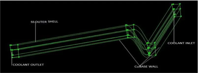
GAMBIT 2.4.6 is used for modelling and grid generation. FLUENT 6.3.26, a pressure based segregated solver, is used for the analysis. Standard k-ε two-equation turbulence model is employed with standard wall functions. SIMPLE algorithm is used to get the pressure field .The computational domain consists of one fluid and two solid domains. The fluid domains include coolant (kerosene) which flows through the rectangular channels provided on the surface. The solid domains include inner copper shell and stainless steel outer covering.
Fig. 2. Selected sectors with boundary conditions
Fig.3. Grid display of the computational domain, aspect ratio 5
The total mass flow rate of the kerosene (coolant) through all the channels is 7.57 kg/s and the temperature at the inlet is 300K.Pressure outlet of 1bar is used for the outlet zone of coolant. The outermost wall of stainless steel covering is assumed to be adiabatic. The lower base copper wall is split into three sections and heat transfer coefficients at each of the section of the base wall is calculated by using Bartz Equation and CEA coding and the heat transfer coefficient thus obtained is applied on the base copper wall as boundary condition. In the case of regenerative cooling with sub cooling the inlet temperature of coolant reduces to 293K.
VII. RESULTS AND DISCUSSIONS
1.NUMERICAL ANALYSIS
(i) Aspect Ratio 5. (Regenerative cooling only)
Equations used
hg = 0.026 d t0.2
μ g 0.2Cpg P rg0.6
P c C ∗
0.8A t A
0.9
σ (1)
Where,
σ = 0.5Twg
T𝑐 1 +
𝛾−1
2 𝑀
2 + 0.5 −0.68 1 +𝛾−1
2 𝑀
2 −012 (2)
𝑄convective =hg Taw−Tag (3)
Taw = Tc
1+r γ −12 M2
1+ γ −12 M2 (4)
Where,
𝑟 = (Pr)0.33For turbulent flows.
hg=heat transfer coefficient
Pr=Prandtl number
PC=Chamber pressure
Taw=Adiabatic wall temperature K
Tc=Combustion temperature K
I.CHAMBERSECTION
Substituting the values of μg, Prg, Cpg,C∗ in Bartz equation
hg= 14563.92 W/m2K
Adiabatic wall temperature, by using equation (4) Taw = 3656 K
Heat Flux
From equation (3)
Qconvective= 43.06468×10⁶ W/m2
II)THROATSECTION
Substituting the values of μg, Prg, Cpg,C∗ in Bartz equation
hg= 23656.746 W/m 2
K
Adiabatic wall temperature, by using equation (4) Taw = 3491.85 K
Heat Flux From equation (3)
Qconvective= 64.05×10⁶W/m2
III)EXITSECTION
Substituting the values of μg, Prg, Cpg,C∗ in Bartz equation
hg= 4821.287 W/m2K
Adiabatic wall temperature Taw, by using equation (4) Taw = 5786.89 K
Heat Flux
From equation (3)
Qconvective= 25.4896×10⁶W/m2
(ii) Aspect Ratio 5. (Sub cooling considered)
By using equations (!), (2), (3), (4)
Heat transfer coefficient at the chamber section H chamber=6378.359124W m2K
Heat Flux
=6378.35912(3656─570.64)
=19.679× 10⁶𝑊
𝑚2
Heat transfer coefficient at the throat section H throat =10360.6187W m2K
Heat Flux
qconvective =hg Taw−Tag
=10360.6187(3491.85─682) =29.1118× 10⁶𝑊
𝑚2
Heat transfer coefficient at the exit section Hexit =2111.5W m2K
Heat Flux
qconvective =hg Taw−Tag
=2111.5(5786.89─350) =11.4804× 10⁶𝑊
𝑚2
2. CFD Analysis
The temperature distributions of coolant along the coolant channel, temperature distributions of copper and stainless steel walls are the main focus of the study. For the rectangular channel with aspect ratio 5 the, the coolant(kerosene which is the fuel) enters at the aft end of the thrust chamber and passes through the rectangular cooling channels before it is fed to the injectors,(Single regenerative circuit). The following are the results obtained in the analysis.
(i) Aspect Ratio 5. (Regenerative cooling only)
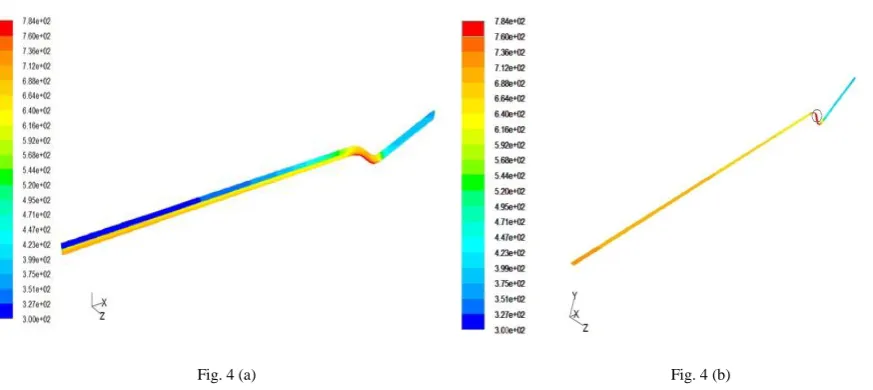
Fig. 4 (a) Fig. 4 (b)
Fig.4 (a) Three-dimensional schematic of computational domain and converged contour for total temperature.Fig.4 (b) Temperature contour of Cu base wall.
investigate the coolant temperature, coolant enthalpy, coolant velocity and hot gas and coolant side wall temperatures to obtain the effectiveness of the cooling circuit.
Fig. 5 (a) Fig. 5 (b)
Fig.5 (a) Contour of coolant temperature.Fig.5 (b) Coolant temperature distributions
Figure 5 (a) is the contour of coolant temperature and figure 5 (b) shows the coolant domain inside the rectangular channel. From Figure 5 (b) it is clear that coolant enters into the channel at temperature of 300K and is heated up to a maximum temperature of 510K which is well below the coking temperature of kerosene. Generally coking temperature for RP-1 ranges from 561-727K. The slope of the line is an indication of the amount of heat absorbed by the coolant along the axial length of the section. The slope is almost constant, except for small portion of the throat, where the heat flux is the maximum. The reason for the smooth increase of the coolant temperature along the cooling channel is the overall heat flow (product of heat flux and area) remains constant.
Fig. 6 (a) Fig. 6 (b)
Fig. 6 (a) Temperature contour of Stainless steel top wall. Fig. 6(b) Temperature distribution of Stainless steel top wall
(ii) Aspect Ratio 5. (Sub cooling considered)
Fig. 7 (a) Fig. 7 (b)
Fig. 7 (a) Three-dimensional schematic of computational domain and converged contour for total temperature for aspect ratio 5 with sub cooling. Fig. 7 (b) Temperature contour of Cu base walls.
Figure 7 (a) shows that by considering sub cooling of the coolant to 293K the maximum temperature reached is 682K, ie studies shows that by comparing the regenerative cooling temperature reduced by 102K and ,so by sub-cooling to both coolant outlet and coolant inner wall temperature can be reduced. Figure 7 (b) shows the base copper wall temperature distribution. The maximum temperature 682K observed is at the throat portion and the graph shows the temperature distribution of Cu wall along the axial position of the thrust chamber
Fig.8. Contour of coolant temperature.
Fig. 9 (a) Fig. 9 (b)
Fig. 9 (a) Contour of Stainless steel top wall. Fig. 9 (b) Temperature distribution of Stainless steel top wall
Figure 9 (a) shows the temperature contour of stainless steel top wall and figure 9 (b) shows the temperature distribution of stainless steel when considering sub cooling and the maximum temperature obtained is 617K
VIII. CONCLUSION
The effectiveness of regenerative cooling of thrust chamber is carried out by considering aspect ratio 5. Regenerative and sub cooling studies show that the wall temperatures are decreasing down into acceptable material limit at the hot gas side. Coolant temperature and coolant velocity are also shown to be in the acceptable region. The analysis shows that coolant side wall temperature tends to exceed the coking limit at the throat region. This may lead to the deposition of solid deposits within the coolant channels since kerosene, which is a hydrocarbon based fuel is used as the coolant. But by adopting sub cooling and increasing the aspect ratio of the coolant channels, reduced the coolant side wall temperature below the coking limit and hence it avoids the likelihood of coking in the coolant channel.
REFERENCES
[1] Mary F. Wadel, “Heat Transfer in Rocket Combustion chambers”, N 94-20041, SECA.Vol.2,pp 99-108.
[2] C. L. Merkle, D. Li and V. Sankaran, “Analysis of Regen Cooling in combustion Chambers.”, NASA Space Act Agreement, NCC8-200. [3] Daniel K.Parris and D. Brian Landrum, “Regenerative Cooling for Liquid rocket Engines”, Journal of Thermal Science Vol.4, No.1, pp. 54-59.
[4]MichealL.Meyer, “Advanced Rocket Engines” ,AIAA-2004,NATO OTAN- 74239.
ACKNOWLEDGMENT
The authors thank the Managing Director Sree Narayana Institute of Technology Adoor, Kerala for giving the financial assistance and Head of the Department, Mechanical Engineering Sree Narayana Institute of Technology Adoor, for giving valuable guidance and suggestions.
BIOGRAPHY