ABSTRACT
BOEHM, RYAN DANIEL. Microscale Material Processing for Drug Delivery and Biosensing Applications. (Under the direction of Dr. Roger J. Narayan.)
Rapid prototyping and additive manufacturing techniques have become more prevalent in recent years and their use in microscale medical device fabrication is of interest. In this thesis, a variety of rapid prototyping and microscale fabrication techniques are investigated to determine if they can be utilized in the creation of polymeric microneedle devices for drug delivery and biosensing applications. The photopolymerization technique dynamic mask microstereolithography is investigated to this end. Micromolding replication of structures created from this photopolymerization technique is highlighted. Furthermore, a combination of injection molding and drawing lithography are utilized for manipulation of a thermoplastic polymer material for microneedle fabrication. Inkjet printing, which is a noncontact deposition technique, is investigated as a means of applying surface coatings of therapeutic agents to microneedle arrays.
iii with multiphoton microscopy. Microneedle arrays created out of PMVE/MA using the combination of dynamic mask microstereolithography and soft lithography were modified by inkjet printed drug coatings. Piezoelectric inkjet printing was utilized to deposit the antifungal drugs amphotericin B and miconazole onto the surfaces of the microneedles. The antifungal properties of the drug coatings on the microneedle arrays were assessed
Microneedle arrays were also fabricated by using a combination of injection molding and drawing lithography out of the biodegradable polymer, poly(glycolic acid) (PGA). Surface coatings of voriconazole (antifungal agent) were applied to the microneedle arrays using piezoelectric inkjet printing. Examination of the microneedles and print coatings with microscopy, energy dispersive x-ray spectrometry, and Fourier transform infrared spectroscopy were conducted. Assessment of the porcine skin penetration by the microneedle arrays and the antimicrobial properties of the inkjet-modified arrays with agar plating studies were conducted. Modification of this technique was undertaken to create microneedle devices with multiple surface coatings. Drug release layers were applied to the microneedles with inkjet printing, followed by deposition of the poorly aqueously soluble drug, itraconazole. These devices were assessed for the chemical composition of the print-coatings, antimicrobial properties, and penetration into skin.
© Copyright 2015 by Ryan Daniel Boehm
Microscale Material Processing for Drug Delivery and Biosensing Applications
by
Ryan Daniel Boehm
A dissertation submitted to the Graduate Faculty of North Carolina State University
in partial fulfillment of the requirements for the Degree of
Doctor of Philosophy
Biomedical Engineering
Raleigh, North Carolina 2015
APPROVED BY:
_________________________ _________________________
Dr. Albert Banes Dr. Gary Gilleskie
_________________________ _________________________
Dr. Roger Narayan Dr. Harold Pillsbury
Chair
_________________________
ii DEDICATION
iii BIOGRAPHY
Ryan D. Boehm was born on January 16, 1985 in Port Jefferson, New York to parents Barbara and Ronald Boehm. He moved with his family to the Cary, North Carolina in the summer of 1993, where he attended the remainder of elementary, middle, and high school. Ryan graduated from Green Hope High School in 2003 and started his undergraduate studies at North Carolina State University in the fall of that same year. He started off his curriculum in the First Year College program, but after deliberating on his options, matriculated into Biomedical Engineering. He completed his undergraduate degree with a B.S. in Biomedical Engineering in the spring of 2008. During the final two years of his degree, he interned at Inspire Pharmaceuticals, Inc., gaining hands-on benchtop experience in a research lab, which helped him to gain interest in the research setting.
iv ACKNOWLEDGEMENTS
I would like to thank Dr. Roger Narayan for providing me with the
opportunity to work in his lab on these projects over the last 6-plus years. I have had the opportunity to work in Raleigh at NCSU, travel to Germany to LZH, California to Sandia National Labs, and Maryland to the FDA, during the course of my studies. It has been a very collaborative experience over the course of my
graduate career, and he has facilitated these opportunities. I would also like to thank him for being the chair of my committee, as well as Dr. Albert Banes, Dr. Gary Gilleskie, Dr. Harold Pillsbury, and Dr. Behnam Pourdeyhimi for participating as members of my committee. Thank you for the support and feedback.
The NCSU community and the BME department, as a whole, have been a huge
part of my education for over a decade. I started at NCSU in 2003, joining the BME department a few years later, and this community has been a steady influence in my life over that time period. Thank you to the endless list of people with whom I have interacted and learned from over the course of my time in the program. It has been a very meaningful journey.
To all of my labmates over the past several years, thank you for your support and friendship. We have done a lot of work and shared a lot of laughs along the way. Particularly, thank you to Shelby Skoog and Phil Miller. You were always there for me to bounce an idea off of, provide technical help and insight, but even more so, were there to encourage, listen, and laugh. I value the friendships we’ve formed
v
To all of my friends, including Josie Bodle, Brett Hartsfield, Erin Jerkins, Hayley Dirscherl, Matt Jones, April Grissom, Pam Porter, Andy Porter, Meggan
Masters, Ashley Jones, Brandon Jones, everyone from my years on the kickball team, and everyone who I’m unfortunately forgetting at the moment, thank you for your support and encouragement over the years. It has meant a lot and I truly appreciate the time we’ve spent as you helped me along the way.
To Katie, thank you for your support and patience as I’ve worked long hours and traveled between different states to finish my degree. I know it has not been easy, but you have been very supportive and encouraging during the process. It means a lot that you have stuck by my side through a challenging and rigorous time in my life.
And lastly, thank you of course to my family. Mom, Dad, Kevin, Stephen, and all of my extended family, you have been invaluable in helping me continue with my education and work toward earning my degree. You have always been there to support, encourage, and help anyway that you could and in any way that I have needed. I would not have been able to do this without you and I’m truly grateful for
vi TABLE OF CONTENTS
ACKNOWLEDGEMENTS ... iv
LIST OF TABLES ... ii
LIST OF FIGURES ... iii
Chapter 1 Introduction ...1
Microneedle Background ... 2
Dynamic Mask Microstereolithography ... 4
Two-photon Polymerization ... 5
Injection Molding/Drawing Lithography ... 7
Inkjet Printing ... 7
References ...10
Chapter 2 Piezoelectric Inkjet Printing of Medical Adhesives and Sealants ... 12
Abstract ...13
Introduction ...14
Piezoelectric Inkjet Printing ...15
Preparation of Medical Adhesives and Sealants ...16
Conclusion ...24
References ...26
Chapter 3 Modification of Microneedles Using Inkjet Printing ... 29
Abstract ...30
Introduction ...31
Experimental Procedure ...38
Results and Discussion ...44
Conclusion ...49
References ...52
Chapter 4 Indirect Rapid Prototyping of Antibacterial Acid Anhydride Copolymer Microneedles ... 56
Abstract ...57
Introduction ...58
Experimental Procedure ...61
Results and Discussion ...67
Conclusions ...73
vii Chapter 5 Inkjet Printing of Amphotericin B onto Biodegradable Microneedles Using
Piezoelectric Inkjet Printing ... 77
Abstract ...78
Introduction ...79
Materials and Methods ...84
Results and Discussion ...91
Conclusions ...92
References ...94
Chapter 6 Inkjet Printing for Pharmaceutical Applications ... 98
Abstract ...99
Introduction ... 100
Results and Discussion ... 109
Conclusions ... 113
References ... 114
Chapter 7 Polyglycolic Acid Microneedles Modified with Inkjet-Deposited Antifungal Coatings ... 117
Abstract ... 118
Introduction ... 119
Materials & Methods ... 122
Results and Discussion ... 129
Conclusions ... 139
References ... 141
Chapter 8 Inkjet Deposition of Itraconazole onto Poly(glycolic acid) Microneedle Arrays ... 143
Abstract ... 144
Introduction ... 145
Materials & Methods ... 147
Results & Discussion ... 153
Conclusion ... 164
References ... 165
Chapter 9 Microstereolithography-Fabricated Microneedles for Fluid Sampling of Histamine-Contaminated Tuna ... 167
Abstract ... 168
Introduction ... 169
viii
Fish Preparation ... 173
Histamine Testing Procedure... 174
Results & Discussion ... 175
Microneedle and Test Holder Fabrication ... 175
Comparison of Testing Methods with Histamine-Spiked Tuna Samples ... 176
Conclusion ... 182
ii LIST OF TABLES
Table 8.1: Overview of the parameters utilized for inkjet deposition onto PGA
microneedles………. 149
iii LIST OF FIGURES
Figure 1.1: DLP schematic. a) Lamp light source b) Digital Mirror Device (DMD) c) Focusing lens d) 45˚ mirror e) Photoinitiated resin vat f) Build platform – Adapted from [5] – Fig. 1, pg. 67. ... 4 Figure 1.2: “Scheme of the 2PP fabrication setup.” From [9] – Fig. 2, pg. 57. ... 6 Figure 2.1: Scanning electron micrographs of CoSeal® material inkjetted in circular pattern
on Si (111) substrates. Microscale Patterning of Two-Component Biomedical Hydrogel, A Doraiswamy, R Crombez, WDA Shen, YS Lee, RJ Narayan, Journal of Adhesion, 86 (1): 62-71, 2010. Reprinted by permission of the publisher (Taylor & Francis Group, http://www.informaworld.com). ...17 Figure 2.2: Phase contrast optical micrograph of array of Vetbond™ n-butyl cyanoacrylate
adhesive on a glass microscope slide...19 Figure 2.3: Primary amino acid sequence of Mefp-1, Mefp-3, and Mefp-5 mussel adhesion
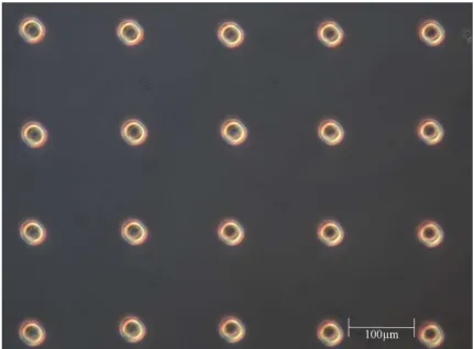
proteins. A, K, P, S, Y, T, G, N, R, W, E, L are the single letter notations for the amino acids alanine, lysine, proline, serine, tyrosine, threonine, glycine, asparagine, arginine, tryptophan, glutamic acid, and leucine, respectively. Reprinted from J.H. Waite, Adhesion a la moule, Integrative and Comparative Biology, ©2002, 42, 6, 1172-1180, by permission of The Society for Integrative and Comparative Biology. ...20 Figure 2.4: Optical micrographs of mussel adhesive protein solution inkjetted into
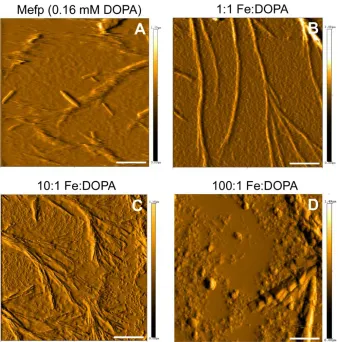
microarray and line patterns. Reprinted from A Doraiswamy, TM Dunaway, JJ Wilker, RJ Narayan, Inkjet Printing of Bioadhesives, Journal of Biomedical Materials Research Part B-Applied Biomaterials, 89B (1): 28-35, 2009 by permission of the publisher. ...21 Figure 2.5: Topography-flattened atomic force micrograph of inkjetted mussel adhesive
protein, 1:1 Fe:DOPA, 10:1 Fe:DOPA, and 100:1 Fe:DOPA structures. Scale bar equals 10 m. Reprinted from A Doraiswamy, TM Dunaway, JJ Wilker, RJ Narayan, Inkjet Printing of Bioadhesives, Journal of Biomedical Materials Research Part B-Applied Biomaterials, 89B (1): 28-35, 2009 by permission of the publisher. ...22 Figure 2.6: Average strength of bioadhesives inkjetted on full thickness porcine skin. All
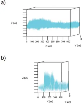
iv Figure 3.4: Scanning electron micrographs of an unmodified Gantrez® AN-139 microneedle and a quantum dot-coated Gantrez® AN-139 microneedle. (a) Scanning electron micrograph of an individual unmodified Gantrez® AN-139 polymer microneedle. (b) Scanning electron micrograph of an individual quantum dot-coated Gantrez® AN-139 polymer microneedle. The longitudinally cut surface of the coated microneedle exhibited crater-like features, which were attributed to hydrolysis of the Gantrez® AN-139 polymer by the quantum dot solution. Sodium chloride crystal precipitation from phosphate buffered saline solution was observed on the coated microneedle surface. .48 Figure 3.5: Maximum projections (in red) rendered from acquired z-stack multiphoton
images of quantum dot delivery into porcine skin. (a) Topically applied quantum dots one hour after application. The skin was oriented with the stratum corneum at the top of the imaging window. (b) A single microneedle one hour after application. The image was oriented with the microneedle and the stratum corneum at the bottom of the imaging window. In these figures, the spacing between the bars on the Z-axis is 50 µm. Inversion of the colors was performed to facilitate viewing. ...49 Figure 4.1: Key steps in processing Gantrez®AN 169 BF microneedle arrays by means of
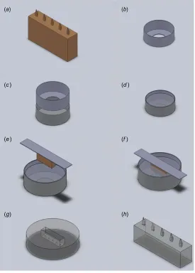
visible light dynamic mask micro-stereolithography-micromolding. (a) Master structures were fabricated out of eShell 200 using visible light dynamic mask micro-stereolithography. (b) To create micromolds, vessels for holding polydimethylsiloxane resin were fashioned out of 20 mm diameter aluminum crimp top washers. (c) Aluminum foil was used to wrap the crimp top washers and seal them for application of polydimethylsiloxane resin. (d) Once sealed, polydimethylsiloxane resin was added to the crimp top washer vessels. (e) The eShell 200 master structures were attached to strips of aluminum using a cyanoacrylate adhesive, Loctite® 404TM. The master arrays were then lowered into the unpolymerized polydimethylsiloxane resin. ( f ) The aluminum strips, which held the master arrays, were placed on the edges of the crimp top washers. These constructs were then placed on a 125 ◦C hotplate for 10 min to facilitate polymerization of the polydimethylsiloxane resin. (g) The master structures were removed from the newly fabricated micromolds using forceps. The aluminum washers and foils were subsequently peeled off of the polydimethylsiloxane micromolds. The micromolds were then filled with an aqueous gel material containing Gantrez® AN 169 BF. (h) Immediately after introduction of the aqueous gel material, the micromolds were centrifuged at 3500 rpm for 15 min. Following centrifugation, the filled molds were allowed to dry overnight. The Gantrez® AN 169 BF microneedle arrays were removed from the micromolds with forceps. ...63 Figure 4.2: Images of the input STL file that was used to fabricate the microneedle array
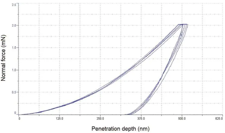
master structure. This structure consists of an array of five solid microneedles, which are attached to a solid rectangular substrate. (a) Top view of the microneedle array master structure. (b) Isometric view of the microneedle array master structure. (c) Front view of the microneedle array master structure. (d) Left-side view of the microneedle array master structure. ...64 Figure 4.3: Force–displacement data from nanoindentation of Gantrez® AN 169 BF
material. ...68 Figure 4.4: Fourier transform infrared spectrum for Gantrez® AN 169 BF material. ...69 Figure 4.5: Scanning electron micrographs of Gantrez® AN 169 BF microneedles within a
v mask micro-stereolithography-micromolding. (a) Scanning electron micrograph of three Gantrez® AN 169 BF microneedles. (b) Scanning electron micrograph of an individual Gantrez® AN 169 BF polymer microneedle. (c) Scanning electron micrograph of the tip of an individual Gantrez® AN 169 BF polymer microneedle. ...70 Figure 4.6: Agar diffusion assay results for the Gantrez® AN 169 BF microneedle arrays. The
microneedle arrays were evaluated using (a) B. subtilis, (b) C. albicans, (c) E. faecalis, (d)
E. coli, (e) P. aeruginosa and ( f ) S. aureus. The circles indicate the locations of the dissolved polymer. ...72 Figure 5.1: Schematic of microneedle array master structure design. a) Isometric view of
the microneedle array master structure design. b) Top view of the microneedle array master structure design. c) Front view of the microneedle array master structure design. d) Right side view of the microneedle array master structure design. ...86 Figure 5.2: Schematic showing fabrication of the microneedle array using a combination of
dynamic mask microstereolithography and micromolding. (a) The microneedle array master structure was fabricated out of eShell 300 by means of dynamic mask microstereolithography and was sputter coated with gold palladium. (b) To form micromolds, polymethylmethacrylate jigs were fabricated with a laser cutter to form a vessel. The jig was composed of a solid piece of PMMA, which served as a basement, with two donut-shaped pieces of PMMA; these components were held together with clamps in order to form a liquid-tight seal. The assembled jig formed a vessel with a volume of approximately 5.3 mL. (c) The PMMA jig was clamped together and ~4 mL of uncured PDMS was poured into the jig. (d) The master structure was then attached to a PMMA rectangular prism using Loctite 404, a cyanoacrylate adhesive. The master array was subsequently lowered into the unpolymerized PDMS. (e) The PMMA rectangular prism, which held the master structure, was allowed to rest on the edges of the PMMA jig. This arrangement held the master array in place; the PDMS was allowed to cure overnight at ambient temperature. (f) After the PDMS was cured, the PMMA jig was disassembled; the master structure was removed from the PDMS micromold. (g) The newly fabricated micromold was then filled with Gantrez AN 169 BF gel. (h) Following the application of Gantrez AN 169 BF to the micromold, the construct was centrifuged at 3500 rpm for 15 min. The Gantrez AN 169 BF was subsequently left at ambient temperature to dry overnight within the micromold. After drying of the Gantrez AN 169 BF, the hardened material was removed from the mold with forceps; using this approach, the shape of the master structure was conserved in the Gantrez AN 169 BF microneedle array. ...89 Figure 5.3: Scanning electron micrographs of unmodified Gantrez® AN 169 BF
microneedles. a) Front view of an unmodified Gantrez® AN 169 BF microneedle array; the entire array of five microneedles on top of the rectangular prism-shaped substrate. b) Front view of a single unmodified Gantrez® AN 169 BF microneedle. c) Top view of a single unmodified Gantrez® AN 169 BF microneedle. ...91 Figure 5.4: Scanning electron micrographs of inkjet modified Gantrez® AN 169 BF
vi Figure 5.5: Agar plate after 48 hours of incubation. Clear zones are areas where yeast inoculum was prevented from growing due to the presence of amphotericin B, which diffused from inkjet-modified microneedle arrays. ...93 Figure 6.1: Ejection of droplets from the piezoelectric inkjet printer nozzles at a jetting
voltage of 32.0 V is illustrated in this optical micrograph; images were captured at 20 µs intervals using an ultrafast camera. a) Graticule showing the distance that an ejected droplet travels within the 20 µs interval. b) Ejection of a droplet composed of pure dimethyl sulfoxide. c) Ejection of a droplet composed of miconazole dissolved in dimethyl sulfoxide. ... 108 Figure 6.2: Scanning electron micrographs of miconazole-loaded Gantrez® AN 169 BF
microneedles. a) Front view of a miconazole-loaded Gantrez® AN 169 BF microneedle array, which shows the entire array of five microneedles above the rectangular prism-shaped substrate. b) Front view of a single miconazole-loaded Gantrez® AN 169 BF microneedle. ... 110 Figure 6.3: Fourier transform infrared spectra for miconazole-loaded Gantrez® AN 169 BF
(Gantrez® AN 169 BF + miconazole), Gantrez® AN 169 BF solid miconazole in powder form (miconazole power), and pure dimethyl sulfoxide. ... 111 Figure 6.4: Agar plating assay results for the miconazole-loaded Gantrez® AN 169 BF
microneedle array (miconazole), the unmodified Gantrez® AN 169 BF microneedle array (control), and the Gantrez® AN 169 BF microneedle array modified with six layers of dimethyl sulfoxide (DMSO) against Candida albicans. ... 112 Figure 7.1: Scanning electron micrographs of (a ,b) injection molded PGA microstructures;
(c, d) drawing lithography-modified PGA microneedles; (e) EDS probe locations (A – microneedle; B – bulk substrate) on an injection molded microstructure; (f) EDS probe locations (A – microneedle inkjet printing-modified zone; B – microneedle non-inkjet printing-modified zone; C – bulk substrate). ... 130 Figure 7.2: Optical micrographs of (a) a drawing lithography-modified PGA microneedle
array without inkjet modification (b) a drawing lithography-modified PGA microneedle array after inkjet printing of voriconazole. The inkjet modification is discernible in the upper half of the drawing lithography-modified microneedles. ... 132 Figure 7.3: FTIR spectrum of PGA modified with voriconazole using inkjet printing. ... 136 Figure 7.4: Optical micrograph of (a) porcine skin following application of a methylene
blue-coated microneedle array (arrows indicate puncture locations); (b) methylene blue-coated microneedle prior to skin testing; (c) methylene blue-coated microneedle following skin testing, with dissolution of the blue coating at the upper portion of the microneedle. ... 137 Figure 7.5: Agar plates of microbial cultures following 24-hour exposure to unmodified,
vehicle-modified, and voriconazole-modified PGA microneedle arrays (a) C. albicans (b)
vii array of microneedles at 20x magnification. Print coatings can be observed on the front and back of the microneedles following the inkjet deposition process. Scale bars for (a, b, d, e) are 200 µm. Scale bars for (c, f) are 1 mm. ... 154 Figure 8.2: Optical micrographs of methylene blue and ITZ-modified (with PMVE/MA,
DMSO, coconut oil, and benzyl alcohol) PGA microneedles before (a – front side, b – back side) and after (c – front side, d – back side) insertion into porcine skin. The insertion sites into porcine skin are noted with the arrows in (e). Scale bars for all images are 1 mm. ... 156 Figure 8.3: FTIR spectra overlay of inkjet deposited composite coating containing signals
from PGA, itraconazole, benzyl alcohol, coconut oil, PMVE/MA, and DMSO. Individual spectra for coconut oil and itraconazole are used for comparison purposes, with key signature peaks labeled (A – O). ... 158 Figure 8.4: Modified-disk diffusion assay with C. albicans examining (2) PMVE/MA in DMSO
with ITZ in benzyl alcohol and (4) PMVE/MA in DMSO with ITZ and coconut oil in benzyl alcohol. Zones of growth inhibition are noted surroundings microneedles of compositions (2 & 4). ... 163 Figure 9.1: CAD schematic of the microneedle design and custom lateral flow test holder. a)
Clockwise from upper left, there are front, left, top, and isometric views of the microneedle design. b) Insertion of the microneedle into the central chamber of the test strip holder following application of the microneedles to the fish. c) Section view of the custom test strip holder showing the (1) washed sample reservoir for the test strip, (2) the central chamber holding the microneedle array in place, (3) the inlet port for the sample diluent. d) The sample diluent is added to the port at site (3) where it runs through the channel to the (2) central chamber, washing the acquired sample from the microneedles into the reservoir at site (1). The lateral flow test strip is placed into the groove at site (1) and is wetted by the microneedle wash/diluent, beginning the screening test. ... 172 Figure 9.2: Micrographs of the microstereolithography fabricated microneedles (a – c),
showing (a) the front view of the microneedles with the trapezoidal cutouts, (b) top view of the thin pyramidal geometries of the microneedles and the staggered orientation, (c) angled view of the microneedle structures; scale bars are 2 mm. In (d) a microneedle is inserted into a fresh piece of tuna steak and after removal in (e), indentations of the hand-applied device can be noted in the tissue. An example of a positive test is shown in (f), with a lateral flow test strip in the sample chamber that has been allowed to develop after incubating in diluent that washed over a microneedle array that had sampled a piece of histamine-spiked fish. ... 177 Figure 9.3: Graph of the mean (± S.E.M.) of the Accuscan® reader test:control ratio data for
histamine-spiked fish samples acquired through the microneedle protocol and the manufacturer-described protocol. Color intensity ratios acquired from sampling protocols are compared. For comparisons marked with “*” there was no noted statistical difference between the microneedle sampling technique and the blending technique described by the manufacturer when looking at the difference of means 95% confidence intervals for n = 9 of each test type. ... 178 Figure 9.4: Graph of the mean (± S.E.M.) of the Accuscan® reader test:control ratio data for
viii compared. For comparison marked with “*” there was no noted statistical difference between the microneedle sampling technique and the blending technique described by the manufacturer when looking at the difference of means 95% confidence intervals for n = 5 of each test type. ... 180 Figure 9.5: Graph of the mean (± S.E.M.) of the Accuscan® reader test:control ratio data for
1 Chapter 1 Introduction
This thesis describes the advances in microscale processing of materials utilized in applications for drug delivery and sampling of fluid for a biosensing application. Microneedle fabrication techniques and applications are the main crux of the thesis, with inkjet printing as a surface modification method utilized extensively to apply drug coatings to the microneedles. Much of the focus is placed on the deposition of antifungal drugs onto the surfaces of these microneedles as a means of transdermal delivery for superficial fungal infections.
2 Microneedle Background
Microneedles are small-scale, needle-like projections (typically less than 1 mm in length) that are used to physically penetrate the outermost layer of skin (stratum corneum) that serves as a major barrier to transdermal drug diffusion. The stratum corneum is composed of corneocytes in a lipid matrix, which serves as a transdermal drug diffusion barrier. The microneedles help to deliver therapeutic agents and vaccines through the skin and serve as a substitute to more traditional drug delivery mechanisms. For instance, microneedles are being investigated as an alternative to hypodermic needle delivery of drugs and vaccines. Although hypodermic needles are commonly used for subcutaneous and intravenous drug delivery, there are a number of problems associated with this method. For instance, needles are sometimes associated with patient fear with regard to needle size and the potential for pain, which can cause a lack of patient compliance with treatment regimens.[1,2] Additionally, use of hypodermic needles necessitates application by
trained personnel for safety and effectiveness.[2] Oral drug delivery is one of the most
desirable forms of administration of therapeutic agents due to its ease. However, first-pass metabolism by the liver and degradation of the therapeutic agent as it passes through the gastrointestinal tract limits efficacy and bioavailability.[3] Microneedles, however, serve as a
means to circumvent some of the disadvantages with oral and hypodermic needle delivery problems. Their small-scale limits pain sensation relative to needles, they can be fabricated in patch forms for administration without extensive training, and the transdermal delivery mechanism avoids drug degradation that results from first-pass metabolism and exposure to the gastrointestinal tract.[4]
3 Solid microneedles – Made of a variety of materials, including polymers, metals,
silicon, or ceramics that are coated with a therapeutic agent
Dissolving microneedles – Composed of water-soluble or biodegradable polymers or sugars, with a drug loaded within the microneedle or on the surface. Dissolution of the microneedle following skin insertion facilitates drug delivery.
Solid microneedles coupled with a transdermal patch – The skin is scraped or porated with a solid microneedle array, after which a topical transdermal patch or drug reservoir is applied at the penetration site, facilitating diffusion through the
stratum corneum.
Hollow microneedles – Microscale versions of a hypodermic needle, with a bore running through their structure, facilitating transit of a drug solution from a reservoir into the skin.
4 Dynamic Mask Microstereolithography
Dynamic mask microstereolithography uses the concept of digital light processing (DLP), or lamp and mirror-based microstereolithography. In this technique a lamp is utilized to project an image onto a photopolymerizable resin vat in order to produce a layer-by-layer build of a three-dimensional structure. Ultraviolet light or visible light sources are utilized, depending on the photoinitiator in the resin that is being cured. A schematic for this DLP technology setup is illustrated in Figure 1.1.[5] The lamp light is passed onto a
Digital Mirror Device (DMD), through a focusing lens, and onto a 45˚ mirrored surface before interacting with the resin. Thousands of individually addressable micro-scale mirrors make up the DMD. These mirrors are turned “on” or “off” in a digital manner, based on the 3D model input file guiding the structure build. This “dynamic mask” allows the light
5 above the 45˚ mirror. The layer-by-layer build is completed as each voxel of light exposed to the resin polymerizes the material, adhering the structure onto the build platform or the previously polymerized layer. The resolution of these systems varies by the material that is used during the photopolymerization, as the opacity of the material dictates the light diffusion of the voxel projected into the resin vat. Generally, x-y resolution is in the 25-50 µm range, with z-axis resolution varying from 15 µm to 100 µm. A number of different medically-related structures have been fabricated using this technique, including microneedle arrays. For instance, polymer microneedles for antimicrobial agent delivery,[6]
master structures for soft lithography micromolding applications,[7] and hollow
microneedles for biosensing applications[8] have all been fabricated with this technique.
Two-photon Polymerization
Two-photon polymerization (2PP) is a technique that uses a laser-guided trace to photocure a resin material. It is another stereolithography process, although it uses pulsed laser light as opposed to the DLP/microstereolithography lamp and build-platform approach described earlier. The basis for 2PP fabrication is the concept of two-photon absorption. In 2PP, femtosecond pulses of focused laser light are targeted into a photocurable resin in order to initiate a photoinitiated polymerization reaction. A nonlinear reaction occurs during these extremely short pulses of light, allowing the two photon absorption to be localized within the focal volume (voxel) of the laser light, resulting in localized polymerization reactions.[9] Since many photocurable resins can be crosslinked
6 emission of a photon from the fluorophore of the photoinitiator, and causing the polymerization reaction.[10] By tuning the excitation and emission wavelengths of the
photointiator with the laser parameters, polymerization can take place at the localized focal spot of the laser, but nowhere else within the resin. Additionally, since there is nonlinearity in the absorption event and the intensity needed for a polymerization reaction to initiate, the voxel that is polymerized can actually be smaller than the wavelength of light used to create the reaction. As a result, high resolution can be achieved with this technique, with reports of resolution as low as 100 nm.[11]
A typical setup for this type of fabrication technique is shown in Figure 1.2. A pulsed laser with 100 femtosecond pulse length, wavelength of λ = 800 nm, and high repetition rates (e.g., 80 MHz) is often utilized.[9] The pulsed laser light travels through a series of
optics and is focused into the sample resin using a high numerical aperture microscope lens. The sample is immobilized onto a moveable stage, which can raster back-and-forth according to the desired polymerization pattern, as the laser beam path polymerizes the desired geometry. Acrylic materials, organically modified ceramics, and epoxies may be
7 polymerized using this technique.[11,12] A number of biomedically relevant structures have
been fabricated with 2PP. For instance, tissue engineering scaffolds for cell seeding may have been fabricated using this technique.[13-16] Additionally, microneedles have been
fabricated using this technique, which of particular interest in this work.[17,18]
Injection Molding/Drawing Lithography
Injection molding is another method that has been investigated for fabrication of microneedle arrays.[19-22] In this process, machined or etched molds are utilized for the
pressurized injections of molten thermoplastics, which conform to the shape of the mold, are cooled, and then ejected following part fabrication. Microneedle arrays have been prepared in this manner from materials such as poly(lactic acid), poly(glycolic acid), cyclic olefin copolymer.[19-22] Use of a thermoplastic material allows the heat-based manipulation
of the material shapes. Drawing lithography is another approach that takes advantage of thermoplastic material properties. In this process, the transitions between the glass transition and melting temperatures of a thermoplastic material are controlled, while the material is drawn between two surfaces, thinning the structure and forming a sharpened point. Drawing lithography has also been utilized as a microneedle fabrication technique, drawing the material into tapered high aspect ratio structures.[23-25] We have investigated
the use of a combination of these two techniques, wherein injection molded microneedle structures are sharpened by a drawing lithography process to improve the aspect ratio and tip radii of the microneedles.[26]
Inkjet Printing
8 coating solution, removed at a controlled rate, and dried. While dip-coating methods have been utilized successfully in the past,[27-33] there are concerns over the consistency of the
thickness of the coatings and potential for contamination of the substrates. Furthermore, it is noted that improvements in microneedle dosing uniformity, minimization of expensive pharmacologic material waste, limiting spread of the coating onto the microneedle substrates, and the ability to scale the manufacturing process are important for surface coating applications on microneedle arrays. Inkjet printing is being investigated as a means of accurately applying drug coatings to microneedles due to some of these concerns.[28,33]
Inkjet printing has been utilized previously as an effective means of depositing pharmaceutical agents. For instance, Scoutaris et al. examined the inkjet deposition of mixtures of felodipine and polyvinyl pyrrolidone (PVP).[34] There was noted homogeneity in
the micro-spots of the patterned PVP-drug mixtures and drug release could be controlled by varying the drug loading percentage within ink. Acetaminophen, theophylline, and caffeine were deposited onto paper and polyethylene terephthalate (PET) substrates with a Dimatix DMP-2800 inkjet printer in another study.[35] This work looked into the ability to accurately
10 References
1. Y., Nir, A., Paz, E., Sabo, et al.Am. J. Trop. Med. Hyg. 2003, 68, 341-344. 2. E.L., Giudice, J.D., Campbell. Adv. Drug. Deliv. Rev. 2006, 58, 68-89.
3. S., Haeberle, D., Hradetzky, A., Schumacher, et al. IFMBE Proc. 2009, 25, 359-362. 4. Y.C., Kim, J.H., Park, M.R. Prausnitz, Adv. Drug Deliver. Rev. 2012, 64, 1547-1568. 5. S.J., Leigh, C.P., Purssell, J., Bowen, et al. Sensor. Actuat. A-Phys. 2011, 168, 66-71. 6. S.D., Gittard, P.R., Miller, C., Jin, et al. JOM. 2011a, 63, 59-68.
7. R.D., Boehm, P.R., Miller, W.A., Schell, et al. J.O.M. 2013, 65, 525-533.
8. P.R., Miller, S.D., Gittard, T.L., Edwards, et al. Biomicrofluidics. 2011, 5, 013415.
9. M.T., Raimondi, S.M., Eaton, M.M., Nava, et al. J. Appl. Biomater. Function Mater. 2012, 10,
56-66.
10.A., Waldbaur, H., Rapp, K., Länge, et al. Anal. Methods. 2011, 3, 2681-2716. 11.M., Farsari, M., Vamvakaki, B.N. Chichkov, J. Opt. 2010, 12, 124001.
12.M., Farsari and B.N. Chichkov. Nat. Photonics. 2009, 3, 450-452.
13.A., Ovsianikov, A., Ostendorf, B.N. Chichkov, Appl. Surf. Sci. 2007a, 253, 6599-6602. 14.A., Ovsianikov, S., Schlie, A., Ngezahayo, et al. J. Tissue Eng. Regen. Med. 2007b, 1,
443-449.
15.A., Ovsianikov, M., Gruene, M., Pflaum, et al. Biofabrication. 2010, 2, 014104. 16.A., Koroleva, S., Gittard, S., Schlie, et al. Biofabrication. 2012, 4, 015001.
17.A., Doraiswamy, A., Ovsianikov, S.D., Gittard, et al. J. Nanosci. Nanotechnol. 2010, 10,
6305-6312.
18.S.D., Gittard, A., Nguyen, K., Obata, et al. Biomed. Opt. Express. 2011b, 2, 3167-3178. 19.J.-H., Park, M.G., Allen, M.R. Prausnitz, J. Control. Release. 2005, 104, 51-66.
20.J.M., Lippmann, A.P. Pisano, Proc. IEEE. Micr. Elect. 2006, 19, 262-265.
11 24.K., Lee, J.D., Kim, C.Y., Lee, et al. Biomaterials. 2011b, 32, 7705-7710.
25.K., Lee, H., Jung. Biomaterials. 2012, 33, 7309-7326.
26.R.D., Boehm, J., Daniels, S., Stafslien, et al.Biointerphases. 2015, 10, 011004, DOI:10.1116/1.4913378.
27.Y.B., Schuetz, A., Naik, R.H., Guy, et al.Expert. Opin. Drug. Del. 2005, 2, 533. 28.H.S., Gill, M.R. Prausnitz, J. Control. Release. 2007a, 117, 227.
29.H.S., Gill, M.R. Prausnitz, Pharm. Res. 2007b, 24, 1369.
30.M., Cormier, B., Johnson, M., Ameri, et al.J. Control. Release. 2004, 97, 503. 31.J.A., Matriano, M., Cormier, J., Johnson, et al. Pharm. Res. 2002, 19, 63. 32.G., Widera, J., Johnson, L., Kim, et al. Vaccine. 2006, 24, 1653.
33.X., Chen, H.J., Corbett, S.R., Yukiko, et al. Adv. Funct. Mater. 2011, 21, 464.
34.N., Scoutaris, M.R., Alexander, P.R., Gellert, et al.J. Control. Release. 2011, 156, 179-185. 35.N., Sandler, A., Määttänen, P., Ihalainen, et al. J. Pharm. Sci. 2011, 100, 3386-3395. 36.R.D., Boehm, P.R., Miller, S.L., Hayes, et al. AIP Adv. 2011, 1, 022139,
DOI:10.1063/1.3602461
12 Chapter 2Piezoelectric Inkjet Printing of Medical Adhesives and Sealants
Ryan D. Boehm1, Shaun D. Gittard1, Jacqueline M. H. Byrne1, Jonathan J. Wilker2,
Timothy M. Dunaway2, Rene Crombez3, Weidian Shen3, Yuan-Shin Lee4, Roger J. Narayan5
1. Joint Department of Biomedical Engineering, University of North Carolina and North Carolina State University, Raleigh, NC, 27695, USA
2. Department of Chemistry, Purdue University, West Lafayette, Indiana 47907-2084, USA 3. Surface Science and Nano-Tribology Laboratory, Eastern Michigan University, Ypsilanti,
MI 48197, USA
4. Edward P. Fitts Department of Industrial and Systems Engineering, North Carolina State University, Raleigh, NC, 27695, USA
The following is a complete article reprinted from JOM, Volume 62, Ryan D Boehm, Shaun D Gittard, Jacqueline M H Byrne, Jonathan J Wilker, Timothy M Dunaway, Rene Crombez, Weidian Shen, Yuan-Shin Lee, and Roger J Narayan. 56-60, Copyright 2010.
13 Abstract
14 Introduction
Inkjet printing is an additive process that involves direct fabrication of microscale patterns of materials from two-dimensional pixelated images. By rasterizing the X- and Y- coordinates of the pixelated image, microscale patterns of materials for electronic, medical, optical, and polymeric applications may be prepared.[1,2] The resolution of the pattern is
dependent on several parameters, including drop size, ink viscosity, surface tension, and printer head resolution.[3] Fluid drops deposited by inkjet printers can range in volume
from picoliters to microliters; drop size is dependent on the nozzle dimensions.
Several manufacturers, including Hewlett-Packard, have developed thermal inkjet printers for desktop printing applications.[4] In these devices, the printer head contains a
heater, a fluid chamber, a manifold, a restrictor, and a nozzle. In thermal inkjet printing, ink is heated using a resistive element to ~300 °C until a bubble forms, which forces a droplet out of the printer head.[5] Thermal inkjet printing mechanisms have been categorized based
on the plane of bubble formation with respect to droplet ejection. For example, bubble formation and drop ejection are in the same direction in roof shooting thermal inkjet printers. Bubble formation and drop ejection are in opposite directions in back shooting inkjet printers. In side shooting inkjet printers, drop ejection is perpendicular to bubble formation. It should be noted that the high temperatures associated with thermal inkjet printing may preclude processing of some temperature-sensitive materials, including some biological materials.
Syringe-solenoid inkjet printers are commonly used for dispensing fluids in large-scale applications; these devices consist of a microsolenoid valve as well as a syringe pump.[6] A variety of solenoid dispensers, including flow through, aspirate-dispense, and
15 pharmacologic agents. In this research summary, the use of piezoelectric inkjet printing for patterning medical adhesives and sealants, including a two-component polyethylene glycol hydrogel-based medical sealant, an n-butyl cyanoacrylate tissue adhesive, and a mussel adhesive protein biological adhesive, is described.
Piezoelectric Inkjet Printing
Piezoelectric inkjet printing is a non-contact, additive process for creating microscale patterns using a variety of materials. In piezoelectric inkjet printing, actuation of a piezoelectric transducer enables the release of droplets; this technique can be performed at a range of temperatures (including room temperature). The printer head contains a lead zirconate titanate transducer, manifolds, nozzles, chambers, and fluid inlet passages. When voltage is applied to the transducer, vibrations produce acoustic waves, which force ink through the nozzles.[7] The type of deformation mode for the transducer gives rise to several
printer head categories, including squeeze mode, bender mode, push mode, and shear mode.8 The cartridge in the Materials Deposition System (Dimatix Inc., Santa Clara, CA) is an
example of a bender mode printer head; in this device, actuation of the transducer occurs in the wafer plane. The cartridge contains patterned lead zirconate titanate attached to a silicon diaphragm.[7] Viscosity and surface tension are important properties for materials
16 variety of bioassays, including immunoassays on gold substrates, glucose oxidase sensors on silicon oxide substrates, enzyme-based sensors on paper substrates, and immunoassays on disposable nylon membranes.[10-13] In addition, Tavana et al. utilized piezoelectric inkjet
printing to deliver patterns of genetic material to mammalian cells.[14] Piezoelectric inkjet
printing has also been used to prepare patterns of viable cells; for example, Merrin et al. and Saunders et al. used piezoelectric inkjet printing to create patterns of viable microorganisms (e.g., Escherichia coli) and human cells (e.g., HT 1080 human fibroblast cells), respectively.[15,16] In addition, piezoelectric inkjet printing has been used to create
microfluidic jets for deformation of lipid membranes and formation of vesicles.[17]
Preparation of Medical Adhesives and Sealants
Medical sealants based on hydrophilic polymers known as hydrogels have recently been developed. Cross-linking of hydrogels involves covalent bond formation by means of chemical reactions, photopolymerization, or ionizing radiation. Coseal® (Baxter, Deerfield, IL) is a hydrogel medical sealant composed of the following: (a) two polyethylene glycol polymers, (b) a sodium phosphate-sodium carbonate solution, (c) a hydrogen chloride solution; these components form a hydrogel, which covalently interacts with synthetic biomaterials and tissue proteins.[18-21] Coseal® has been utilized in urinary, neurological,
and cardiovascular procedures; leak-free closures have been produced.[18-21] Coseal® has
demonstrated high internal cohesion and tissue adhesion; for example, it has been shown to withstand supraphysiologic pressures in a porcine model.[22] In addition, Coseal® does not
induce tissue inflammation and resorbs within thirty days after use.[19,23] Piezoelectric inkjet
17 Figure 2.1: Scanning electron micrographs of CoSeal® material inkjetted in circular pattern on Si (111) substrates. Microscale Patterning of Two-Component Biomedical Hydrogel, A Doraiswamy, R Crombez, WDA Shen, YS Lee, RJ Narayan, Journal of Adhesion, 86 (1): 62-71, 2010. Reprinted by permission of the publisher (Taylor & Francis Group, http://www.informaworld.com).
In Doraiswamy et al., a DMP-2800 piezoelectric inkjet printer (Fujifilm Dimatix, Santa Clara CA) and a 10 picoliter drop size cartridge were used to create patterns of Coseal®.[24] Polyethylene glycol was dissolved in the sodium carbonate-sodium phosphate
solution; this solution was subsequently moved to an inkjet cartridge (part I solution). Dilute hydrogen chloride solution (part II solution) was transferred into another cartridge. Cross-linking of the hydrogel was obtained by initially inkjet printing a pattern with part I solution and subsequently inkjet printing directly over this pattern with part II solution.[25]
Inkjet printing parameters, including voltage, frequency, and waveform pulse shape, were independently optimized for each solution. Scanning electron microscopy images of the hydrogel patterns were obtained using a S3200 system (Hitachi, Tokyo, Japan), which was equipped with a Robinson backscattered electron detector. Scanning electron microscopy images of an inkjet printed CoSeal® circular pattern on a silicon substrate are shown in Figure 2.1. 300-400 μm wide circular patterns were noted; some shrinkage of the inkjet printed polyethylene glycol hydrogel sealant was observed.
18 warping. For example, many microvascular surgical procedures require joining of vessels in an end-to-end manner as well as closing of small vessels.[26] Suturing provides a 90-95%
success rate; however, blood vessel endothelium (inner layer) damage associated with suturing has been linked with platelet aggregation, foreign body reaction, blood vessel distortion, and blood vessel wall ischemia. Lacerations of the vessel endothelium can lead to formation of strictures and failure of grafted tissue.[27] An alternative mechanism for tissue
joining involves the use of medical adhesives; these adhesives must provide adequate tensile strength for several weeks while wound healing and tissue growth processes take place. Studies at the Walter Reed Army Medical Center have demonstrated the efficacy of n-butyl cyanoacrylate in wound hemostasis, tissue joining, and blood vessel joining.[28-34]
Matsumoto et al. showed that n-butyl cyanoacrylate enables less blood loss, less complex surgeries, and shorter operating times than suturing.[31-34] Saba et al. used an in vivo canine
model to demonstrate that sutureless joining of blood vessels with n-butyl cyanoacrylate is an appropriate alternative to suture-based tissue joining.[35] Cyanoacrylate tissue adhesives
have also for embolization of arteriovenous malformations (AVM).[36,37] In addition,
cyanoacrylate tissue adhesives have been used for vascular anastomosis (vessel joining) in a porcine carotid artery model; Bastiaanse et al. suggest that cyanoacrylate adhesives may be suitable for use as an alternative to suturing in closed chest surgery as well as other procedures that necessitate limited surgical access.[37]
In Doraiswamy et al., the DMP-2800 piezoelectric inkjet printer was used to prepare microscale patterns of Vetbond® butyl cyanoacrylate tissue adhesive, which consists of n-butyl cyanoacrylate (>98%), blue dye, as well as hydroquinone.[38] The inkjet printed
19 Figure 2.2: Phase contrast optical micrograph of array of Vetbond™ n-butyl cyanoacrylate adhesive on a glass microscope slide.
contrast microscopy using an upright DMLB instrument (Olympus Inc., Center Valley, PA). In recent work, a microscale adhesive dot array patterns were prepared with a 1 picoliter drop size cartridge on a glass microscope slide (Figure 2.2). An array of ~35 µm diameter disk-shaped structures was obtained; these structures are approximately the same size as human cells (10-30 µm).[39] Good dot size uniformity and consistent dot spacing were
20 Figure 2.3: Primary amino acid sequence of Mefp-1, Mefp-3, and Mefp-5 mussel adhesion proteins. A, K, P, S, Y, T, G, N, R, W, E, L are the single letter notations for the amino acids alanine, lysine, proline, serine, tyrosine, threonine, glycine, asparagine, arginine, tryptophan, glutamic acid, and leucine, respectively. Reprinted from J.H. Waite, Adhesion a la moule, Integrative and Comparative Biology, ©2002, 42, 6, 1172-1180, by permission of The Society for Integrative and Comparative Biology.
tetrazolium salt (MTT) to a purple formazan dye by the mitochondrial succinnic dehydrogenase enzyme.[40] Viability of cells on Vetbond® tissue adhesive was significantly
lower than on control material (media). Previous work by Chen et al. indicated that cultured bovine corneal epithelial cells, keratinocytes, and corneal endothelial cells exhibited cytotoxicity when exposed to drops of n-butyl cyanoacrylate.[41] Leggat et al. and Toriuni et
al. suggest that degradation of cyanoacrylate into cyanoacetate and formaldehyde is a contributor to in vivo as well as in vitro toxicity.[42,43] Inkjet printing, micropipetting, and
other microscale patterning technologies may serve to increase reduce the amount of cyanoacrylate adhesive needed for a given surgical procedure and decrease toxicity.44 In
21 Figure 2.4: Optical micrographs of mussel adhesive protein solution inkjetted into microarray and line patterns. Reprinted from A Doraiswamy, TM Dunaway, JJ Wilker, RJ Narayan, Inkjet Printing of Bioadhesives, Journal of Biomedical Materials Research Part B-Applied Biomaterials, 89B (1): 28-35, 2009 by permission of the publisher.
at the site of application.
Mussel adhesive proteins are adhesives that are utilized by sedentary mussels (bivalve mollusks or clams) for attachment to ships, rocks, piers, and other underwater surfaces. Mytilus edulis, the blue mussel, is a commonly studied organism that is primarily found in the intertidal zone on the coastlines of North American and Europe. This organism produces a number of adhesive proteins, which include Mytilus edulis foot protein-1, Mytilus edulis foot protein-2, Mytilus edulis foot protein-3, Mytilus edulis foot protein-4, Mytilus edulis foot protein-5, and Mytilus edulis foot protein-6.[45-53] Mussel adhesive
proteins contain up to thirty mole percent of 3,4-dihydroxyphenyl-L-alanine (DOPA), which is formed by post-translational modification of the amino acid L- tyrosine. DOPA is suggested to play a key role in adhesion of the mussel plaque to environmental surfaces (Figure 2.3); adhesion is believed to occur as a result of covalent coupling, chelate-mediated crosslinking, and/or noncovalent interactions.[45-53]
22 Figure 2.5: Topography-flattened atomic force micrograph of inkjetted mussel adhesive protein, 1:1 Fe:DOPA, 10:1 Fe:DOPA, and 100:1 Fe:DOPA structures. Scale bar equals 10 m. Reprinted from A Doraiswamy, TM Dunaway, JJ Wilker, RJ Narayan, Inkjet Printing of Bioadhesives, Journal of Biomedical Materials Research Part B-Applied Biomaterials, 89B (1): 28-35, 2009 by permission of the publisher.
from mussel feet using a process previously proposed by Waite et al. with the exception that protein pellet extraction was performed with water rather than with acetic acid.[54] The
resulting solution consisted of approximately 80% Mytilus edulis foot protein-1 and approximately 20% Mytilus edulis foot protein-2; it contained a total DOPA concentration of 0.16 mM. The DMP-2800 piezoelectric inkjet printer was used to prepare 1 cm2 patterns of
23 over the mussel adhesive protein pattern; 1:1, 10:1, and 100:1 Fe:DOPA ratios were obtained in the resulting structures. Patterns of Vetbond® n-butyl cyanoacrylate (3M, St. Paul, MN), Nexaband® 2-octyl cyanoacrylate (Abbott Laboratories, North Chicago, IL), and Loctite® ethyl cyanoacrylate (Ted Pella, Redding, CA) were prepared for comparison purposes.
Inkjet printing of mussel adhesive protein solution with a 10 picoliter drop size cartridge enabled a pattern with a minimum feature size of 50 µm as well as lines with widths of ~60, ~90, ~180, and ~300 µm to be obtained (Figure 2.4). As the firing voltage was increased, a linear increase in the velocity of the mussel adhesive protein solution was observed. Figure 2.5 shows atomic force microscopy of mussel adhesive protein solution upon addition of FeCl3 solution. Patterns of mussel adhesive protein solution in the absence
of iron demonstrated some fibrous networks. Complex fiber networks were observed in the 10:1 Fe:DOPA pattern and the 1:1 Fe:DOPA pattern; islands of cross-linked material were observed in the 100:1 Fe:DOPA pattern. Ninan et al. have described adhesion of marine mussel extracts using several curing conditions; they showed that oxidants such as Cr6+,
Fe3+, and V5+ increased the strength of joints formed with mussel adhesive protein
solution.[55] Ninan et al. also indicated that moisture adversely affects the curing behavior of
mussel adhesive protein.[56] Lee et al. previously utilized atomic force microscopy to
demonstrate single DOPA residue-wet metal oxide surface interactions are of a reversible and noncovalent nature.[57]
24 Figure 2.6: Average strength of bioadhesives inkjetted on full thickness porcine skin. All samples were cured for 24 hours. The difference in strength was statistically significant for all except those indicated by “*”, “^”, and “#” (P<0.05). Bars indicate standard deviation of mean strength. Reprinted from A Doraiswamy, TM Dunaway, JJ Wilker, RJ Narayan, Inkjet Printing of Bioadhesives, Journal of Biomedical Materials Research Part B-Applied Biomaterials, 89B (1): 28-35, 2009 by permission of the publisher.
cyanoacrylate-based adhesives (Figure 2.6). Ink printed ethyl cyanoacrylate, n-butyl cyanoacrylate, and 2-octyl cyanoacrylate exhibited high adhesion strengths; however, Pinkerton et al., Hauptmann et al., and Hauptmann et al., and Leggat et al. have noted the toxicity of these materials.[58-60] No correlation between adhesion strength and Fe (III)
concentration could be obtained from the tensile testing data. The low adhesion strength of the 100:1 Fe:DOPA pattern was attributed to the high degree of cross-linking within this material; Monahan et al. suggest that dissimilar catecholate complexes are created at low Fe:DOPA ratios and high Fe:DOPA ratios.[61]
Conclusion
26 References
1. J.H. Song et al., Journal of Materials and Processing Technology. 2004, 155-156, 1286. 2. A.V. Lemmo et al., Current Opinion in Biotechnology. 1998, 9, 615.
3. T. Xu et al., Biomaterials. 2005, 26, 93.
4. P. Calvert, Chemistry of Materials. 2001, 13, 3299.
5. K.D. Bae et al., Microelectronic Engineering. 2005, 78-79, 158.
6. C. Haber, M. Boillat, and B. van der Schoot, Assay and Drug Development Technologies. 2005, 3, 203.
7. C. Menzel, NIP20: International Conference on Digital Printing Technologies, Salt Lake City, Utah, 2005.
8. J. Brünahl et al., Sensors and Actuators A: Physical. 2002, 101, 371. 9. J. Sumerel et al., Biotechnology Journal. 2006, 1, 976.
10.T.N. Stewart et al., Biotechnology Journal. 2009, 4, 206. 11.M.S. Hasenbank et al., Analytica Chimica Acta. 2008, 611, 80. 12.G. Arrabito et al., Langmuir. 2009, 25, 6312.
13.S.M. Hossain et al., Analytical Chemistry. 2009, 81, 5474. 14. H. Tavana et al., Nature Materials. 2009, 8, 736.
15.J. Merrin et al., PLoS One. 2007, 2, e663.
16.R. E. Saunders et al., Biomaterials. 2007, 29, 193. 17.J. C. Stachowiak et al., Lab Chip. 2009, 9, 2003.
18.S. Ramakumar et al., Journal of Endourology. 2002, 16, A21. 19.S. Ramakumar et al., Journal of Endourology. 2002, 16, 489.
20.A. Hill et al., Journal of Biomedical Materials Research Part B: Applied Biomaterials. 2001, 58, 308.
21.S.L. Bennett et al., Journal of Cardiac Surgery. 2003, 18, 494. 22.E. L. Park et al., Journal of Urology. 2004, 172, 2446.
27 24.A. Doraiswamy et al., Journal of Adhesion. 2010, 86, 62.
25.K.L. Franco et al., Advanced Therapy in Thoracic Surgery, 2nd ed. (Shelton, CT: People's Medical Publishing House, 2005), 52.
26.S.P. Chow, Microsurgery. 1983, 4, 5.
27.A.R. Green et al., British Journal of Plastic Surgery. 1985, 38, 435. 28.D.K. Ousterhout et al., J. Surgical Research. 1970, 10, 213.
29.S.N. Bhaskar et al., Oral Surgery, Oral Medicine, and Oral Pathology. 1966, 22, 526. 30.J.A. Collins et al., Surgery. 1969, 65, 260.
31.M.T. Matsumoto et al., Archives of Surgery. 1967, 94, 187. 32.T. Matsumoto et al., Archives of Surgery. 1967, 94, 858. 33.T. Matsumoto et al., Archives of Surgery. 1967, 94, 392. 34.T. Matsumoto et al., Archives of Surgery. 1967, 94, 388. 35.D. Saba et al., European Surgical Research. 2007, 39, 239. 36.G.J. Velat et al., Neurosurgery. 2008, 63, ONS75.
37.J. Bastiaanse et al., Annals of Thoracic Surgery. 2000, 70, 1384. 38.A. Doraiswamy et al., Journal of Adhesion. 2010, 86, 1.
39.T. Mosmann, Journal of Immunologic Methods. 1983, 65, 55.
40.A. Doraiswamy et al., Journal of Biomedical Materials Research B: Applied Biomaterials. 2009, 89, 28.
41.W. L. Chen et al., Cornea. 2007, 26, 1228.
42.P.A. Leggat et al., ANZ Journal of Surgery. 2007, 77, 209.
43.D.M. Toriumi et al., Otolaryngologic Clinics of North America. 1994, 27, 203. 44.I.F. Wessels et al., Ophthalmic Surgery. 1989, 20, 211.
45.J.H. Waite et al., Biochemistry. 1985, 24, 5010.
28 48.J.H. Waite, Integrative and Comparative Biology. 2002, 42, 1172.
49.M. Wiegemann, Aquatic Science. 2005, 67, 166.
50.S.W. Taylor et al., Inorganic Chemistry. 1996, 35, 7572. 51.J. Monahan et al., Chemical Communications. 2003, 14, 1672.
52.M.J. Sever et al., Angewandte Chemie International Edition. 2004, 43, 448. 53.J.H. Waite et al., Journal of Adhesion. 2005, 81, 297.
54.J. H. Waite, Methods in Enzymology. 1995, 258, 1. 55.L. Ninan et al., Acta Biomaterialia. 2007, 3, 687. 56.L. Ninan et al., Biomaterials. 2003, 24, 4091.
57.H. Lee et al., Proceedings of the National Academy of Sciences. 2006, 103, 12999. 58.M. Hauptmann et al., Journal of the National Cancer Institute. 2003, 95, 1615. 59.L.E. Pinkerton et al., Occupational and Environmental Medicine. 2004, 61, 193. 60.P.A. Leggat et al., ANZ Journal of Surgery. 2007, 77, 209.
29 Chapter 3Modification of Microneedles Using Inkjet Printing
R D Boehm,1 P R Miller,1 S L Hayes,1 N A Monteiro-Riviere,1,2 and R J Narayan1
1. Joint Department of Biomedical Engineering, University of North Carolina and North Carolina State University, Raleigh, NC 27695-7115, USA
2. Center for Chemical Toxicology Research and Pharmacokinetics, Department of Clinical Sciences, North Carolina State University, Raleigh, NC 27695, USA
The following is a complete article reprinted from AIP Advances, Volume 1, R D Boehm, P R Miller, S L Hayes, N A Monteiro-Riviere, and R J Narayan. 022139, Copyright 2011.
30 Abstract
31 Introduction
Microneedles are small-scale needle-shaped devices in which one dimension of the device is less than 500 µm in length. These devices are used to produce pores in the 15 µ m-thick stratum corneum. This superficial layer of skin contains nonviable keratinized cells bathed in lipids; it functions as a primary barrier to transport of pharmacologic agents.[1-3]
Microneedles are commonly used to deliver charged, polar, or large pharmacologic agents (e.g., nucleic acid-containing agents) since these agents cannot be delivered in enteral form due to first-pass metabolism and/or pH- driven degradation.[4-6] Gill et al. showed that
microneedles are associated with less pain than 26-gauge hypodermic needles; this result is attributed to the fact that microneedles have fewer interactions with Pacinian corpuscles, Meissner’s corpuscles, and nerve endings in the dermis than conventional hypodermic needles.[7] Due to the small dimensions of microneedle devices, tissue damage at the
injection site is also minimized; this feature is useful for treatment of diabetes and other chronic medical conditions that necessitate frequent injections.[8] Furthermore, no
specialized medical training is necessary for microneedle use. Common drug delivery mechanisms involving microneedle devices include: (a) coating solid microneedles with one or more pharmacologic agents and inserting the coated microneedles into the skin; (b) flowing a liquid that contains one or more pharmacologic agents through the bores of hollow microneedles; and (c) puncturing the skin with microneedles and subsequently delivering one or more pharmacologic agents at the microneedle site by means of a patch.[9]
Dip coating is commonly used to prepare coatings on microneedles and other structures with complex geometries.[10] In dip coating, microneedles are dipped and withdrawn from a
32 Use of coated solid microneedles has been investigated by several researchers. For example, Cormier et al. demonstrated delivery of desmopressin to a hairless guinea pig model by mean of a titanium microneedle array; in this study, the microneedles were coated with 24 or 40 wt.% desmopressin and 0.2 wt.% polysorbate using a partial immersion process.[11] They noted that the partial immersion process resulted in creation of
some contaminated microneedle arrays, in which the coating extended to the microneedle base. Although good microneedle-to-microneedle coating uniformity was noted, the distribution of the coating was not uniform throughout the microneedle structure. Matriano
et al. coated ovalbumin solution onto titanium microneedle arrays. Ovalbumin in the coating interacts with immune cells within the skin; high antibody titers were obtained in a hairless guinea pig model using these devices.[12] Subsequent work showed that coating
only the topmost 100 µm of the microneedle tips within a microneedle array instead of the entire microneedle array increased the delivery efficiency from 4-14% to 48%-58%.[13]
It should be noted that several limitations are associated with conventional solid microneedle coating mechanisms. For example, the total amount of pharmacologic agent loaded on the microneedle is constrained by the microneedle surface area.[9] Gill et al.
33 specialized procedure, which involved masking and micropositioning, for eliminating interactions between the microneedle substrate and the coating solution. More recently, Chen et al. increased coating solution viscosity with sodium alginate; they demonstrated nanopatch-based delivery of ovalbumin protein and DNA using this approach. It should be noted that surface tension-related processes may serve to spread the microneedle coating to portions of the microneedle device (e.g., the microneedle substrate) where it is not needed.[15]
Gill et al. noted that increasing microneedle-to-microneedle dosage uniformity and minimizing waste of expensive pharmacologic agents are important considerations in the development of a microneedle coating process.[10] Chen et al. and Gill et al. described several
attributes of an ideal microneedle coating process; these include: (a) minimizing deposition of the coating material on the microneedle substrate, (b) minimizing heating or pH changes for the coating material, and (c) maximizing adhesion between the coating material and the microneedle material.[10,15] Chen et al. also noted that an ideal microneedle coating approach
should be suitable for scalable, industrial-scale processing.[15]
Inkjet printing may serve as an alternative approach for modifying the surfaces of microneedles. Inkjet printing is a non-contact process that has been used for dispensing picoliter volumes of biologically-relevant materials, including proteins and nucleic acids, in a drop-on-demand manner.[16-18] Kim et al. described inkjet printing as a “dosing robot” that
generates microscale patterns with arbitrary geometries.[19] Furthermore, coatings can be
deposited at room temperature on a wide variety of materials, including temperature-sensitive polymers and fabrics.[20] Abe et al. and Allain et al. noted that piezoelectric inkjet
printing is associated with low contamination rates and high reproducibility rates, respectively.[21,22] In addition, Dzik et al. noted that inkjet printing is associated with low cost
and low rates of material waste.[23] They also showed that materials can successfully be
34 demonstrated; for example, Lin et al. described inkjet processing rates as high as 10-2 m/s.[24] Cerna et al. noted that inkjet printing is more efficient process for creating coatings
than dip coating.[16] Mosiadz et al. noted that dip coating suffers from coating-to-coating
nonuniformity; inkjet printing provides greater control over coating amount.[25] In
piezoelectric inkjet printing, a container containing a dispersion or solution is surrounded by a piezoelectric actuator.[26] In this study, the container includes a silicon diaphragm, which
is attached to patterned lead zirconate titanate transducer. Voltage pulses lead to sub-micrometer scale contraction and expansion of the transducer; the pressure wave associated with this motion leads to droplet release from a nozzle. The droplet size is related to the nozzle dimensions. Deformation of the piezoelectric actuator is associated with bend, push, squeeze, or shear motions.[27] The cartridge used in this study contains a
bender mode printer head; transducer actuation takes place in the wafer plane. Increases in the applied voltage are associated with in- creases in droplet impact force, velocity, and mass. Unlike thermal inkjet printing, piezoelectric inkjet printing does not involve heating of the dispersion or solution. Piezoelectric inkjet printing also provides greater control over generation of the pressure pulse and ejection of the droplet than thermal inkjet printing.
A variety of materials, including glass, silicon, metals (e.g., nickel), metal alloys (e.g., stainless steel), non-biodegradable polymers (e.g., acrylate-based polymers) and biodegradable polymers (e.g., polylactic acid), have been used in microneedle fabrication.
[28-31] Using microneedles that are fabricated out of non-biodegradable materials is
problematic because broken microneedles may be retained within the skin. In this study, microneedles were fabricated out of a biodegradable acid anhydride copolymer (CAS 9011-16-9) containing alternating maleic anhydride and methyl vinyl ether groups, which is sold under the tradename Gantrez® AN-139.[32] Gantrez materials are soluble in organic solvents
![Figure 1.1: DLP schematic. a) Lamp light source b) Digital Mirror Device (DMD) c) Focusing lens d) 45˚ mirror e) Photoinitiated resin vat f) Build platform – Adapted from [5] – Fig](https://thumb-us.123doks.com/thumbv2/123dok_us/1575064.1193765/23.612.90.524.357.636/figure-schematic-digital-device-focusing-photoinitiated-platform-adapted.webp)
![Figure 1.2: “Scheme of the 2PP fabrication setup.” From [9] – Fig. 2, pg. 57.](https://thumb-us.123doks.com/thumbv2/123dok_us/1575064.1193765/25.612.128.500.277.496/figure-scheme-pp-fabrication-setup-fig-pg.webp)