The Improved Performance of the Brushless
DC Motor driven by using ANFIS Controller
C. Kala Krishna1, Dr. G. V. Marutheswar2
P.G. Student, Department of Electrical and Electronics Engineering, S V U College of Engineering, Tirupati, India1 Professor, Department of Electrical and Electronics Engineering, S V U College of Engineering, Tirupati, India2
ABSTRACT:This paper presents design and simulation of a fuzzy controller for achieving better performance of Brushless DC (BLDC) servomotor drive. The performance of fuzzy and PID controller-based BLDC servomotor drives is verified under different operating conditions such as change in reference speed , parameter variations, load disturbance, etc. BLDC servomotors are used in aerospace, instrumentation systems, space vehicles, electric vehicles, robotics, and industrial control applications. In such applications, conventional controllers like P, PI, and PID are being implemented with the BLDC servomotor drive control systems to achieve satisfactory transient and steady-state responses. However, the major problem occuring with the conventional PID controller is that the tuned gain parameters obtained from the BLDC servomotor drive control systems can not yield better transient andSteady-state responses under different operating conditions such as parameter variations, load disturbances, etc. The execution is contrasted with PID controller in order to demonstrate its ability to track the error and value of fuzzy controller in control applications .
KEYWORDS:Brushless DC (BLDC) motor, PID controller, Fuzzy logic controller, ANFIS controller.
.
I. INTRODUCTION
Brushless DC (BLDC) servomotor drives have been widely utilized as a part of air transportation, electric vehicles, and almost in every food and chemical industries. The conventional controllers like P, PI, and PID are being utilized for control applications more than couple of decades. It is key to develop the correct mathematical model, which is a method of simulating real-life situations with mathematical equations to forecast their future behavior for any system or reaction of the system for outlining these controllers but in pragmatic applications, systems are observed to be nonlinear and complex; so they are approximated as direct systems in order to get their mathematical model. The controller intended for such systems can just give satisfactory transient and steady-state responses reactions yet not ideal reactions. In the vast majority of the literature survey, it has been accepted that the system parameters never show signs of change during working conditions, however in pragmatic applications the mechanical load parameters, for example, dormancy and rubbing may change because of coupling or decoupling idleness components, and change in load. The phase resistance of the BLDC servomotor may like wise marginally change because of expansion of terminal resistance, change in winding resistance, and on-state resistance of the semiconductor changes because of progress in temperature during working conditions. It has been found that the proportion of no heap to full load contact is 1:15 and the change in snapshot of latency is up to 10–20 times due to coupling or decoupling latency components for regular automation, movement control, and positioning applications. The fundamental weakness of the ordinary controllers is that they can give better transient and consistant state reactions just when the system parameters for which they are planned stay unaltered. In a large portion of the reasonable systems, parameters of the system change during operation. The execution of these controllers and their reasonableness for wide range speed control of BLDC servomotor drive are explored under various working conditions, for instance, change in reference speed, parameter varieties, and load unsettling influence.
on the performance of the BLDC drives system is discussed in [2]. Several tuning methods for the PID controllers are described in [7]–[9]. The tuning method suggested is found to yield desired results, and hence this method is adopted for determining PID controller gain parameters. Design, implementation, and performance analysis of fuzzy logic controllers (FLCs) for various applications such as dc servomotor, BLDC motor, gas-turbine plant, servo systems are discussed in [4]. The genetic algorithm-based method for the determination of the PID controller parameters [8] for achieving improved performance is described. The robust adaptive and optimal control scheme to compensate for parametric and dynamic uncertainties in the BLDC motor drives is investigated in [5].The pulse width modulated (PWM) and digital controlschemes for the BLDC motor drives discussed in [1].Design and implementationof adaptive controllers,Outline and usage of adaptive controllers for enhancing the execution of dc motors and BLDC drives under various working conditions are examined in [2] , [3] , [5] .
II. MODELINGOFBLDCSERVOMOTORDRIVESYSTEM
The BLDC servomotor drive system consisting of BLDC servomotor and IGBT inverter is modeled based on the assumptions that all the stator phase windings have equal resistance per phase, constant self and mutual inductances; power semiconductor devices are ideal; iron losses are negligible. The proportionate circuit of the BLDC servomotor drive system is shown in Fig. 1. The line to line voltage conditions are communicated in system shape as
=
− 0
0 −
− 0 −
+
− − 0
0 − −
− 0 −
× +
− − −
Since the mutual inductance is negligible as compared to the self-inductance , therefore mentioned matrix equation can be rewritten as
=
− 0
0 −
− 0 −
+ − 0 0 − − 0 × + − − −
where L and M are self-inductance and mutual inductance per phase; R is the stator winding resistance per phase;
, and are the back EMFs of phases a, b, and c, separately; , , are the phase streams of phases a, b, and c, individually. The electromagnetic torque created by the motor can be expressed as
=( + + ) / = (3)
where = = = I,ωis the angular velocity in radians per second, and is the torque constant .Since this electromagnetic torque is utilized to overcome the opposing torques of inertia and load, it can also be written as
= + / + (4)
Where TLis the load torque, JMis the inertia, and is the friction constant of the BLDC servomotor .The load torque
can be expressed in terms of load inertia JLand friction BLcomponents as
= + (5)
The output power developed by the motor is
= (6)
= = = = (7)
Where Kbis back EMF constant, E is back EMF per phase, and ω is the angular velocity in radians per second.
The parameters of motor are phase resistance, phase inductance, also, inactivity and rubbing of BLDC servomotor and load. It is important to decide the parameters of both BLDC servo motor also, stack to plan routine controllers like P, PI, and PID controllers. The parameters that are probably going to fluctuate amid the working conditions are
the deceleration time of the speed reaction or the other way around. Another parameter, which is probably going to fluctuate during working conditions is phase resistance of the BLDC servomotor because of adding of terminal resistance, change in resistance of phase winding, and change in on-state resistance of IGBT changes because of slight progress in temperature. The change in phase resistance can likewise influence the speed reaction of the BLDC servomotor drive system. Blended mix of dormancy, contact, and phase resistance of the BLDC servomotor may prompt to increased overshoots that are undesirable in the majority of the control applications. Consequently, the BLDC servomotor drive system requires reasonable controllers as PID or Fuzzy controllers to accelerate the reaction ,minimize overshoot, and steady state mistake to get together the applications prerequisites. In this paper, PID and Fuzzy controller-based BLDC servomotor drive is simulated and their execution is simulated in various working conditions, for example, step change in reference speed, distinctive system parameters, and sudden load disturbance.
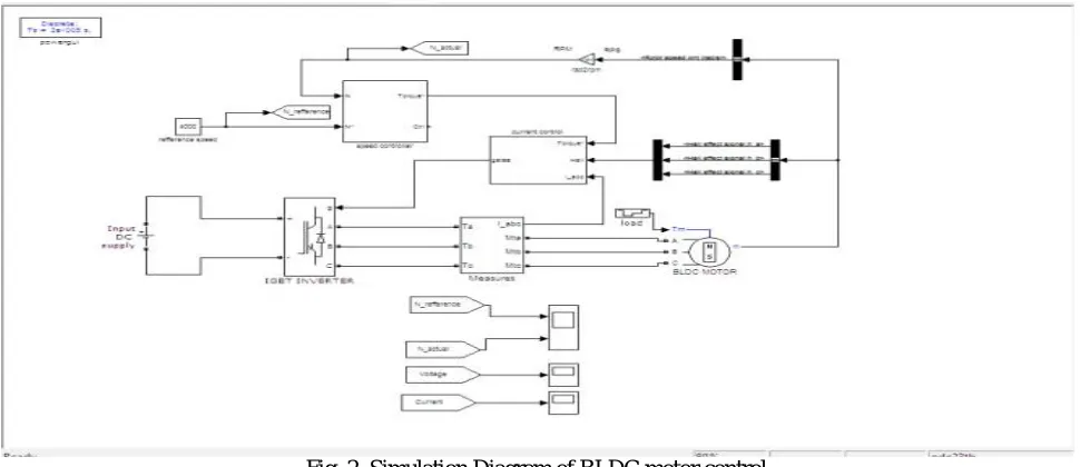
Fig. 2. Simulation Diagram of BLDC motor control III. DESIGN OF PIDCONTROLLER
Proportional Integral-Derivative controllers are broadly utilized as a part of modern control systems as they requires couple of parameters to be tuned in it. The PID controllers have the capability of eliminating steady-state errordue to integral action and can anticipate output changes due to derivative action when the system is subjected to a step reference input. The most prevalent PID tuning technique is the Ziegler–Nichols strategy, which depends exclusively on parameters got from the system step reaction. The piece chart of the trial set-up utilized for actualizing PID and fuzzy controller is shown in Fig. 2. The details of the BLDC servomotor are given in Appendix. The persistent control signal ( )of the PID controller is given by
( ) = ( ( ) + (1⁄ )∫ ( ) + ( )/ ) (8)
where, is the proportional gain, is the integral time constant, is the derivative time constant, and ( )is the error signal.
The corresponding discrete equation for the control signal can be written as
( ) = ( −1) + × ( ) + × ( −1) + × ( −2) (9)
Where ( −1) is the previous control output, ( −1) is the previous error, and ( −2)is the error preceding
( −1).
The constants , are given by
= − −2 ⁄ + ⁄2 (11)
= ⁄ (12)
= ⁄ (13)
= (14)
= 1/ (15)
Where f is the sampling frequency and T is the sampling rate. In this paper, a simple PID tuning method that is based on system step response is used to determine the controller gains. This method provides a systematic approach to adjust the proportional gain in order to minimize the overshoot. The PID controller gains determined are = 11, = 5, and = 0.1 for the BLDC servomotor drive system with effective inertia of motor and load = 350e-6 kg- , total friction coefficient of the motor and load B = 1e-4N.m/(rad/s) , resistance per phase ,R = 0.57 Ω, and inductance
per phase L = 1.5 mH. This system is tested under different operating conditions such as parameters variations, change in reference speed, and load disturbance.
IV.FUZZY LOGIC CONTROLLER
Fuzzy rationale is a type of numerous esteemed rationales in which reality estimations of variables might be any genuine number somewhere around 0 and 1. By differentiation, in Boolean rationale, reality estimations of variables may just be 0 or 1. Fuzzy rationale has been stretched out to handle the idea of halfway truth, where reality quality may extend between totally genuine and totally false. Besides, when etymological variables are utilized, these degrees might be overseen by particular capacities.
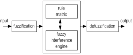
Normally fuzzy rationale control framework is made from four noteworthy components exhibited on Figure fuzzification interface, fuzzy induction motor, fuzzy principle grid and defuzzification interface. Every part alongside fundamental fuzzy rationale operations will be depicted in more detail below.
Fig. 3. Block Diagram of an Fuzzy Inference System
1. The fuzzy rationale investigation and control strategies shown in Figure 3 can be depicted as:
2. Receiving one or expansive number of estimations or other appraisal of conditions existing in some system that will be dissected or controlled.
3. Processing all inputs as indicated fuzzy "assuming then" standards, which can be communicated in basic dialect words, and consolidated with conventional non-fuzzy preparing.
V. ADAPTIVE NEURO FUZZY CONTROLLER
A fuzzy inference system and a back spread calculation. For a normal fuzzy deduction, the parameters in the participation capacities are generally controlled by experience or the experimentation technique. The adaptive neuro-fuzzy induction system can beat this burden through the way toward figuring out how to tailor the participation capacities to the info/output information keeping in mind the end goal to represent these sorts of varieties in the information values, as opposed to self-assertively picking parameters connected with a given enrollment work. This learning strategy works also to that of neural systems.
Adaptive Neural Fuzzy Inference System (ANFIS) is fuzzy Sugeno display put in the structure to encourage learning and adjustment strategy. Such system makes fuzzy rationale more orderly and less depending on master information. The target of ANFIS is to alter the parameters of a fuzzy system by applying a learning technique utilizing input–output preparing information. Essential design of ANFIS that has two sources of info x and y and one output f.
In matlab the principle contrast between fuzzy controller and adaptive neuro fuzzy controller is just we have in matlab two sorts fuzzy controllers one is mamdani and second one is Sugeno.
Mamdani is normal fuzzy controller in this we give information and output by utilizing a few suppositions yet as a part of Sugeno sort we give inputs just they consequently prepare outputs this is the fundamental distinction between two fuzzy controllers in matlab.
VI. IMPLEMENTATION AND PERFORMANCE ANALYSIS OF DIGITAL CONTROLLERS FOR BRUSHLESS DCMOTOR
DRIVES
SIMULATION RESULTS
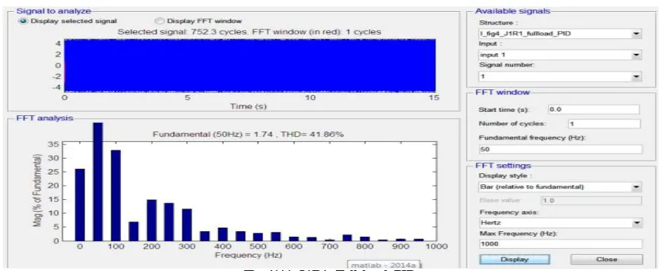
A. TOTALHORMONICDISTORTIONOFCURRENTWITHPIDCONTROLLER:
B. TOTAL HARMONIC DISTORTION OF CURRENT WITH FUZZYLOGICCONTROLLER:
Fig 4(B). J1R1 Full-load Fuzzy
C. TOTAL HORMONIC DISTORTION OF CURRENT WITH ANFIS CONTROLLER :
Fig 4(C). J1R1 Full-load ANFIS
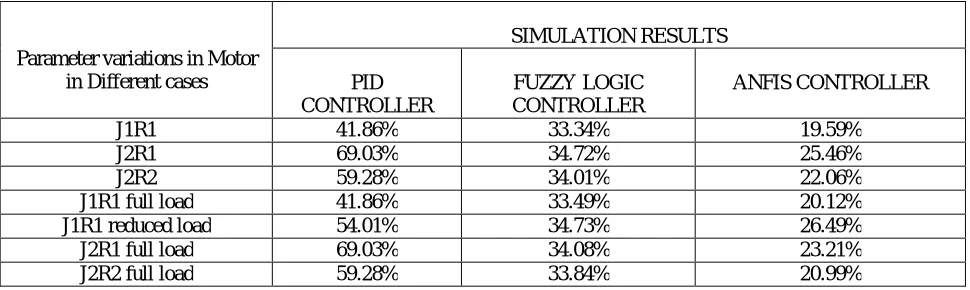
TABLE .1.TOTALHORMONICDISTORTIONOFCURRENTWITHPID,FUZZYANDANFISCONTROLLERS
Parameter variations in Motor in Different cases
SIMULATION RESULTS PID
CONTROLLER
FUZZY LOGIC CONTROLLER
VII. CONCLUSION
In this paper , we used PID and fuzzy control systems in existing. These are effectively simulated for the BLDC servomotor drive system. The impact of parameter variations departure fromthe execution of the BLDC servomotor drive system is investigated by simulation results .The performance simulated by using fuzzy logic controller is satisfactory when compared to PID controller. Compare to PID control of BLDC motor drive and fuzzy logic controller of BLDC motor drive under speed variation and parameter variations , the fuzzy logic controller drive have a good dynamic performance and reach steady state quickly. But in existing method by using PID and fuzzy logic controller , we got some harmonics in the current and voltage waveforms and some distortions in the output waveforms. So we have to reduce the total harmonic distortions in the voltage and current waveforms in the output waveforms. So , we used ANFIS controller here. By using ANFIS controllers we have reduced harmonics in the output of voltage and current waveforms .
SPECIFICATIONS OF BLDC MOTOR
REFERENCES
[1] R. Krishnan, Permanent Magnet Synchronous and Brushless DC Motor Drives: Theory, Operation, Performance, Modeling, Simulation, Analysis, and Design—Part 3, Permanent Magnet Brushless DCMachines and their Control. Boca Raton, FL: CRC Press, 2009, pp. 451–563. [2] P. Pillay and R. Krishnan, “Modeling, simulation, and analysis of permanent-magnet motor drives, part ii: The brushless dc motor drive,”
IEEE Trans. Ind. Appl., vol. 25, no. 2, pp. 274–279, Mar./Apr. 1989.
[3] R. Shanmugasundram, K. M. Zakariah, and N. Yadaiah, “Low-cost high performance brushless dc motor drive for speed control applications,” in Proc. IEEE Int. Conf. Adv. Recent Technol. Commun. Comput.,Kottayam, India, Oct. 27–28, 2009, pp. 456–460.
[4] R. Shanmugasundram, K. M. Zakariah, and N. Yadaiah, “Digital implementation of fuzzy logic controller for wide range speed control of brushless dc motor,” in Proc. IEEE Int. Conf. Veh. Electron. Safety, Pune, India, Nov. 10–12, 2009, pp. 119–124.
[5] A. K. Wallace and R. Spee, “The effects of motor parameters on the performance of brushless dc drives,” IEEE Trans. Power Electron., vol. 5, no. 1, pp. 2–8, Jan. 1990.
[6] V. M. Varatharaju, B. L. Mathur, and K. Udhyakumar, “Speed control of PMBLDC motor using MATLAB/Simulink and effects of load and inertia changes,” in Proc. 2nd Int. Conf.Mech. Electr. Technol., Sep. 10–12, 2010, pp. 543–548.
[7] J. G. Ziegler and N. B. Nichols, “Optimum settings for automatic controllers,” Trans. Amer. Soc. Mech. Eng., vol. 64, pp. 759–768, 1942. [8] J. C. Basilio and S. R. Matos, “Design of PI and PID controllers with transient performance specification,” IEEE Trans. Edu., vol. 45, no. 4,
pp. 364–370, Nov. 2002.
[9] Q.Wang ,T.Lee , H.Fung , Q.Bi , and Y.Zhang ,“PID tuning for improved performance,” IEEE Transactions on Control Systems Technology vol. 7 , no.4, pp. 457-465 , Jul. 1999 .