Evaluation of the Performance of Tie Rod and
Optimization Using FEA
Ganesh V. Gadge#1, Yugesh A. Kharche*2
M.E. Student, Department of Mechanical Engineering, VBKCOE Malkapur, India#1
Assistant Professor, Department of Mechanical Engineering, VBKCOE Malkapur, India*2
ABSTRACT : Tie rod is the part of steering system of an automobile. Tie rod is slender in structure and used to tie and sustains compressive and tensile loads. Fluctuating Forces and vibration due to bumps form automobile vehicle transmits to tie rod which may cause it to fail. The most percentage of forces on tie rod is compressive. Structural failure also takes place due to high severity of vibration and forces. Tie rods transmit force from the steering center link or the rack gear to the steering knuckle, causing the wheels to turn. A worn tie rod end, due to rubbing and wearing, can cause wandering, erratic steering and excessive tire wear. If tie rod replacement is necessary, a wheel alignment is also required because tie rod replacement disturbs the toe setting. Tie rods may fail in many different ways, and except for a slight increase in noise level and vibration, there is often no indication of difficulty until total failure occurs. Design of suspensions components in an automotive is very critical as they are constantly under varying loads. While designing the component, we must ensure the safety. Apart from design prospective it is important to focus on the weight and cost of an individual component. Here we are going to focus on the tie rod as a structural member, its functioning and performance. Here we are analyzing the existing Tie rod using FEA.
KEYWORDS: FEA; Modal FEA; Natural frequency; Forces coming on tie rod;
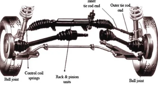
I. INTRODUCTION
Figure 1: Steering system of a passenger car
II. STATICS ANALYSIS OF EXISTING TIE ROD
Fig 2.1: Combined Boundary Condition Fig 2.2: Result for Deformation
Fig 2.3: Result for Von-mises stresses Table 1: Result for static Analysis
Sr. No.
Deformation (MM)
Von-mises stresses (MPa)
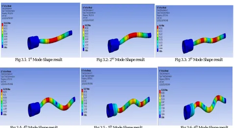
III. MODAL ANALYSIS OF TIE ROD FOR FINDING NATURAL FREQUENCIES
Fig 3.1: 1st Mode Shape result Fig 3.2: 2nd Mode Shape result Fig 3.3: 3rd Mode Shape result
Fig 3.4: 4th Mode Shape result Fig 3.5 : 5th Mode Shape result Fig 3.6: 6th Mode Shape result
IV. OPTIMIZATION ANALYSIS FOR TIE ROD AT DIFFERENT THICKNESSES (HOLLOW TIE ROD)
Solid Tie rod is over safe and further can be considering for Hollow shape (for weight reduction). For the same, dimension of hollow shaft is to be determined.
Considering various thicknesses and further Analysis of the same.Starting from di/do = 0.5
So do = 20.5 mm, hence di = 10.25 mm
Trial ID (mm) Thickness (mm)
1 8.5 6
2 9.0 5.75
3 9.50 5.5
4 10.0 5.25
5 10.25 5.125
6 10.50 5.0
7 11.0 4.75
8 11.50 4.5
9 12.0 4.25
Table 2: Tie rod at Different Thicknesses Table 3: Static Analysis Of Hallow Tie Rod Trial ID,
mm
Thickness, mm
Stress, MPa
Deformation, mm
Weight, kg
0 Solid -- 118.94 0.041988 1.96
1 8.5 6 144.86 0.052593 1.82
2 9.0 5.75 149.36 0.054226 1.803
3 9.50 5.5 154.44 0.0566062 1.785
4 10.0 5.25 160.18 0.058128 1.766
5 10.25 5.125 163.28 0.059246 1.756
6 10.50 5.0 166.6 0.06045 1.746
7 11.0 4.75 173.89 0.063084 1.725
V. OPTIMIZATION ANALYSIS FOR TIE ROD AT DIFFERENT MATERIALS
Steel- SM45C (Existing) The material properties are:
Young's Modulus 'E' 210 x 103MPa Poisson's ratio 0.3 Density 7860 kg/m3 Tensile strength, yield 343 MPa Ultimate tensile strength 569 MPa
Allowable Stress = Yield / FOS = 343/2.0 = 171.5 MPa
Fig5.1: Stress in Tie Rod (ID=10.5 mm) Fig 5.2: Deformation in Tie Rod (ID=10.5 mm)
Aluminium Alloy 6082 Cast Iron – FG 350
The material properties for AL 6082 are: The material properties are
:
Young's Modulus 'E' 72 x 103MPa Poisson's ratio 0.33
Density 2710 kg/m3 Tensile strength, yield 340 MPa Ultimate tensile strength 380 Mpa
Results for Aluminium Alloy:
Fig 5.3: Stress in Aluminium Tie Rod
Fig 5.4: Deformation in Aluminium Tie Rod
Young's Modulus 'E' 110 x 103MPa Poisson's ratio 0.29
Density 7200 kg/m3
Results for Cast Iron:
Fig 5.5: Stress in CI Tie Rod Fig 5.6: Deformation in CI Tie Rod
Material Stress, MPa Deformation, mm Weight, kg Allowable Stress, MPa
Steel SM45C 166.6 0.06045 1.746 171.5
Aluminium Alloy 6082 154.08 0.15908 0.6145 170.0
Cast Iron –
FG 350 174.12 0.11402 1.5993 175
Table 4: Results for various materials
-From the above result it can be seen that for weight condition Aluminium gives us better result without failure, hence can be used for alternative to existing material. Cost of material is less compare to Steel and Cast Iron.
-For case of Reliability and life, Steel is better (Weight on higher side).
-Cast Iron (CI ) is good in strength, higher in weight compare to Aluminium. Cost of CI is on higher side.
- Depending on requirement material can be selected. So we select Steel SM45C (Existing material) for further work because it gives better results as compare to other materials.
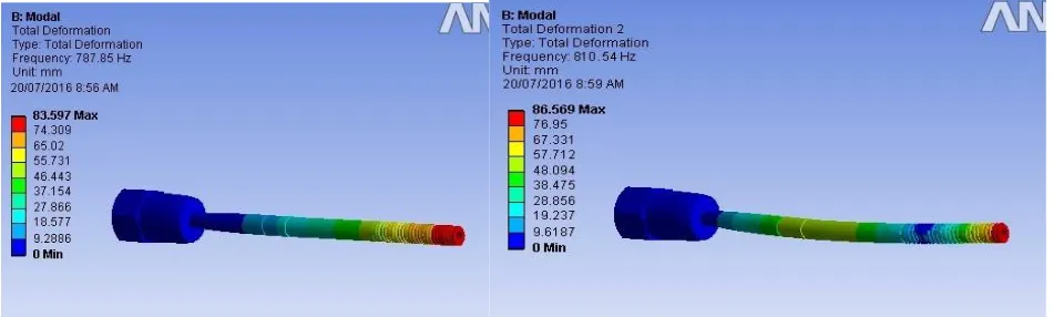
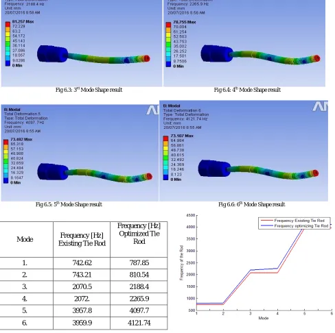
VI. MODAL ANALYSIS OF OPTIMIZED TIE ROD
Fig 6.3: 3rd Mode Shape result Fig 6.4: 4th Mode Shape result
Fig 6.5: 5th Mode Shape result Fig 6.6: 6th Mode Shape result
Table 6: Result for Modal Analysis (Existing and Optimized) Graph 1:Mode Shapes Vs Natural
From results of normal mode analysis, it is seen that the natural frequency of existing design is 742.62 Hz and proposed design is 787.85 Hz. So there is rise in natural frequency of proposed design. Further the second and onwards the frequencies of proposed design are increased compared to existing design. So overall the dynamic performance of tie rod is being improved.
Mode Frequency [Hz] Existing Tie Rod
Frequency [Hz] Optimized Tie
Rod
1. 742.62 787.85
2. 743.21 810.54
3. 2070.5 2188.4
4. 2072. 2265.9
5. 3957.8 4097.7
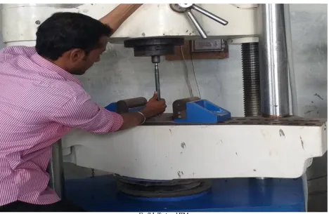
VII. VALIDATION
Fig 7.1: Test on UTM
Above figure shows the test set up of UTM. A compression test can be performed on UTM by keeping the Tie rod on base block and moving down the central grip to apply load. A compression testing machine shown in figure. it has two compression heads. The upper head moveable while the lower head is stationary. Load is applied from the top end of UTM vertically in Z-direction in pure axial direction. Initial load applied is 40N. The load is applied (its acts as compressive force) gradually to avoid any slippage of the rod during testing. Recorded change in length is tabulated. Test is carried out three times and average change in length is considered for finalized deformation.
Sr. No. Load (N)
Recorded change in length (mm) 1 40 0.01002 2 400 0.01435 3 800 0.02564 4 1200 0.03827 5 1500 0.03996 6 2000 0.041880
Table 7: Test Result of Load and Deformation of Existing tie rod Table 8:Test Result of Load and Deformation of Optimized tie rod
Sr. No. Load (N)
Condition ID, mm Material Deformation, mm
New Design 10.50 Steel- SM45C
(Hollow) 0.06010
Table 9: Results(Test results)
VIII. RESULT COMPARISON FOR EXISTING AND OPTIMIZED TIE RODS
Parameters Existing Tie Rod Optimized Tie Rod
Material Steel- SM45C (Solid)
Steel- SM45C (Hollow- ID – 10.50 mm)
Weight 1.96 kg 1.746 kg
% Change in Weight Hollow Tie rod is 12.25 % lighter than Steel
Stress 118.94 MPa 166.6 MPa
% Change in Stress Hollow tie rod has 28.60 % more Stress than Steel but its within allowable limit
Deformation 0.041988 mm 0.06045 mm
% Change in Deformation
Hollow tie rod has 30.54 % More deformation than Steel but it’s not big issue
IX. CONCLUSION
- Tie rod fillet radius plays important role in rod failure and should be carefully selected. -The results we got for Tie rod are showing good improvement compare to allowable stresses. - Tie rod with hollow ID- 10.50 mm shows safe results and is selected for further work.
- Hollow tie rod at 10.50 mm ID shows very less weight (12.25 %) compare to solid and hence finally suggested for Tie rod improvement for weight reduction application.
- Hollow tie rod at 10.50 mm ID shows high Stress (28.60 %) and deflection (30.54 %) values compare to steel but those are within limit while considering.
X. FUTURE SCOPE
- Dynamic Analysis can be done.
- Composite materials can be tested for less weight applications. - Effect of Vibrations can be consider
REFERENCES
1) Manik A. Patil, “FEA of Tie Rod of Steering System of Car” at IJAIEM, Volume 2, Issue 5, May 2013, ISSN 2319 – 4847.
2) Wei Duan “Failure analysis of threaded connections in large-scale steel tie rods” at Elsevier, Engineering Failure Analysis 18 (2011) 2008– 2018.
3) ShripadMungi and Prof. RavindraNavthar (2015),” Performance Optimization of Tie rod using FEA”IJERD, International Journal of
Engineering Research and Development, Volume 11, Issue 03 (March 2015), PP.27-33,e-ISSN: 2278-067X, p-ISSN: 2278-800X.
4) PradeepMahadevappa Chavan1 and M Patnaik (2014) “Performance evaluation of passenger car tie rod using numerical and theoretical
5) A.H. Falah “Failure investigation of a tie rod end of an automobile steering system” at Elsevier, Engineering Failure Analysis 14 (2007) 895– 902.
6) Soohyun Nam “Development of the light weight carbon composite tie bar” at Elsevier, Composite Structures 134 (2015) 124–131.
7) Prashant R. Vithalkar and R.R.Gawande (2015),”Study of analysis of bus passenger tie rod: a review” IJRET: International Journal of Research
in Engineering and Technology ,eISSN: 2319-1163,pISSN: 2321-7308.
8) Raghavendra K and Ravi K (2014), “Buckling analysis of tractor tie rod subjected to compressive load” International Journal of Mechanical
and Industrial Technology, Vol. 2, Issue 1, pp: (125-129).
9) IsmarAlagic,”FEM Simulation Of Tie-Rod Tensile Test”,10
th
International Research Conference,”Trends in the Development of Machinery and Associated Technology”TMT 2006, Barcelona - Lloret de Mar, Spain, September, 2006.
10) SaketBhishilkar,” Design and Simulation of 4 Wheel Steering”, International Journal of Engineering and Innovative Technology (IJEIT)
Volume 3, Issue 12, June 2014.
11) Ganesh B. Baraskar and Dr.V.S.Joshi (2016),”Performance evolution and optimization of tie rod in suspension system of car for a buckling
study using theoretical and experimental approach” IJSRD:International Journal for scientific research and
development,volume:3,issue:11,2016,issn(0nline):2321-0613.
12) Amanda M. Nauman,” Composite Tie Rod Research, Design and Testing For SAE Baja” (2015). Honors Research Projects. Paper 167.
13) Cristina Elena Popa,” Steering System and Suspension Design for 2005 Formula SAE-A Racer Car”, University of Southern Queensland,
October 2004.
14) K. Lohith,” Development Of Four Wheel Steering System For A Car”,SASTECH Journal, Volume 12, Issue 1, April 2013.
15) Raghavendra K and Ravi K (2014), “Buckling analysis of tractor tie rod subjected to compressive load” International Journal of Mechanical