19th International Conference on Structural Mechanics in Reactor Technology (SMiRT 19) Toronto, Canada, August 12-17, 2007
A general determination method of non-linear equivalent material
properties for perforated plates
Naoto KASAHARA, Nobuchika KAWASAKI and Takashi WAKAI
Advanced Nuclear System Research and Development Directorate, Japan Atomic Energy Agency,
Ibaraki, Japan
Hideki TAKASHO
Joyo Industries Ltd, Ibaraki, Japan
ABSTRACT
Tubesheet structures utilized in heat exchangers have complex perforated portions. For design analysis, axi-symmetric models with equivalent materials of perforated plate are conventionally adopted to simplify perforated portions. ASME Sec.Ⅲ Appendix A-8000 provides elastic constants for equivalent materials of perforated plate. In the case of elevated temperature reactors, elastic-plastic-creep deformation occurs in tubesheets. Therefore, design of these structures requires simplified models with non-linear equivalent materials for perforated plates. This study proposes a general determination method of non-linear equivalent material properties for perforated plates. Authors clarified that perforated plates have their own effective stress ratio (ESR). ESR is a function of geometry and is independent from their materials. ESR can determine non-linear equivalent material properties of perforated plates for any kind of constitutive equations of base metals. Applicability of this method was confirmed through example problems with typical constitutive equations and materials.
KEY WORDS: Perforated plate, Elastic-plastic, Creep, Inelastic analysis, Simplified analysis, Equivalent material properties, Effective stress ratio (ESR)
1. INTRODUCTION
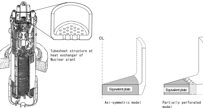
Tubesheet structures utilized in heat exchangers have complex perforated portions as in figure1. For realistic design analysis, simplified analysis models with equivalent solid plates are conventionally adopted. For design of light water reactors, Appendix A-8000 of ASME Boiler and Pressure Vessel Code Sec.Ⅲ(ASME 2004) provides elastic equivalent material properties to approximate perforated plates with equivalent solid plates. Equivalent material properties enable simplified analysis of perforated plates by axi-symmetric models and by partially perforated models (figure 1).
In the case of elevated temperature reactors such as fast breeder reactors, the yield stress of materials is reduced and creep deformation occurs during operations. Therefore, elastic-plastic-creep behaviors should be considered in structural design. To enable simplified analysis of their tubesheets, non-linear equivalent materials of perforated plates are necessary. For inelastic analysis, there exist many kinds of material properties and constitutive equations. Some non-linear equivalent material properties for perforated plates were proposed by Porowski et al.(1974),Igari et al.(1987), Kasahara et al.(1989), Gorden et al.(2002) and so on. On the other hand, design codes and standards require general design methods which are applicable for various kinds of material properties and constitutive equations. The purpose of this study is to develop a general determination method of non-linear equivalent material properties for perforated plates.
Tubesheet structure at heat exchanger of Nuclear plant
Axi-symmetric model Partially perforated
model Equivalent plate Equivalent plate
Figure 1 Simplified analysis model with equivalent plate for perforated plate
2. AVERAGE ELASTIC BEHAVIORS OF PERFORATED PLATES
A typical penetration pattern of tubesheets in heat exchangers is a triangular one. Geometry of this pattern can be determined by the ligament efficiency η =h/P (P: Pitch, h Ligament width) as in figure2. Average stiffness of triangular penetration plates depends on their ligament efficiencies. For equivalent solid plates with the above pattern, A-8000 provides equivalent Young’s modulus E* and Poisson’s ratio
ν
*
as functions of the ligament efficiency. To confirm effective elastic constants of A-8000, the authors have calculated average elastic behaviors of perforated plates by unit ligament models subjected to x-directional displacement (figure 3).304SS material properties at 550 and a plane stress model with unit thickness were assumed. Average stress
and strain of perforated plates are extracted by
x u
C
o
*
x
σ
* *,
yx
ε
ε
(
3 /2)
/ Fx
*
P x=
σ
,ε
*x=ux/(
P/2)
and /(
3 /2)
*P uy y =
ε
, (1)where, Fx is the reaction force, Uy is the associated displacement in y-direction. From average stress and strain, equivalent elastic constants are
* * *
/ x x
E =
σ
ε
,ν
*=ε
*y/ε
x*. (2)h/P=0.2 h/P=0.5 h/P=0.8
Ligament Efficiency
Stiffness of Perforated plate Small
Low
Large
High P
h
Figure 2 Perforated plates with triangular penetration Figure 3 Unit ligament model subjected to uni-axial pattern loading
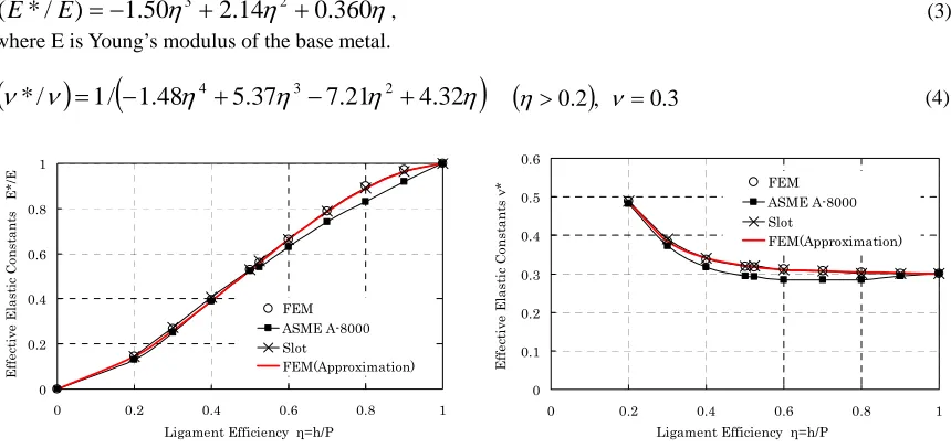
A-8000 and Slot et al.(1971) give equivalent elastic constants as in figure 4. F.E.calucurated results were over plotted on the same diagrams. F.E. results were very close to Slot’s solutions and can be approximated by the following equations (FEM Approximation).
η
η
η
2
.
14
0
.
360
50
.
1
)
/
*
(
E
E
=
−
3+
2+
, (3) where E is Young’s modulus of the base metal.(
ν
*
/
ν
)
=
1
/
(
−
1
.
48
η
4+
5
.
37
η
3−
7
.
21
η
2+
4
.
32
η
)
(
η
>0.2)
,ν
=0.3 (4)0 0.2 0.4 0.6 0.8 1
0 0.2 0.4 0.6 0.8 1
Ligament Efficiency η=h/P
Ef
fe
cti
ve
E
la
st
ic C
on
sta
n
ts
E*
/E
FEM ASME A-8000 Slot
FEM(Approximation)
0 0.1 0.2 0.3 0.4 0.5 0.6
0 0.2 0.4 0.6 0.8 1
Ligament Efficiency η=h/P
E
ff
ect
iv
e E
la
st
ic
C
on
st
an
ts
ν
* FEM
ASME A-8000 Slot
FEM(Approximation)
Figure 4 Equivalent elastic constants for perforated plates
3. AVERAGE INELASTIC BEHAVIORS OF PERFORATED PLATES
Equivalent inelastic properties are required to have compatibility with elastic ones and should be accurate under actual loading conditions. Structural analysis codes usually adopt Mises’s yield criterion, Mises’s equivalent stress, equivalent plastic (creep) strain and the associated flow rule. Therefore, Mises’s stress-strain curves are suitable to describe average inelastic behaviors of perforated plates.
Main loadings of tubesheets in heat exchanges are inner pressure and thermal stress at transient operations. Under the above conditions, average stress of perforated area becomes approximately equi-biaxial. So that, inelastic behaviors of perforated plates due to equi-biaxial loading were investigated with unit ligament models
(figure 5). A plane stress models with unit thickness were adopted. Average stress and strain in
x-direction can be extracted from forced displacement u
*
x
σ
*x
ε
x and reaction force Fx as(
/2 3)
/ Fx *
P x =
σ
, * /(
/2 (5) Pux
x =
ε
)
Taking the equi-biaxial loading and plane stress conditions into consideration,the Mises’s equivalent stress
and Mises’s equivalent plastic (creep) strain can be calculated from and according to
the following equations. *
eq
σ
*) (c eq p
ε
*x
σ
*x
ε
* *
x eq
σ
σ
= ,ε
*p(c)eq=
2
(
ε
x*−
ε
e*)
, (6)where * e
ε is the in-plane elastic strain. Under the plane stress condition, *
e
ε is given as
(
*)
* **
/
1 x E
e
ν
σ
ε
= − , (7)where
ν
* and E* are the equivalent Poisson’s ratio and the equivalent Young’s modulus given by equations (3) and (4).Introducing equation(7), equation(6) becomes
* *
x eq
σ
σ
= ,ε
*p(c)eq=
2
{
ε
x*−
(
1
−
ν
*)
σ
*x/
E
*}
, (8)Equation(8) can convert relationship obtained from equation (5) into relationship. It
is noted that
* *
x x
ε
σ
−
*) ( *
eq c p eq ε
σ −
(
*)
*/
1−ν E in equation(8) can be obtained directly from * * curve. x
x ε
σ −
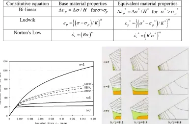
By using equation(8) and nonlinear finite element analysis of unit ligament models, Mises’s equivalent stress-strain curves for perforated plates with various kinds of materials and ligament efficiencies were calculated. Table 1 gives applied inelastic constitutive equations to describe material properties of base materials. For example, Ludwik equation was adopted to express a wide range of elastic-plastic properties which envelop cyclic stress-strain curves of 304SS from 500 to 600 (figure 6). Stress distribution in ligament varies according to both materials and ligament efficiencies as in figure 7.
C
o
C
o
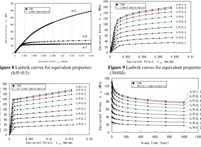
In figure 8, symbols show average Mises’s equivalent stress-strain relationships for perforated plates(h/P=0.5) calculated by finite element analysis of unit ligament models with material properties of figure 6. Solid lines are Ludwik approximation of FEM results by the least mean square method. Figure 9 shows equivalent stress-strain curves for various ligament efficiencies calculated from finite element models with the monotonic curve of 304SS at 550 described by the Ludwik curve and their approximations. Figure 10 is the similar diagram for bi-linear curves. Figure 11 shows average stress relaxation curves of perforated plates calculated by Norton’s equation of 304SS at 550 . Theses results clarified that equivalent material properties of perforated plates can be described by the same constitutive equations as the base metals (Table 1).
C
o
C
o
Figure 5 Unit ligament model subjected to equi-biaxial loading
Table 1 Inelastic constitutive equations
Constitutive equation Base material properties Equivalent material properties Bi-linear Δ
ε
p = Δσ
/H forσ σ
> p Δε
p*= Δσ
*/H* forσ
*>σ
p*Ludwik
{
(
)
}
/ n
p p K
ε = σ σ− *
{
(
* *)
*}
/ n
p p K
ε = σ −σ
Norton’s Low
( )
mc B
ε& = σ *
(
* *)
mc B
ε& = σ
0 200 400 600 800 1000 1200
0 0.002 0.004 0.006 0.008 0.01 0.012 0.014 0.016
Equivalent Strain εeq (mm/mm)
Equivalent
Stress σ
eq
(MPa)
n=3
n=5
n=7 500℃ 550℃ 600℃
Figure 6 Ludwik curves of base metal Figure 7 Mises’ stress distribution in unit ligaments
0 100 200 300 400 500 600 700
0 0.002 0.004 0.006 0.008 0.01 0.012 0.014 0.016
Equivalent Strain εeq (mm/mm)
Equ iv ale nt S tre ss σ eq ( MP a) n=3 n=5 n=7 ●:FEM -:Ludwik Approximation 0 20 40 60 80 100 120 140 160 180
0 0.002 0.004 0.006 0.008 0.01 Equivalent Strain εeq (mm/mm)
Equival ent Stress σ eq (MPa) h/P=0.9 h/P=0.8 h/P=0.7 h/P=0.6 h/P=0.5 h/P=0.4 h/P=0.3 h/P=0.2 h/P=1.0 ● : FEM
- : Ludwik Approximation
Figure 8 Ludwik curves for equivalent properties Figure 9 Ludwik curves for equivalent properties (h/P=0.5) (304SS)
0 20 40 60 80 100 120 140 160 180 200
0 0.005 0.01 0.015 0.02 Equivalent Strain εeq (mm/mm)
Equ iva le nt Str ess σ eq ( MP a ) ●:FEM
-:Bi-linear Approximation h/P=0.9
h/P=0.8 h/P=0.7 h/P=0.6 h/P=0.5 h/P=0.4 h/P=0.3 h/P=0.2 h/P=1.0 0 20 40 60 80 100 120 140
0 200 400 600 800 1000 1200
Creep time (hour)
Equ ival ent Str ess σ eq (MPa ) h/P=0.9 h/P=0.8 h/P=0.7 h/P=0.6 h/P=0.5 h/P=0.4 h/P=0.3 h/P=0.2 h/P=1.0
● : FEM
- : Norton's Approximation
Figure 10 Bi-linear curves for equivalent properties Figure 11 Norton curves for equivalent properties (304SS) (304SS)
4. EFFECTIVE STRESS RATIO (ESR) BETWEEN BASE METAL AND EQUIVALENT SOLID PLATES
Equivalent material properties described in Table 1 can be obtained from the least mean square approximation of Mises’s equivalent stress-strain curves calculated by FEM. From these results, the relation between base material properties and equivalent material properties were investigated. This led to the general characteristics of equivalent material properties among various constitutive equations: the powers of both Ludwik equation (n) and Norton’s law (m) were the same between base materials and equivalent materials, and the ratio of other properties between base materials and equivalent materials described in Table 2 has the common dependency to ligament efficiencies. Figure 12 shows that these ratios are independent from both powers of Ludwik equation and kinds of constitutive equations. It means that these ratios are functions of geometry only and are independent from constitutive equations. Furthermore, dimension of these properties described in Table 2 is the same as the stress. The above examination gives physical meaning to the ratio of properties between base materials and equivalent materials as effective stress ratio (ESR).
Trend of ESR to ligament efficiency can be obtained by average curve of figure 12. Approximated average curve from Fig.12 is solid line and its equation is given by
4 3 2
1.69
2.60
1.16
1.25
ESR
= −
η
+
η
−
η
+
η
,0
≤ ≤
η
1
. (9)Table 2 Ratio of properties between base materials and equivalent materials
Elastic Plastic Creep
ESR
γ
*γ
(*) *H
H
* p pσ
σ
*K
K
*B
B
(*)
γ
=
E
/(1
−
ν γ
),
*=
E
* /(1
−
ν
*)
0 0.2 0.4 0.6 0.8 1
0 0.2 0.4 0.6 0.8 1
Ligament efficiency η=h/P
Ef fec tiv e St re ss R at io (E SR )
K*/K(n3)
σp*/σp(n3)
K*/K(n5)
σp*/σp(n5)
K*/K(n7)
σp*/σp(n7)
Average Curve (ESR) 0
0.2 0.4 0.6 0.8 1
0 0.2 0.4 0.6 0.8
Ligament efficiency η=h/P
Effe ct iv e S tre ss R atio (E SR 1 ) Bi-linear H*/H Bi-linear σp*/σp Ludwik σp*/σp Ludwik K*/K Norton B/B* Elastic γ*/γ
Average Curve (ESR)
Figure 12 F.E. calculated ratio of properties between base materials and equivalent materials and their average curve (ESR)
5. APPLICABILITY OF THE DETERMINATION METHOD BY ESR
Non-linear equivalent material properties for perforated plates can be determined by using equation (9) and table 1. Figure 13 compares determined material curves by ESR with FEM results of figures 8,9,10,11. ESR sufficiently predicts equivalent materials.
0 100 200 300 400 500 600 700
0 0.002 0.004 0.006 0.008 0.01 0.012 0.014 0.016
Equivalent Strain εeq (mm/mm)
Equiva lent Stre ss σ eq (M Pa) n=3 n=5 n=7 ●:FEM
-:Ludwik with ESR
0 20 40 60 80 100 120 140 160 180
0 0.002 0.004 0.006 0.008 0.01 Equivalent Strain εeq (mm/mm)
Eq uiv ale nt Str ess σ eq ( MPa ) h/P=0.9 h/P=0.8 h/P=0.7 h/P=0.6 h/P=0.5 h/P=0.4 h/P=0.3 h/P=0.2 h/P=1.0 ● :FEM
- :Ludwik with ESR
0 20 40 60 80 100 120 140 160 180 200
0 0.005 0.01 0.015 0.02 Equivalent Strain εeq (mm/mm)
E qui val ent S tre ss σ eq ( MP
a) ●:FEM-: Bi-linear with ESR
h/P=0.9 h/P=0.8 h/P=0.7 h/P=0.6 h/P=0.5 h/P=0.4 h/P=0.3 h/P=0.2 h/P=1.0 0 20 40 60 80 100 120 140
0 200 400 600 800 1000 1200
Creep time (hour)
E
quivalent S
tress σ
eq
(MPa)
● :FEM - :Norton with ESR
h/P=0.9 h/P=0.8 h/P=0.7 h/P=0.6 h/P=0.5 h/P=0.4 h/P=0.3 h/P=0.2 h/P=1.0
Figure 13 Comparison of determined material curves by ESR with FEM
ESR can evaluate any other materials than figures 8,9,10,11. For example, equivalent elastic-plastic properties for Mod.9Cr-1Mo were determined with sufficient accuracy as in figure 14.
Furthermore, ESR is applicable to any other constitutive equations than table 1. Japanese design codes for FBRs (Iida, 1987) adopts Blackburn type equations to describe non-stationary creep strain. Blackburn type equivalent material properties for perforated plates can be determined by ESR as
(
1) (
2)
*
1 1 2 1
r t r t
c =C −e− +C −e− +ε&mt,
ε
&
m=
F
exp
{
−
Q
/
R
(
T
+
273
.
15
)
}
t
R−λ,r
1=
a
1t
R−b1,r
2=
a
2t
R−b2ε
(
)
2
* *
10 10 10
log C Rt a blog c log
ESR ESR
σ
α = + + ⎜⎜⎛
⎝ ⎠
σ ⎞
⎟⎟ (10)
Accuracy of equation (10) was confirmed by comparison with FEM results as in figure 15.
0 50 100 150 200 250 300 350 400
0 0.001 0.002 0.003 0.004 0.005 0.006 0.007 0.008 0.009 Equivalent Strain εeq (mm/mm)
Equivalent Stress σ
eq
(MPa)
h/P=1.0 h/P=0.9 h/P=0.8
h/P=0.7
h/P=0.6
h/P=0.5
h/P=0.4
h/P=0.3
h/P=0.2 ●:FEM
-:Ludwik with ESR
0 20 40 60 80 100 120 140
0 200 400 600 800 1000 1200 Creep time (hour)
Equ
iva
le
nt
St
res
s
σ
eq
(
MP
a)
h/P=1.0 h/P=0.9
h/P=0.8
h/P=0.7 h/P=0.6
h/P=0.5
h/P=0.4
h/P=0.3
h/P=0.2
●:FEM
-:Blackburn with ESR
Figure 14 Determined Elastic-plastic curve Figure 15 Determined Brackburn type creep by ESR (Mod.9Cr-1Mo) curves by ESR (304SS)
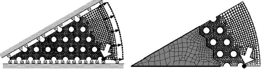
6. VALIDATION BY PERFORATED PLATE MODELS
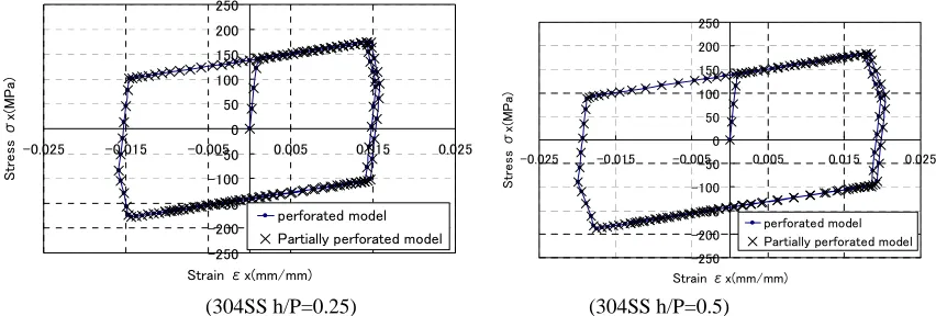
To validate total accuracy of simplified analysis models with equivalent material properties determined by ESR, they were applied to realistic design problems. Figure 16 are perforated plates subjected to cyclic radial displacement at the edge of rim. Their material is 304SS at 550 . Cyclic elastic-plastic-creep deformation occurs in the perforated plates. Two kinds of analysis models were applied and their results were compared. One is a full perforated plate model and the other is a partially perforated model with equivalent material properties. As constitutive equations for base material, bi-linear approximation and Norton’s law were adopted for elastic-plastic and creep calculation. Two Ligament efficiencies h/P=0.5 and h/P=0.25 were investigated. Both models exhibited the maximum stress at the edge of the outermost hole. Therefore, calculated elastic-plastic-creep curves were compared at this portion between perforated plate and partially perforated plate models. Both models predicted the quite similar results for h/P=0.5 and h/P=0.25 cases as in figure 17.
C
o
Figure 16 Perforated plate models subjected to cyclic loadings and partially perforated model with equivalent solid plate determined by ESR(304SS, h/P=0.5)
-250 -200 -150 -100 -50 0 50 100 150 200 250
-0.025 -0.015 -0.005 0.005 0.015 0.025
Strain εx(mm/mm)
S
tr
e
ss
σ
x(
M
P
a)
perforated model Partially perforated model
-250 -200 -150 -100 -50 0 50 100 150 200 250
-0.025 -0.015 -0.005 0.005 0.015 0.025
Strain εx(mm/mm)
Stre
ss
σx
(M
P
a)
perforated model Partially perforated model
(304SS h/P=0.25) (304SS h/P=0.5)
Figure 17 Comparison of calculated elastic-plastic-creep curves between perforated plate model and partially perforated plate model (Bi-linear Approximation + Norton’s Law)
7.CONCLUSIONS
For simplified inelastic analysis of perforated plates, the following equations were proposed to determine equivalent material properties for perforated plates.
・Equivalent elastic constants
η
η
η
2.14 0.36050 . 1 ) / *
( =− 3+ 2+
E E
(
ν
*/ν
)
=1/(
−1.48η
4+5.37η
3−7.21η
2+4.32η
)
,η
>
0
.
2
,
ν
=
0
.
3
・Effective stress ratio(ESR) to determine non-linear equivalent material properties
4 3 2
1.69
2.60
1.16
1.25
ESR
= −
η
+
η
−
η
+
η
,0
≤ ≤
η
1
Physical meaning of ESR is an effective stress ratio between perforated plates and equivalent solid plates. ESR is a function of geometry and is independent from constitutive equations. ESR can determine non-linear equivalent material properties for perforated plates from any kind of constitutive equations of base materials. Assumptions in ESR are Mises’s equivalent stress-strain relationship and equi-biaxial loadings.
REFERENCES
ASME (2004), Stresses in Perforated Flat Plates, ASME Boiler and Pressure Vessel Code Sec.III Appendix A-8000
Porowski,J.and O’Donell,W.,J. (1974), Effective plastic constants for perforated materials, ASME, J. of Pressure Vessel Technoligy, Vol.124, Issue 2, pp.201-206
Slot, T., O’Donell,W.,J. "Effective Elastic Constants for Thick Perforated Plates with Square and Triangular Penetration Patterns" , J.of Eng.for Industry , August , 1971 , PP1081/1101
Igari,T., Setoguchi,K., Matsumura,N. and Nomura,S. (1987), Experimental study on macroscopic creep behavior of perforated plates, SMiRT9, Vol.L, pp219/224
Kasahara,N, Iwata,K., Imazu, A., Horikiri, M. and Tokura,S.(1989), High temperature design methods for tubesheet structures with validation by thermal transient testing, SMiRT10, Vol.E, pp1/10
Gorden, J.L. Jones,D.P., Banas,D. and Hutula, D.N. (2002), A Collapse Surface for a Perforated Plate With an Equilateral Triangular Array of Penetrations, ASME, J. of Pressure Vessel Technoligy, Vol.124, Issue 2, pp.201-206
Iida,K., Asada,Y. and Okabayashi,K, (1987), Construction Codes for Prototype FBR MONJU, Nuclear Engineering and Design 98, pp283/288