Transactions of the 17th International Conference on
Structural Mechanics in Reactor Technology (SMiRT 17) Prague, Czech Republic, August 17 –22, 2003
Paper # F02-3
Adaptation of the Modern Approaches for Protection of Nuclear Power Plants
against the Effects of Postulated Pipe Ruptures to the Russian National Guides.
Problems and Experience.
Alexei Berkovsky1), Victor Kostarev1), John D. Stevenson2) 1) CKTI-Vibroseism, St. Petersburg, Russian Federation 2) J.D. Stevenson, Consulting Engineer, Cleveland, Ohio, USA ABSTRACT
Requirements for protection of Nuclear Power Plants against postulated ruptures of High-Energy Piping systems present practically in all National and International Guidelines for NPP Safety Design.
Basically this problem consists of three general parts: 1) location of postulated ruptures;
2) consideration of the pipe rupture’s consequences; 3) realization of the protective measures.
Presented paper describes the evolution and contemporary state of the problem regarding existing WWER NPPs in East Europe and Russia, as well as implementation of the High Energy Line Breaks (HELB) Analysis for the new-designed WWER Units.
Paper presents the analysis of the current Russian National Guides regarding High Energy Line Breaks (HELB) problem. On the basis of this analysis the proposals for entering in Russian National Guide documentation changes and additions are developed.
A special emphasis is given on the formulation of the intermediate rupture’s locations based on the Strength Analysis according to PNAE G-7-002-86 (Russian Code) stress equations.
The numerical comparative PNAE-ASME Analysis has been performed to illustrate the main approaches of the proposed methodology.
KEY WORDS: High Energy Piping, postulated pipe rupture, piping stress analysis, rupture's consequences, nuclear, power plants, internal hazard, HELB, PNAE, ASME, WWER, rupture protection, pipe whip.
INTRODUCTION
According to the international practice an acceptable Safety level for the new-designed as well as existing Nuclear Power Plants should be achieved by means of all-sided sophisticated assessment of all types of internal and external hazards that may directly affect on the Public Safety of Nuclear Installations. From this point of view a phenomena of high energy piping rupture should be considered as one of the internal hazard postulated initiating event (PIE) and requires assessments of its direct and secondary effects, such as: compartment's pressurization, pipe whip, jet impingement, missiles generation, flooding and unacceptable environmental effects. Basically, this problem may be considered as consisted from three general parts: postulating of rupture locations, consideration of break's consequences and providing of break-resistant design. Recently issued by IAEA draft Safety Guide "Protection against Internal Hazards Other than Fire and Explosions", [1] introduces the probabilistic and deterministic approaches for reviewing:
• PIEs, postulated in a deterministic approach, and the probability of occurrence of which is estimated in the probabilistic approach,
• potential or probability to affect structures, systems and components (SSCs),
• potential or probability of damaging consequences overall assessment of consequences, in order to judge on their acceptability.
procedure is hardly may be used as design basis tool. That is why the main focus of the presented paper is made on the deterministic approach for postulating of pipe rupture.
An attempt to accommodate and harmonize the main approaches of HELB procedure based on the international experience to the Russian National Guides is made by consideration of specific peculiarities of Russian Strength Guide PNAE G-7-002-86 [2] regarding to stress and fatigue requirements for postulating of intermediate piping rupture locations.
DEVELOPMENT AND CURRENT STATE OF THE HELB PROBLEM
The problem of Nuclear Power Plants protection against the consequences of postulated ruptures of High Energy piping appeared in the design process starting from the middle sixties – practically from the time of first industry nuclear installations. Initially, consideration of this problem was limited by analysis of Loss of Coolant Accident (LOCA) – Double Ended Guillotine Break (DEGB) of Primary Circuit Piping with release of High Energy Medium. The main concern of this consideration was an integrity of Reactor Containment under pressure, fluid jet and missile effects associated with Primary Coolant Line's break. However, once such phenomena was postulated there was a subsequent requirements for consideration of all other relevant effects of postulated pipe ruptures other than Reactor Containment capacity. Gradually the list of the High Energy Piping was expanded for all piping having operating temperature more than 100°C or/and Internal Pressure greater then 2 MPa not only inside but also outside Containment area. The first Regulatory Guide – NRC RG 1.46 [3] starting from 1973 has installed the main approaches for the design basis for protection against pipe whip inside Containment. Later, the detailed criteria for pipe breaks both inside and outside Containment were developed in Standard Review Plan Sections 3.6.1 and 3.6.2 [4, 5]. In the eighties two revisions of American National Standard ANSI/ANS-58.2 "Design Basis for Protection of Light Water Nuclear Power Plants against the Effects of Postulated Pipe Rupture" have been issued in 1980 and 1988. The last edition (1988) of this document has reflected recent changes in the HELB design philosophy that were induced by development of Leak Before Break (LBB) approach. In several points this document installed a less restrictive than NRC requirements:
- Standard allowed application of LBB to any point on a given run of pipe where the rupture locations have been postulated (NRC required LBB application to all points including the end points at each anchor); - Standard allowed consideration of the environmental and flooding effects based on the reduced flow rate
from a leakage crack (NRC required consideration of flow rates from the full-size ruptures);
- For postulated break locations in ASME Class I piping Standard proposed the value of 0.4 for the fatigue usage factor (versus the NRC value 0.1);
- Standard installed less conservative than NRC stress threshold criteria for postulating intermediate breaks in Class I piping not in the containment penetration area.
The current practice of HELB analysis considers the following types of piping ruptures: - circumferential break – pipe severance with full separation of the two severed pipe ends;
- longitudinal break – a split of the pipe wall along the pipe longitudinal axis, but without severance; - throw-wall crack – a circular orifice through the pipe wall;
- leakage crack – crack through the pipe wall where the size of the crack and corresponding flow rate are determined by LBB based analysis.
There are two approaches for determination of postulated ruptures locations and configurations:
- "a priori" approach, when locations of postulated ruptures are defined for all terminal ends + intermediate locations of potential high stress or fatigue such as pipe fittings, valves, flanges and welded-on attachments; - "by analysis" approach, when location of postulated ruptures are defined again for the all terminal ends +
intermediate locations where stress and fatigue conditions exceed prescribed threshold values.
Once the locations of piping ruptures were determined then the primary objectives following a postulated pipe ruptures are to bring and maintain the plant in a safe shut down condition and to assure no further degrading of engineered safety systems. From this point of view the following consequences of pipe ruptures shall be considered and analyzed:
- compartment pressurization effects; - jet impingement effects;
- pipe whip and pipe internal load effects; - generation of flying parts (missiles) effects; - environmental effects;
- flooding effects.
then a special protective devices may be used. Design practice recognizes a variety of pipe whip restraints, shields, barriers and so on. For example, a specialized pipe whip restraining devices developed by Siemens – Framatom and similar designed restraints by Skoda – Praha were implemented for a number of WWER units in East Europe.
ADAPTATION OF METHODOLOGY TO THE EXISTING RUSSIAN NATIONAL GUIDES
According to the basic normative document of the Russian Federal regulations and rules in the field of use of nuclear energy "General Regulations on Ensuring Safety of Nuclear Power Plants" OPB-88/97 NP-001-97 (PNAE G-01 011-97) "…an efforts should be made to ensure that the estimated probability rate of limiting emergency release did not exceed 10-7 per reactor year" (item 1.2.17). According to the defense in-depth concept the NPP shall have safety
systems intended for fulfilling the following main safety functions (item 4.1.2): - reactor scram and maintaining it in subcritical state;
- emergency removal of heat from the reactor;
- confining radioactive substances within the predetermined limits.
Systems or elements important to safety shall be capable of performing their functions within the scope specified in the design with allowance for natural phenomena possible in the NPP site region, external man-induced events peculiar to the site selected for NPP construction and /or on postulated mechanical, thermal, chemical and other effects of design basis accidents (item 4.1.5).
All above mentioned statements make necessary to consider High Energy Line's Break as possible source or postulated initiating event for the Design Basis Accident. However, up to now Russian Federal regulations does not contain such document, that comprehensively covers all nomenclature for High Energy Piping. One exclusion is a Technical Guideline RD 95.10532-96 issued in 1996 "Guideline for determination of shock waves parameters, excessive pressure and jet impingement loads under break of Primary Circuit Piping". However the main emphasis in this documents is made on the specific effects of Primary Circuit Piping break.
The draft of document that should compensate lack of available national documentation is based on the most comprehensive guideline in this field, namely ANSI/ANS-58.2 (edition of 1988). The main efforts for adaptation of this document were made to harmonize terminology and some assumptions to the existing Russian regulation documents. Table 1 shows a brief summary of postulated pipe ruptures, methods for breaks postulating and types of consequences that should be considered for each type of rupture ("+" means that corresponding effects should be analyzed, "-" means that effects associated with given consequence may be left out of consideration).
Table 1. Types of Ruptures, Methods for Postulating and Consequences are considered.
Consequences
Rupture
Configuration Piping Energy Classification method for rupture postulating
press
urization effects
jet
im
pi
ngem
ent
effects
pi
pe
w
hi
p e
ffe
ct
s
pi
pe i
nt
er
nal
lo
ad
effects
gene
rat
io
n
of
fl
yi
ng
parts (m
issiles)
effects
envi
ronm
ental effects
fl
oodi
ng
ef
fect
s
circumferential "a priory" for Terminal Ends by analysis for intermediate locations
+ + + + + + +
longitudinal break
High Energy Piping System
by analysis + + + + + + + Throw-wall
crack by analysis - - - + +
leakage crack
Moderate Energy Piping
System may be postulated instead of postulated ruptures with use of LBB approach
- - - + + break
PROCEDURE FOR DETERMINATION OF INTERMEDIATE RUPTURE'S LOCATIONS AND CONFIGURATION
Both, Russian (GAN) and American (NRC) Regulatory Bodies, require classification of NPP piping and equipment on the system quality groups A, B and C and corresponding Safety Classes 1, 2, 3 and 4 depending from the importance of the safety function to be performed. According to Russian Regulatory requirements all safety-related NNP piping should be included in the Safety Class 2, that corresponds to Class 1 and Class 2 in terms of ASME classification. The difference exists also in the seismic category classification (Table 2). Tables 3 and 4 summarize the differences in stress analyses according to ASME BPVC and PNAE Code.
Table 2. NPP Piping and Equipment Classification.
Code Quality Group Safety Class Seismic Category
PNAE A1) B C 11) 2 3 I I II ASME A B C D 1 2 3 I3) I3) I3)
42) III
42) -
1) According to PNAE piping systems are not included in the Group A and Class 1.
2) General Industry Requirements are applied for Class 4 elements according to PNAE as well ASME. 3) Seismic Category is defined in accordance with Design Specification
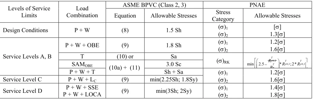
Table 3 Comparison of Load Combinations and stress categories according to ASME BPVC Class 1 and PNAE.
ASME BPVC (Class 1) PNAE Levels of Service
Limits Combination Load Equation Allowable Stresses Stress Allowable Stresses
Design Conditions P + W (9) 1.5 Sm (σ)1
(σ)2
[σ] 1.3[σ] P + T + T1 (12) and (13) (10) or 3.0 Sm
T (12) 3.0 Sm
P + W + T1 (13) 3.0 Sm
(σ)RK
0,2
0,2 0,2
min 2.5 * ; 2*
T
p T T
p p T m R R R R −
Service Level A
P + T + T1 + T2 (11), (12) - (σaF K) -
Service Level B P + W + OBE (9) min(1.8Sm; 1.5Sy)
Service Level C P + W + LC (9) min(2.25Sm; 1.8Sy)
(σ)1
(σ)2
1.2[σ] 1.6[σ]
Service Level D P + W + SSE (9) min(3Sm; 2Sy) (σ)1
(σ)2
1.4[σ] 1.8[σ] Category
P + W + LOCA
Table 4 Comparison of Load Combinations and stress categories according to ASME BPVC Class 2, 3 and PNAE.
ASME BPVC (Class 2, 3) PNAE Levels of Service
Limits Combination Load Equation Allowable Stresses Stress Allowable Stresses
Design Conditions P + W (8) 1.5 Sh (σ)1
(σ)2
[σ] 1.3[σ] P + W + OBE (9) 1.8 Sh (σ)1
(σ)2
1.2[σ] 1.6[σ]
T (10) or Sa
SAMOBE 3.0 Sс
0,2
0,2 0,2
min 2.5 * ; 2*
T
p T T
p p T m R R R R −
Service Levels A, B
P + W + T (10a) + (11) Sh + Sa Service Level C P + W + LC (9) min(2.25Sh; 1.8Sy)
(σ)1
(σ)2
1.2[σ] 1.6[σ] Service Level D P + W + SSE (9) min(3Sh; 2Sy) (σ)1
(σ)2
1.4[σ] 1.8[σ] Category
(σ)RK
Basing on this comparative study the following criteria were proposed to determine intermediate rupture locations (Table 5):
Table 5 Stress and Fatigue Limits for Location of Intermediate Postulated Ruptures.
max 2
( )NOL OBE ( ) 0.8[( )NOL OBE ( ) ]RK
RK a a
σ + + σ ≥ σ + + σ
(1) stress and fatigue limits for
circumferential or longitudinal break: U>0.4 (2)
max 2
( )NOL OBE ( ) 0.4[( )NOL OBE ( ) ]RK
RK a a
σ + + σ ≥ σ + + σ
(3) stress and fatigue limits for
throw-wall crack: U>0.2 (4)
Type of postulated rupture (circumferential or longitudinal break) may be defined with use of the following expressions:
- circumferential break, if z 1.5 ψ σ
σ ≥ ;
- longitudinal break, if 1.5
z ψ σ
σ ≥
- both types of breaks (circumferential or longitudinal) shall be considered if 2 1.5
3 z
ψ σ σ < <
The following load combination shall be used for calculation values of corresponding stress categories:
- (σ)2 stresses: Piping Dead and Live weight + internal pressure + OBE + any other loads specified for
Abnormal Plant Conditions;
- (σ)RK stresses: loads due to system's transient from one service load set to another: thermal expansions and
thermal anchor movements, temperature gradient loads, change of service pressure;
- (σaF)K stresses (stress amplitudes used for fatigue analysis) : the same loads as for (σ)RK stresses + Hydrotest +
50 cycles of OBE.
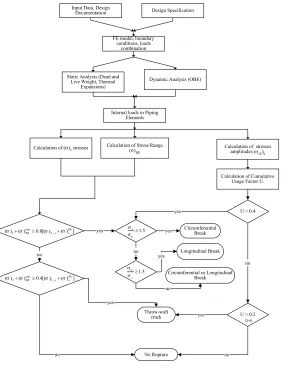
The principal flow-chart of the proposed procedure is shown in Figure 1. According to this scheme two types of analyses shall be carried out for stress check:
- static analyses: determination of internal loads in piping elements under Mechanical and Thermal Expansion loads;
- dynamic analysis: determination of internal loads in piping elements under Seismic Impact corresponded to OBE level or any other dynamic loads prescribed by Design Specification for Abnormal Plant Conditions. Calculation of stress intensity values and value of Cumulative Usage Factor U should be done according to PNAE G-7-002-86 Code requirements.
Comparison of allowable stresses used for determination of rupture location according to PNAE versus ASME approach is shown in Fig. 2. The allowable stresses corresponding to PNAE are calculated according to Eq. (1):
PNAE = 0.8[( )NOL OBE ( ) ]RK
a a
σ + + σ .
For ASME* value the allowable stresses corresponding to ASME NB-3600 (Class 1) Equation 9 for Service Level B were combined with allowances for Equations 10 or 12 –13:
ASME* = 0.8[min(1.8Sm; 1.5Sy) + 3.0 Sm}]
Figure 3 demonstrates comparison of fatigue curves according to PNAE and ASME. As it can be seen from these figures both approaches are satisfactory correlate.
ASME – PNAE COMPARATIVE ANALYSIS
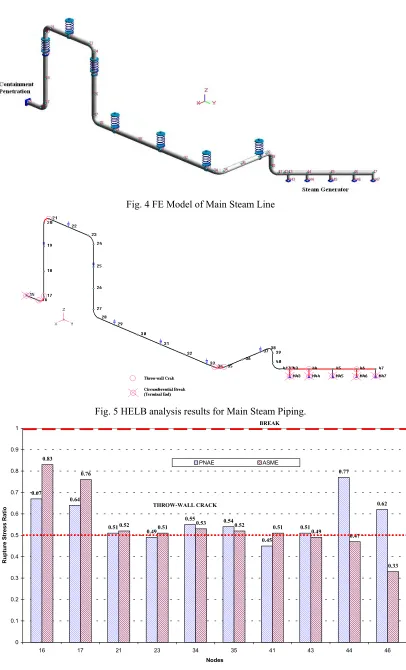
A numerical implementation of the described approach is given for the Main Steam Line of WWER-440 Unit. FE model of this piping is shown in Fig. 4. Seismic Excitation for this study was taken corresponding to 7 balls of MSK-64 scale (ZPGASSE = 0.1g). Numerical results were developed using the specialized Analysis Software Code
0 100 200 300 400 500 600
0 50 100 150 200 250 300 350
Temperature, С
Stresses, MPa
PNAE ASME*
Input Data, Design
Documentation Design Specification
FE model, boundary conditions, loads
combination
Static Analysis (Dead and Live Weight, Thermal
Expansions)
Dynamic Analysis (OBE)
Internal loads in Piping Elements
Calculation of (σ)2 stresses Calculation of Stress Range(σ)
RK
Calculation of stresses amplitudes (σaF)k
Calculation of Cumulative Usage Factor U.
no
no
no no
yes
yes
yes
yes 1.5
z
ψ
σ
σ ≥
1.5 z
ψ
σ
σ ≥
no
no yes
yes
Circumferential Break
Longitudinal Break
Circumferential or Longitudinal Break
Throw-wall crack
No Rupture
max
2 2 _
( ) ( ) 0.8[( ) ( ) ]RK
RK a a
σ +σ ≥ σ +σ
max
2 2 _
( ) ( ) 0.4[( ) ( ) ]RK
RK a a
σ +σ ≥ σ +σ
U > 0.4
U > 0.2 (3-4)
0 100 200 300 400 500 600
0 50 100 150 200
Temperature, С
Stresses, MPa
PNAE ASME*
Fig 1. Flow Chart for High Energy Piping Intermediate Postulated
Rupture Location Procedure Fig. 2 Comparison of allowable stresses used for determination of rupture location. Carbon Steel ST20
Austenitic Steel
Carbon Steel Austenitic Steel
10 100 1000 10000
10 100 1000 10000 100000 1000000
Number of Cycles
Stresses, MPa
PNAE (fig. 5.5)
ASME (Fig. I-9.1)
10 100 1000 10000
10 100 1000 10000 100000 1000000
Number of Cycles
Stresses, MPa
PNAE (fig. 5.6) ASME (Fig. I-9.2-1)
Fig. 4 FE Model of Main Steam Line
Fig. 5 HELB analysis results for Main Steam Piping.
0.67
0.64
0.51
0.49
0.55 0.54
0.45
0.51
0.77
0.62 0.83
0.76
0.52 0.51 0.53 0.52 0.51
0.49
0.47
0.33
0 0.1 0.2 0.3 0.4 0.5 0.6 0.7 0.8 0.9 1
16 17 21 23 34 35 41 43 44 46
Nodes
Rupture Stress Ratio
PNAE
BREAK
THROW-WALL CRACK
ASME
SUMMARY AND CONCLUSIONS
Methodology based on the American Standard ANSI/ANS-58.2 " Design basis for potential of light water NPP against the effects of postulated pipe rupture" was considered for adaptation to the current Russian Regulatory practice and requirements.
Procedure, developed according to rules and requirements of Russian Code PNAE G-7-002-86 for
determination of intermediate postulated High Energy Piping rupture locations was proposed and verified against the analogues approaches of ASME-based ANSI/ANS technique.
NOMENCLATURE
(σ)1 - equivalent membrane stresses
(σ)2 - category of equivalent stresses from
combination of membrane and total bending stresses
2
( )σ NOL OBE+ - stresses of (σ)
2 category from
mechanical and OBE loads
( )σ ψ - tangential stress in pipe wall
( )σ RK - range of equivalent stresses
( )σ Z - longitudinal stress in pipe wall (σaF K) - amplitude of equivalent stresses
[ ]σ - nominal allowable stress (PNAE) Lc - Loads from Design Basis Accident
OBE - Operating Basis Earthquake P - Internal Pressure
T m
R - tensile strength at temperature
0,2
T p
R - yield strength at temperature
Sa - allowable stress (ASME NC-3600) Sh - material allowable stress at
temperature
Sm - allowable design stress intensity SSE - Safe Shutdown Earthquake
Sy - material yield strength at temperature T - loads from thermal expansions T1 - loads from temperature gradient in
longitudinal direction
T2 - loads from temperature gradient along wall thickness
W - mechanical loads
ZPGASSE - Zero Period Ground Acceleration
under SSE
U - Cumulative Usage Factor
REFERENCES
1 Protection against Internal Hazards Other than Fire and Explosions, IAEA Draft Safety Guide, Working ID DS 299, 2002
2 Norms for strength calculations of equipment and pipelines of nuclear power facilities. PNAE G-7-002-86.
3 U.S. Atomic Energy Commission, Regulatory Guide 1.46, Protection against pipe whip inside Containment, May 1973 4 Standard Review Plan, NUREG 0800, part 3.6.1, Plant Design for protection against postulated piping failures in fluid
systems outside Containment, Rev. 2, October 1990
5 Standard Review Plan, NUREG 0800, part 3.6.2, Determination of rupture locations and dynamic effects associated with the postulated rupture of piping, Rev. 1, July 1981