ISSN: 1992-8645 www.jatit.org E-ISSN: 1817-3195
AN APPROACH FOR ASPECT-ORIENTED SKELETON CODE
GENERATION FROM REUSABLE ASPECT MODELS
ABID MEHMOOD, DAYANG N.A. JAWAWI
Department of Software Engineering, Faculty of Computing, Universiti Teknologi Malaysia (UTM)
Email: [email protected], [email protected]
ABSTRACT
Model-driven code generation has been a topic of interest for researchers owing to its several benefits including the anticipated reduction in development effort and delivery time. It has taken a good deal of time to produce techniques that generate executable code in object-oriented programming languages. Aspect-oriented software development techniques, though expected to enhance software development in many ways, still lack approaches that can deliver model-driven code into one of the aspect-oriented programming languages such as AspectJ. In this paper, we present an approach for generation of aspect-oriented code from Reusable Aspect Models. As first step towards the code generation, we have developed a formal and semantically equivalent text-based representation of the aspect models using XML schema notation. Further, we have proposed an approach that takes the XML representation of the aspect models to generate aspect-oriented skeleton code. Currently, our approach can be used to obtain complete aspect structure, interfaces, classes, constructors, fields and stubs of methods specified in the structural part of an aspect.
Keywords: Aspect-Oriented Modeling; Model-Driven Engineering; Aspect-Oriented Code Generation; Reusable Aspect Models
1. INTRODUCTION
Software development industry aims at delivering high quality software products within allocated time. However, with an almost ever growing size and complexity of the product, the goals of quality and on-time delivery tend to become more and more difficult to achieve. Therefore, to prevent them ending up running over schedule, or even worse, relinquishing quality in order to meet the deadlines, software teams are always in need of techniques that can help reducing delivery time, and also lend to raising the quality of the product. In this context, the visual modeling languages such as [1-4] are particularly helpful as they provide modeling and model-checking capabilities at the design level. Nevertheless, since the end product has to be an executable, modeling languages need to be combined with automatic code generation techniques in case their support was to be extended to the implementation and maintenance phases. This way, automatically (and correctly) generated code enhances the benefits of high-level design effort. For this reason, in past, several studies have been conducted to generate or help to generate executable code from high level design models, see for example, Petri Nets [5], Software Cost Reduction (SCR) [6], and Cinderella SLIPPER [6], which use formal notations. Also, some other research work (cf.
[7-10]) has used models developed using UML to generate fully executable code. Similarly, for a long time now, software developers have been using commercial (e.g., IBM Rational Software Architect [11], AjileJ StructureViews [12], MagicDraw UML [13]) as well as open source (e.g., ArgoUML, Eclipse UML2 Tools) CASE tools in order to obtain code stubs.
Aspect-oriented software development techniques [14-16] essentially improve the handing of crosscutting concerns, which correspond to the functionality that cuts across the basic modularization of a software system. Crosscutting concerns usually originate from non-functional requirements such as logging, security, and persistence etc., and thus, if handled using traditional software development approaches (e.g. object-oriented development), lead to problems associated with the phenomena of scattering and tangling of behavior. These phenomena are known as symptoms to show that a concern has not been implemented in a well
modularized way. Specifically, the
development are usually associated with the reusability, maintainability and extensibility of the system, see for example [17-20]. Some other studies have also reported several benefits of
aspect oriented techniques from other
perspectives of development, see for example [17, 18, 21, 22].Owing to this, the current study has been conducted to elaborate a code generation approach that specifically focuses on generation of aspect-oriented code skeletons. For this purpose, Reusable Aspect Models (RAM) [23-26] notation has been used as the input aspect-oriented modeling notation, whereas AspectJ [27] is the target, which is essentially an extension of Java [28] programming language.
This paper is organized in six sections. Following this introduction, Section 2 provides a background for this study by briefly describing the RAM modeling approach, the use of XML schemas in the context of code generation and specifically this study. Section 3 provides a text-based representation of the RAM models in the form of XML schema. Section 4 is dedicated to present the code generation approach. Section 5 describes some related work, and Section 6 concludes the paper while highlighting some future directions for this research.
2. BACKGROUND: REUSABLE ASPECT MODELS, XML AND XML SCHEMAS
2.1. Reusable Aspect Models (RAM)
RAM [23-26] is a multi-view modeling approach that combines different modeling approaches to model aspect-oriented class, sequence and state diagrams into one approach. This allows the use of the most appropriate notation to model each view of a system. The RAM’s notion that it views all of the concerns that are potentially reusable in a single system or a set of systems as aspects makes it different from other aspect-oriented modeling approaches. This essentially enhances, as well as supports, the reusability at all levels of development. Different views, i.e., structure, message, and state views, of a reusable concern are encapsulated in a special UML package, which represents the aspect model. The model comprises of three compartments. These compartments use a UML class, state and sequence diagrams each corresponding to the structural, state, and message view of the modeled concern, respectively.
Classes in the first compartment are not required to be complete, and include methods and attributes which are relevant only to the concern that this aspect model represents. Such
incomplete classes are referred to as mandatory instantiation parameters, and are composed with other classes while instantiation of aspect to obtain complete classes.
Second compartment relates to the state view, which contains UML statechart diagrams to describe the internal states of the class that are relevant within the concern. A complete class in structural view usually has a corresponding standard statechart in state view, whereas an incomplete class is represented here using an aspectual state diagram, which contains a pointcut and an advice. The pointcut part is used to define the states and transitions that are required in target state diagram, whereas the state diagram that replaces the occurrence of pointcut in the target state diagram is defined by the advice part.
Third compartment defines a number of sequence diagrams to describe the message passing between objects of classes in the structural view. Aspect models are used in target model by means of either instantiation or binding directives, which map the mandatory instantiation parameters defined in different views of the aspect model to elements in the target model.
2.2. XML and XML schemas
XML has emerged as a powerful and easy-to-use standard to save and exchange data [29, 30]. It can easily be integrated with other related standards and tools which allow accessing the data stored in XML documents by means of standard application programming interfaces (APIs). XML represents the stored data using XML elements consisting of a start tag, XML attributes, content, and an end tag.
The structure and content of an XML document is defined using an XML schema[31]. Just like the rules and features of a UML diagram, XML schemas define a set of rules describing elements and other markup objects to be defined in an XML document. The standard to define XML schemas is called XML Schema Definition (XSD).
3. XML SCHEMA REPRESENTATION OF RAM MODELS
ISSN: 1992-8645 www.jatit.org E-ISSN: 1817-3195 approaches to define text-based implementation
models, see for example [8, 32-34]. In this section, a text-based representation of RAM models in the form of XML schema is presented. For this purpose, we first elaborate a set of concepts used by a RAM model in a systematic way, and later use the same elaborations to propose the text-based representation. It has to be emphasized here that, since in the current study, our focus in on generation of skeletons only, our discussion in this section and the following section will be limited to structural part of RAM models only.
3.1. Conceptual reference for RAM models The concepts related to structure of a RAM aspects can be divided into two distinct categories, i.e., Core and Structure. We describe both of these in the following.
3.1.1. Core
This category contains the details related to the aspect as a whole. These details include the information on mandatory instantiation parameters, instantiations, and specification of the classes as well as statechart diagrams defined within the structural and state views, respectively.
3.1.2. Structure
Conceptually, the structure of an aspect is defined by a set of classes and interfaces, and relationships among them. In RAM, both types of structural units, i.e., classes and interfaces share some characteristics, and hence it would be desired to capture those common concepts in a general type, which can further be specialized to represent each of these units. A class can either be complete or incomplete, where the latter case would require its composition with some other class by means of binding or an export as a mandatory instantiation parameter. Both interfaces and classes may contain an arbitrary number of functions, however, the specialized types of constructors and methods can only be contained by classes. It is to be noted here that we make a conceptual distinction here between a function and a method. Methods in our representation refer to functions that contain functionality and are commonly associated with a statechart in the state view.
A class in RAM aspect may specify its conceptual relationship with other classes, or interfaces in the model. It may also stipulate the multiplicity of the relationship on both sides. Further, for association relationship, in which roles of the participants on both sides are relevant, we take care of the role name as well.
3.2. XML schema representation
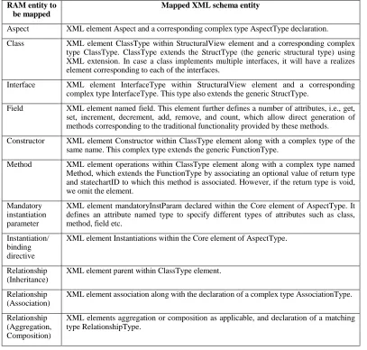
The text-based implementation model, which encapsulates the structural part of RAM models, is presented in this section in the form of XML schema. The schema is a generic representation of RAM aspects, and thus, it can be used in combination with any other related standard, such as XMI. An overview of the specification of mapping from structural view of RAM aspects to XML schema is presented in Table 1, which is mostly self-explanatory. For space reasons, instead of describing the mapping of each of the elements, we provide an overview of implementation of the central concepts in the following. We hope that readers familiar with XML schemas will find the remaining implementation rather straightforward.
An aspect serves as the main encapsulating unit that eventually contains an arbitrary number of classes and interfaces, their contents, and the relationships among them. Moreover, it may also define one or several of the elements as mandatory instantiation parameters while specifying their respective types. These global properties of aspect can be implemented as shown in Lines 1-14 in Figure 1. To enhance reusability and to respect the principles of modular design, we have made extensive use of XML schema complex types in combination with XML elements. Thus, for example, a class is represented by an element of complex type
ClassType, which is an extension of the generic type StructType, representing the core features of a structure shared by classes and interfaces. Classes, interfaces and their corresponding details (fields, functions, parameters, return types etc.) are implemented within the structural view of the schema representation (defined as StructuralView
element, see, e.g., Line 16-35 in Figure 1). As described in Table 1, the field element defines a number of attributes, which allow automatic generation of some methods with predefined semantics, e.g., if get and set attributes are set to true for a particular field, then getter and
setter methods will be generated for that field without the need of any further information.
Following the fields, constructors (in case of class types only) and methods are defined, which stem from a common complex type
FunctionType (see Line 43-50 in Figure 1). This type provides a common base covering the ID, name, and specification of parameters. The type is directly used for the specification of constructors, whereas it is extended by Method
type and the statechart to which this method may be associated, see Line 51-56 in Figure 1.
Once the classes and interfaces are fully declared, we move to defining their relationships. In our implementation, we deal with four different kinds of relationships among structural entities, i.e., inheritance, association, aggregation and composition relationships. Inheritance is
implemented inside the ClassType by
introducing an element named parent, which specifies the parent of this class. The specification of each of remaining three relationships is enclosed within a corresponding element, as shown by Lines 38-40 in Figure 1. We define a complex type
RelationshipType, which is on one hand
extended by AssociationType to define
associations by adding the details specific to associations, e.g., name of the relationship
between two participating entities. On the other hand, aggregation and composition relationships are implemented fully using the instances of the
RelationshipType.
4. CODE GENERATION APPROACH
In this section, we present the code generation approach, which essentially takes the textual representation of RAM models, developed in the form of XML using the schema proposed in the previous section, and generates appropriate aspects, classes, interfaces, relationship implementations and skeletons of methods in AspectJ. A high level algorithmic form of the steps taken to manipulate the XML representation, and obtaining code is shown in Figure 2. We briefly describe the procedure in the
following subsections.
Table 1: Overview Of Mapping From RAM Model Elements To XML Schema RAM entity to
be mapped
Mapped XML schema entity
Aspect XML element Aspect and a corresponding complex type AspectType declaration. Class XML element ClassType within StructuralView element and a corresponding complex
type ClassType. ClassType extends the StructType (the generic structural type) using XML extension. In case a class implements multiple interfaces, it will have a realizes element corresponding to each of the interfaces.
Interface XML element InterfaceType within StructuralView element and a corresponding complex type InterfaceType. This type also extends the generic StructType.
Field XML element named field. This element further defines a number of attributes, i.e., get, set, increment, decrement, add, remove, and count, which allow direct generation of methods corresponding to the traditional functionality provided by these methods. Constructor XML element Constructor within ClassType element along with a complex type of the
same name. This complex type extends the generic FunctionType.
Method XML element operations within ClassType element along with a complex type named Method, which extends the FunctionType by associating an optional value of return type and statechartID to which this method is associated. However, if the return type is void, we omit the element.
Mandatory instantiation parameter
XML element mandatoryInstParam declared within the Core element of AspectType. It defines an attribute named type to specify different types of attributes such as class, method, field etc.
Instantiation/ binding directive
XML element Instantiations within the Core element of AspectType.
Relationship (Inheritance)
XML element parent within ClassType element.
Relationship (Association)
XML element association along with the declaration of a complex type AssociationType.
Relationship (Aggregation, Composition)
ISSN: 1992-8645 www.jatit.org E-ISSN: 1817-3195 <xs:complexType name="AspectType">
<xs:sequence>
<xs:element name="Global">
<xs:complexType><xs:sequence>
<xs:element name="ProjectName" type="xs:string"/> <xs:element name="AspectName" type="xs:string"/> <xs:element name="DependsOn" minOccurs="0"
maxOccurs="unbounded"><xs:complexType><xs:sequence>
<xs:element name="DependsOnAspect" type="xs:string" maxOccurs="unbounded"/></xs:sequence> </xs:complexType></xs:element>
<xs:element name="MandatoryInstParam" minOccurs="0" maxOccurs="unbounded">
<xs:complexType><xs:attribute name="MIPType"><xs:simpleType><xs:restriction base="xs:string"> <xs:enumeration value="class"/><xs:enumeration value="method"/><xs:enumeration value="state"/>
…..
<xs:element name="Instantiations" minOccurs="0">
<!-- ClassInst and StateInst are defined as elements within Instantiations here -->
<xs:element name="StructuralView"> <xs:complexType><xs:sequence>
<xs:element name="ClassType" type="ClassType" maxOccurs="unbounded"/>
<xs:element name="InterfaceType" type="InterfaceType" minOccurs="0" maxOccurs="unbounded"/>
…..
<!-- a base structural type StructType is defined here… -->
<xs:complexContent>
<xs:extension base="StructType"><xs:sequence>
<xs:element name="constructor" type="Constructor" minOccurs="0" maxOccurs="unbounded"/> <xs:element name="data"><xs:complexType><xs:sequence>
<xs:element name="field" maxOccurs="unbounded"><xs:complexType><xs:sequence> <xs:element name="visibility"><xs:simpleType><xs:restriction base="xs:string">
<xs:enumeration value="public"/><xs:enumeration value="protected"/><xs:enumeration value="private"/>
…
<xs:element name="fieldName" type="xs:string"/>
<xs:element name="fieldType" type="xs:string"/>
<xs:element name="initVal" type="xs:string"/></xs:sequence>
<xs:attribute name="get" type="xs:boolean"/><xs:attribute name="set" type="xs:boolean"/>
…
<!-- increment, decrement, add, remove, count attributes are defined in a similar way… --> ….
<!-- different types of relationships -->
<xs:element name="association" type="AssociationType" minOccurs="0" maxOccurs="unbounded"/> <xs:element name="aggregation" type="RelationshipType" minOccurs="0" maxOccurs="unbounded"/> <xs:element name="composition" type="RelationshipType" minOccurs="0" maxOccurs="unbounded"/> ….
<!-- any number of methods can exist here now… -->
<xs:complexType name="FunctionType"> <xs:sequence>
<xs:element name="funcID" type="xs:ID" minOccurs="0"/> <xs:element name="funcName" type="xs:string"/>
<xs:element name="param" minOccurs="0" maxOccurs="unbounded">
<xs:complexType> <xs:attribute name="paramType"/></xs:complexType></xs:element> <xs:element name="isMIP" type="xs:boolean"/>
…..
<xs:complexType name="Method"><xs:complexContent> <xs:extension base="FunctionType"><xs:sequence>
<xs:element name="stateChartID" type="xs:string" minOccurs="0"></xs:element> <xs:element name="returnType" minOccurs="0"><xs:complexType>
<xs:attribute name="isSingular"/>
Figure 1: Excerpt of XML schema representation of a RAM aspect
4.1. Core implementation
The core implementation is primarily related to managing the overall structure of the code (e.g., adding it to an appropriate file structure) and generating code for the global properties of an aspect. The activities in this part typically include creation of source files, creation of
involved in the core implementation, is provided in the following.
a) xGlobal: Set of all elements under
<Global> element in <Aspect>
b) xStructUnit: Refers to the
<StructUnit> element under xGlobal. We use this element to directly obtain the names of classes and interfaces in the structural view to generate source code files.
c) sFile: Source code file with name
obtained from xStructUnit and which has an extension .java.
d) xClassType: Refers to the
<ClassType> element within
xStructView.
e) structView: Set of all elements under
<StructuralView> element in
<Aspect>
f) structName: Refers to the name of
interface or class given in the
<structName> element of
xClassType.
g) xPackageDetails: Refers to
<ProjectName> and <AspectName>
elements in <Global>
h) sPackageDetails: Refers to details of
enclosing package represented in source
code. sPackageDetails is always
generated by appending the value of
<AspectName> to the value of
<ProjectName>.
i) sClass: The interface that is declared at
the highest level in the source file corresponding to each class that exists in the structural view of an aspect. This interface serves as a marker interface, and the fields as well as methods are declared into this interface using inter-type declaration mechanism of AspectJ.
j) sClassAspect: Refers to the aspect that
is declared at the highest level in the source file corresponding to each class that exists in the structural view of an aspect. The name of this aspect is determined by the value of
xStructName and appending the word
Aspect to it. This aspect accompanies the marker interface and is primarily used to add data and functionality to the interface.
k) xParent: Refers to <ParentElement>
within xClassType.
l) declareExtParents: This refers to the
code intended to declare an inheritance relationship between two entities (either classes or interfaces) of the structural model. First entity after the
declareExtParents is considered as the child of the second entity. Here, it has to be ensured that declareExtParents is always used between two homogeneous entities, i.e., classes and interfaces cannot be mixed in a single statement. Actual implementation is carried out by introducing a declare parents statement of AspectJ.
m) xRealizes: Refers to <realizes>
element within xClassType.
n) declareIntParents: This refers to the
code intended to declare that a class
implements an interface. The implementing class precedes the implemented interface in the statement.
o) xInterfaceType: Refers to the
<InterfaceType> element within
xStructView.
p) sInterface: The interface that is
declared at the highest level in the source file corresponding to each interface existing in the structural view of an aspect. This is implemented as a standard interface, rather than a marker one, and includes all the method signatures provided in the aspect’s design.
ISSN: 1992-8645 www.jatit.org E-ISSN: 1817-3195 4.3. Fields implementation
In this section, we describe different elements of algorithm in Figure 2 (see lines 12-13), which are related to implementation of our approach with regards to fields given in classes of an aspect.
a) xField: Refers to <field> element,
which further defines sub-elements to hold all details needed to declare a field for a class.
b) xData: Refers to the <data> element
within the xClassType. This element
exists only once in each class and hosts all the fields for this xClassType.
c) sField: Refers to a field declared in the
source code of the class by means of inter-type declaration mechanism of the AspectJ language. Field in source field is declared by generating different pieces from values of four sub-elements of xField and joining them using space character into one statement, followed by a semicolon. This is described in the following.
Visibility: It is determined by the value of optional element <visibility>. If no value is provided for this element, we assume it to be private. This gives us the first piece to be used in the field declaration.
Field type: It refers to the data type of the field to be declared and is determined by the
<fieldType> element. Field type is appended after visibility.
Field name: It is determined by the value of
<fieldName> element. This name is appended after the field type. It is to be noted here that, since we are using inter-type declaration here, the field name is constructed by combining the name of the interface into which this field is to be introduced (i.e. xStructName) and the field name. Therefore, for example, if the field name is firstField and it is be introduced into an interface named First, the final field name will be
First.firstField.
foreach xStructUnit xGlobal
generate sFile of name xStructUnit
foreach xClassType structView
within sFile of name xClassType.structName
transform xPackageDetails into sPackageDetails generate sClass, sClassAspect from name structName within sClassAspect
if xParent ≠ NULL
add declareExtParents between sClass, xParent if xRealizes ≠ NULL
add declareIntParents between sClass, xParent
foreach xField xData
transform xField into sField
foreach xConstructor xOperations
transform xConstructor into sConstructor
foreach xMethod xOperations
transform xMethod into sMethod
foreach xInterfaceType structView
within sFile of name xInterfaceType.structName
transform xPackageDetails into sPackageDetails generate sInterface from name structName within sInterface
foreach xFunction xOperations
transform xFunction into sFunction
foreach xClassInst xInstantiations
within sFile of name xClassType.structName
declareExtParents between xMappedTo, xMappedFrom
Initial value: It refers to an optional initial value to be set for this field and is determined by the value of <initVal>
element. If provided, an assignment operator is appended to the field name followed by the initial value to be assigned.
4.4. Constructors implementation
This section describes different elements of algorithm in Figure 2 (see lines 14-15), which are related to implementation of our approach with regards to constructors given in classes of an aspect. Since, in our approach, classes are not implemented as plain Java classes, but rather as interfaces along with aspects (because we need to allow their merging with other classes as a result of instantiation and binding directives), constructors implementation needs a special strategy. They cannot be implemented in standard way used for classes, as we are dealing with interfaces here, and an interface is not allowed to have constructors in Java. Therefore, to allow instantiation of our class (which is implemented as a public interface here), we define a private static class within the aspect corresponding to implementation of our class. Next, we declare a
getInstance() method which returns instances of the classes. This is further explained in the following.
Further, it has to be noted here that we follow the Java language principles in dealing with standard constructors. Thus, if an explicit constructor has been provided in the textual implementation of a class, we automatically generate the default constructor also.
a) xConstructor: Refers to a <function
xsi:type=”constructor”> element within xOperations, which is used to declare constructors of the class.
b) sConstructor: Refers to a constructor
defined in the source file of a class within the aspect corresponding to the class. As we stated above, a constructor is implemented
by first generating a private static
class within the aspect corresponding to the actual class in aspect model. The name of this class is obtained by appending the word
Class to the class name. Within this
private class, a method with name
getInstance is declared for each constructor declared in the textual implementation of class in RAM aspect.
Different getInstance methods may
differ in the number and type of input parameters in the way they have been specified in the model. Further details on
generating return type, handling of parameters, adding a return statement are provided in the following section wherein we discuss the same for methods.
4.5. Methods implementation
This section describes different elements of algorithm in Figure 2 (see lines 16-17 and 23-24), which are related to implementation of our approach with regards to methods given in classes and interfaces within an aspect.
a) xOperations: Refers to the
<operations> element within the
xClassType. This element exists only once in a class and contains the whole set of methods and constructors of the class.
b) sMethod: It refers to a method declared in
the source file of interface by using the inter-type declaration. This method is constructed with the help of various pieces of information from the textual representation, and joining them into one unit using space characters. This is described in the following.
Visibility: It is determined by the value of optional element <visibility>. If no value is provided for this element, we assume it to be public. This gives us the first piece to be used in the method declaration.
Return type: It refers to the return type of the method to be declared and is determined by the optional <returnType> element. If no value is provided, we assume the return type to be void. The value of return type is appended to visibility. In case a return type is provided (and is not void), we have to add a corresponding return statement at the end of the method. The handling of “return statement” is described in the following.
Method name: It is determined by the value of <funcName> element. The method name is appended after the return type. It is to be noted here that, since we are using inter-type declaration here, the method name is constructed by combining the name of the interface into which this method is to be introduced (i.e. xStructName) and the method name. Therefore, for example, if the method name is myMethod and it is be introduced into an interface named First, the final method name will be
ISSN: 1992-8645 www.jatit.org E-ISSN: 1817-3195 Parameters: Parameters are determined by
any number of occurrences of the <param>
element. They are constructed by combining the parameter type, which is determined by the paramType attribute and the parameter name. If more than one parameters are found, they are separated by commas. Final string of parameters is added between the pair of parentheses added at the end of method name described above. Following the parameters, a pair of method delimiters, i.e., braces are added.
Return statement: In case a method’s return type is declared to be non-void, a return
statement is added inside the body of the method immediately before the end brace. In order to return a value, first a variable of the return type is declared inside the method body. The actual statement is constructed by starting with the keyword “return”, followed by the name of declared variable, further followed by a semicolon.
c) xFunction: Refers to the <function>
sub-element of <operations> element
within the xInterfaceType. This
element is repeated for each method defined in the interface.
d) sFunction: Here, we try to distinguish
method declarations of interfaces from those of classes that contain an implementation.
sFunction refers to the source code generated for methods that exist in interfaces. sFunction is different from
sMethod described above in that: (1) it is declared within an interface directly, rather than within the aspect corresponding to a marker interfaces, (2) it does not include any implementation, and thus it only specifies a return type, name, and parameters.
4.6. Relationships implementation
In this section, our approach with regards to implementation of relationships among different entities in the structural view of a RAM aspect is described. At a higher level, in structural view of a model, relationships may correspond to class level and/or instance level. In our approach, class level relationships, i.e., inheritance and realization are declared within the body of StructType and thus implicitly belong to both
ClassType and InterfaceType
declarations. Specifically, as given in section 4.1, inheritance and realization relationships are present in the textual model in the form of
xParent and xRealizes. Their implementation is carried out by means of
introducing a declare parents statement within the file corresponding to target class or
interface, see declareExtParents and
declareIntParents in section 4.1.
As far as instance-level relationships, i.e., association, aggregation and composition are concerned, they are implemented by introducing statements for instantiating objects of the participating entities on the target side. It is no more than declaration of fields of the appropriate type on the target side of relationship. The process for declaring fields of a certain type has already been discussed in detail in section 4.3.
4.7. Instantiations/ bindings implementation The implementation of instantiation and binding directives is intended to add code that would allow composition of classes with other classes of the model at execution time. In our approach, both types of these directives are implemented by declaring an inheritance relationship using declare parents statement. Specifically, an instantiation is implemented by having the instantiating entity extend the instantiated entity. Similarly, in case of binding, an extends relationship is defined to make the mapped-to entity inherit from the mapped-from entity. Since the definition of inheritance relationship has been discussed in detail in section 4.1 and 4.6, we have not reproduced it here.
A summary of the various elements used within the algorithm in Figure 2 (line 25 to 27), which are involved in the implementation of instantiations and bindings, is provided in the following.
a) xInstantiations: Refers to the
<Instantiations> element within
xGlobal. This element appears only once in the schema representation of an aspect and hosts all the class and state instantiations.
b) xClassInst: Refers to the
<ClassInst> sub-element of
xInstantiations. This element is repeated for each class instantiation in the model, and it defines instantiations in the form of a pair of from and to elements.
c) xMappedTo: Refers to the
<CMappedFrom> element within
xClassInst. This element contains the name of class from which a mapping has been done.
d) xMappedFrom: Refers to the
xClassInst. This element contains the name of class onto which a mapping has been defined.
5. RELATED WORK
As far as its objective is concerned, the work presented in this paper is closely related to other aspect-oriented code generation work such as the approaches of Bennet et al. [33], Hecht et al. [35], and Groher and Schulze [36]. Also, this work is related, though widely, to the previous work on Reusable Aspect Models by Kramer and Kienzle [37]. In this section, we provide a description of this related work.
Bennet et al. [33] have proposed an approach for aspect-oriented skeleton code generation to complement Formal Design Analysis Framework (FDAF) [38]. FDAF is an aspect-oriented architectural design framework that supports the analysis and design of non-functional requirements. It works at the architectural design layer. The code generation approach uses a graph-based transformation mechanism to transform aspect models into code. In contrast, our work is based on RAM models, which work at the detailed design layer and are capable to model any reusable functionality (not only non-functional requirements) as an aspect. Owing to this, and the point that it is based on a mature aspect-oriented modeling notation, our approach may lead to an integration of aspect orientation and model-driven engineering [39-41].
Hecht et al. [35] generate code from Theme/UML [42, 43] models using a template-based approach that manipulates the model using XSLT transformations. Template-based approaches put several constraints on the modeler since they need a good deal of implementation detail at modeling level. Unlike our work, they have not provided a standard text-based representation of the model that can possibly be used by any transformation mechanism and be integrated into existing code generation tools. Moreover, the use of XSLT in this scenario, instead of customized XML-to-code mechanisms has been reported to have certain limitations, see [30]. Groher and Schulze [36] have also used the mapping algorithm of Theme/UML but to directly manipulate the model in order to obtain code. They have not provided much detail on their technique of handling transformation from model to code. The direct manipulation technique may eventually become extremely difficult to handle when it comes to integration of behavioral models. Moreover, they opted against the use of
XMI, which could allow a standard textual representation of the graphical model.
Kramer and Kienzle [37] have proposed an approach for mapping RAM models to aspect-oriented code. However, their work is limited to the conceptual mapping only, they have not provided any details as regards the code generation from visual models of RAM.
6. CONCLUSION AND FUTURE WORK
Model-driven code generation can support the software development by reducing the coding effort, and consequently the delivery time. Several existing studies in the literature focus on obtaining executable object-oriented code from design models. However, studies on aspect-oriented software development associate many benefits of the approach with directly transforming aspect models into code of aspect-oriented programming languages. In this context, the current paper proposes an approach to generate skeleton code from aspect models developed using the Reusable Aspect Models (RAM) approach.
As first step towards code generation, we have provided a formal, text-based representation of RAM models. The code generation approach takes this text-based representation as input and generates the structural code including the implementation of packages, classes, interfaces, constructors, fields, and method stubs.
We believe that the text-based representation of RAM models using XML schema presented in this paper can be used, the way it is, to extend this work to incorporate code generation from behavioral diagrams such as state and sequence diagrams, which are both supported by RAM models. This can essentially lead to fully executable behavioral code generation in aspect-oriented paradigm.
REFERENCES:
[1] O. Group, "OMG Unified Modeling Language (OMG UML), Infrastructure, V2.1.2," 2007.
[2] G. Booch, Object-Oriented Analysis and Design with Applications (2nd Edition): Addison-Wesley Professional, 1993.
ISSN: 1992-8645 www.jatit.org E-ISSN: 1817-3195 [4] I. Jacobson, Object-Oriented Software
Engineering: A Use Case Driven Approach: {Addison-Wesley Professional}, 1992. [5] S. Philippi, "Automatic code generation from
high-level Petri-Nets for model driven systems engineering," Journal of Systems and Software, vol. 79, pp. 1444-1455, 2006. [6] Y. Rauchwerger, F. Kristoffersen, and Y.
Lahav, "Cinderella SLIPPER: An SDL to C-Code Generator," in SDL 2005: Model Driven. vol. 3530, A. Prinz, R. Reed, and J. Reed, Eds., ed: Springer Berlin / Heidelberg, 2005, pp. 1159-1165.
[7] A. Stavrou and G. A. Papadopoulos, "Automatic Generation of Executable Code from Software Architecture Models," in Information Systems Development, ed: Springer US, 2009, pp. 447-458.
[8] R. Pilitowski and A. Dereziñska, "Code Generation and Execution Framework for UML 2.0 Classes and State Machines," in Innovations and Advanced Techniques in Computer and Information Sciences and Engineering, T. Sobh, Ed., ed: Springer Netherlands, 2007, pp. 421-427.
[9] F. Chauvel and J.-M. Jézéquel, "Code Generation from UML Models with Semantic Variation Points," in Model Driven Engineering Languages and Systems. vol. 3713, L. Briand and C. Williams, Eds., ed: Springer Berlin / Heidelberg, 2005, pp. 54-68.
[10] I. A. Niaz and J. Tanaka, "An Object-Oriented Approach to Generate Java Code from UML Statecharts," International Journal of Computer & Information Science, vol. 6, 2005.
[11] D. Leroux, M. Nally, and K. Hussey, "Rational Software Architect: A tool for domain-specific modeling," IBM Systems Journal, vol. 45, pp. 555-568, 2006.
[12] AjileJ, "AjileJ StructureViews www.ajilej.com," ed, 2011.
[13] NoMagic, "MagicDraw UML,"
ed: www.magicdraw.com/, 2011.
[14] A. Rashid, A. Moreira, J. Araujo, P. Clements, E. Baniassad, and B. Tekinerdogan. (2006, Early aspects: Aspect-oriented requirements engineering and architecture design.
[15] T. Elrad, O. Aldawud, and A. Bader, "Aspect-Oriented Modeling: Bridging the Gap between Implementation and Design " in Generative Programming and Component Engineering. vol. 2487, D. Batory, C.
Consel, and W. Taha, Eds., ed: Springer Berlin / Heidelberg, 2002, pp. 189-201. [16] G. Kiczales, J. Lamping, A. Mendhekar, C.
Maeda, C. Lopes, J.-M. Loingtier, and J. Irwin, "Aspect-oriented programming," in
ECOOP'97 — Object-Oriented
Programming. vol. 1241, M. Aksit and S. Matsuoka, Eds., ed: Springer Berlin / Heidelberg, 1997, pp. 220-242.
[17] J. Hannemann and G. Kiczales, "Design pattern implementation in Java and aspectJ," SIGPLAN Not., vol. 37, pp. 161-173, 2002. [18] A. Garcia, C. Sant'Anna, E. Figueiredo, U.
Kulesza, C. Lucena, and A. v. Staa, "Modularizing design patterns with aspects: a quantitative study," presented at the Proceedings of the 4th international conference on Aspect-oriented software development, Chicago, Illinois, 2005.
[19] A. Hovsepyan, R. Scandariato, S. V. Baelen, Y. Berbers, and W. Joosen, "From aspect-oriented models to aspect-oriented code?: the maintenance perspective," presented at the Proceedings of the 9th International Conference on Aspect-Oriented Software Development, Rennes and Saint-Malo, France, 2010.
[20] W. Harrison, H. Ossher, and P. Tarr, "Asymmetrically vs. symmetrically organized paradigms for software composition," 2002.
[21] L. Fuentes and P. Sánchez, "Execution of Aspect Oriented UML Models," in Model Driven Architecture- Foundations and Applications. vol. 4530, D. Akehurst, R. Vogel, and R. Paige, Eds., ed: Springer Berlin / Heidelberg, 2007, pp. 83-98.
[22] N. Cacho, C. Sant'Anna, E. Figueiredo, A. Garcia, T. Batista, and C. Lucena, "Composing design patterns: a scalability study of aspect-oriented programming," presented at the Proceedings of the 5th international conference on Aspect-oriented software development, Bonn, Germany, 2006.
[23] J. Kienzle, W. Al Abed, F. Fleurey, J.-M. Jézéquel, and J. Klein, "Aspect-Oriented Design with Reusable Aspect Models," in Transactions on Aspect-Oriented Software Development VII. vol. 6210, S. Katz, M. Mezini, and J. Kienzle, Eds., ed: Springer Berlin / Heidelberg, 2010, pp. 272-320. [24] J. Kienzle, W. A. Abed, and J. Klein,
ACM international conference on Aspect-oriented software development, Charlottesville, Virginia, USA, 2009.
[25] W. A. Abed and J. Kienzle, "Information Hiding and Aspect-Oriented Modeling," in Proceedings of the 14th Aspect-Oriented Modeling Workshop, Denver, CO, USA, 2009, pp. 1–6.
[26] J. Klein and J. Kienzle, "Reusable Aspect Models," presented at the 11th Workshop on Aspect-Oriented Modeling, Nashville, TN, USA, 2007.
[27] G. Kiczales, E. Hilsdale, J. Hugunin, M. Kersten, J. Palm, and W. G. Griswold, "An Overview of AspectJ," presented at the Proceedings of the 15th European Conference on Object-Oriented Programming, 2001.
[28] J. Gosling, B. Joy, G. Steele, and G. Bracha, The Java Language Specification, Third Edition: Addison-Wesley Professional, 2005.
[29] L. M. Garhol, Definitive Xml Application Development: Prentice Hall Ptr, 2002. [30] WWWC, "Extensible Markup Language
(XML) 1.0 (fourth edition)," ed: World Wide World Consortium. Available
at: http://www.w3.org/TR/xml/, August
2006 [Online].
[31] E. Van der Vlist, XML Schema: O'Reilly, 2003.
[32] B. Lamancha, P. Reales, M. Polo, and D. Caivano, "Model-Driven Test Code Generation," in Evaluation of Novel Approaches to Software Engineering. vol. 275, L. Maciaszek and K. Zhang, Eds., ed: Springer Berlin Heidelberg, 2013, pp. 155-168.
[33] J. Bennett, K. Cooper, and L. Dai, "Aspect-oriented model-driven skeleton code generation: A graph-based transformation
approach," Science of Computer
Programming, vol. 75, pp. 689-725, 2010. [34] D. Kundu, D. Samanta, and R. Mall,
"Automatic code generation from unified modelling language sequence diagrams," Software, IET, vol. 7, pp. 12-28, 2013. [35] M. V. Hecht, E. K. Piveta, M. S. Pimenta,
and R. T. Price, "Aspect-oriented Code Generation," presented at the XX Brazilian Conference on Software Engineering, 2005. [36] I. Groher and S. Schulze, "Generating
aspect code from UML models," in The Third International Workshop on Aspect-Oriented Modeling, 2003.
[37] M. Kramer and J. Kienzle, "Mapping Aspect-Oriented Models to Aspect-Oriented Code," in Models in Software Engineering. vol. 6627, J. Dingel and A. Solberg, Eds., ed: Springer Berlin / Heidelberg, 2011, pp. 125-139.
[38] L. Dai, "Formal Design Analysis Framework: An Aspect-Oriented Architectural Framework," University of Texas at Dallas, Ph.D Dissertation, 2005. [39] A. Mehmood and D. N. A. Jawawi,
"Aspect-Oriented Code Generation for Integration of Aspect Orientation and Model-Driven Engineering," International Journal of Software Engineering and Its Applications, vol. 7, pp. 207-218, 2013. [40] A. Mehmood and D. N. A. Jawawi, "A
systematic map of integration of aspect orientation and model-driven engineering," in Open Source Systems and Technologies (ICOSST), 2012 International Conference on, Lahore, Pakistan, 2012, pp. 1-6.
[41] T. Cottenier, A. v. d. Berg, and T. Elrad, "Motorola WEAVR: Aspect Orientation and Model-Driven Engineering," Journal of Object Technology, vol. 6, pp. 51–88, 2007. [42] S. Clarke and E. Baniassad,
Aspect-Oriented Analysis and Design: The Theme Approach: Addison Wesley Object Technology, 2005.