Article
1
Sodium Rechargeable Battery with Electrolyte Based
2
on Nafion Membrane
3
Tatiana Kulova 1,*, Alexander Skundin 1, Andrey Chekannikov 2, Svetlana Novikova 3, Daria
4
Voropaeva 4, Andrey Yaroslavtsev3
5
1 A.N. FrumkinInstitute of Physical Chemistry and Electrochemistry of the Russian Academy of Sciences,
31-6
4, Leninskii Prospect, 119071, Moscow, Russia, [email protected]
7
2 Skolkovsky Institute of Science and Technology, 3, ul. Nobel, Moscow, Russia,
8
3 N.S. Kurnakov Institute of General and Inorganic Chemistry of the Russian Academy of Sciences, 31,
9
Leninskii Prospect, 119991, Moscow, Russia,
10
4 Lomonosov Moscow State University, 1 Leninskie gory, 119991, Moscow, Russia
11
* Correspondence [email protected]; Tel.: +7-910-444-92-87
12
13
Abstract: The possibilities of manufacturing batteries with Nafion 117 membranes in the Na+-form
14
intercalated by mixtures of non-aqueous organic solvents used both as electrolyte, separator and
15
binder were investigated. Electrochemical stability of various organic solvent mixtures based on
16
N,N-dimethylacetamide, ethylene carbonate, propylene carbonate, tetrahydrofuran was
17
characterized. It was shown that sodium battery based on Nafion-Na membrane intercalated by
18
mixture of ethylene carbonate - propylene carbonate with Na3V1.9Fe0.1(PO4)3/C positive electrode is
19
characterized by a discharge capacity of ca. 110 mAh g-1 (C/10) at room temperature and shows the
20
ability to cycle for a long time. Batteries with Nafion membrane electrolytes, containing
N,N-21
dimethylacetamide were characterized by capacity fading during cycling, which is due to the
22
interaction of N,N-dimethylacetamide and a negative sodium electrode.
23
Keywords: sodium rechargeable battery, polymer electrolyte, Nafion, cycle stability,
24
electrochemical stability
25
26
1. Introduction
27
Of late, sodium-ion batteries attract keen attention [1–3]. In such batteries, the positive and
28
negative electrodes are made of materials capable of reversibly inserting sodium without the release
29
of a free metallic phase. This is what ensures their safe functioning. Sodium rechargeable batteries
30
differ from sodium-ion counterparts in that sodium metal is used as a negative electrode in such
31
batteries. The theoretical specific capacity of metallic sodium during its anodic dissolution amounts
32
to 1165 mAh g-1, which is much higher than that of intercalation compounds of the negative electrode
33
of the sodium-ion batteries. For example, sodium titanate (Na4Ti3O7), sodiated hard carbon (Na6C),
34
sodiated germanium (Na1.6Ge), sodiated phosphorus (Na3P), have a theoretical specific capacity for
35
sodium extraction of 154, 282, 390, and 804 mAh g-1, respectively [4]. In addition, the potential of
36
sodium metal at its anodic dissolution is noticeably more negative than that of intercalation
37
electrodes during discharge, which contributes to an increase in the discharge voltage of the battery.
38
At the same time, it is known that metallic sodium (as well as metallic lithium) doesn’t able prolonged
39
cycling in liquid electrolytes due to encapsulation and dendritic formation. The latter can lead to a
40
shorting and ignition of the battery with metallic sodium.
41
The use of a solid polymer electrolyte, in principle, can create a battery with a metallic sodium
42
negative electrode, the energy density of which will be higher than that of the sodium-ion battery.
43
Another advantage of solid polymer electrolyte consists in their flexibility, which makes it possible
44
to obtain a large area of electrolyte, and to design batteries of different geometries. In addition, the
45
use of polymer electrolytes reduces the known effect of the volume changes of electrode material
46
during sodium intercalation/deintercalation [5,6].
47
To date, quite a lot of work has been published on the creation and investigation of sodium-ion
48
solid polymer electrolytes [7-10]. The most widespread class of polymer electrolytes are true solid
49
polymer electrolytes [7]. They are based on polymer matrices with dissolved in them sodium salts
50
with a bulky anion. In most cases, the polymer basis of such electrolytes is polyethylene oxide [11].
51
Such electrolytes are characterized by low ionic conductivity at room temperature (ca. 10-5 S cm-1) [12].
52
Replacement of salts with membrane ionogenic groups, such as -SO3‒, -COO‒, etc., as well as the
53
addition of a low-molecular plasticizer, allows higher conductivity values [9, 13]. The most promising
54
polymer electrolytes at present are Nafion-type membranes. Due to the perfluorinated polymer
55
matrix, they have high thermal and electrochemical stability, as well as a high degree of dissociation
56
of functional groups, which ensures high ionic conductivity [14–16].
57
Initially electrolytes based on the Nafion membrane were proposed for lithium-ion batteries [17–
58
24], and later for their sodium-ionic analogs [8,25,26]. Such electrolytes are obtained by transferring
59
Nafion from hydrogen to sodium form (ion exchange in aqueous solutions of sodium salts), followed
60
by removal of water and impregnation with an aprotic solvent. Thus, in fact, they are gel-polymer
61
electrolytes. The principal possibility of creating a sodium battery is mentioned in [25] using the
62
example of the Nafion membrane in sodium form intercalated by a mixture of ethylene carbonate
63
(EC) and propylene carbonate (PC) and Na0.44MnO2 as the active material of the positive electrode.
64
The conductivity of the resulting electrolyte was 0.35 mS cm-1 at room temperature and 1.52 mS cm-1
65
at 70 °C. The laboratory cell was tested at a temperature of 45 °C and demonstrated smaller values of
66
the discharge capacity, but better cycleability than that with liquid electrolyte (1 M NaClO4 in an
EC-67
PC mixture).
68
Recently, the influence of the nature of organic solvents impregnating the membrane in the
69
sodium form, on the ionic conductivity, was investigated [26]. A certain correlation (but not
70
proportionality) was found between the solvent uptake and the ionic conductivity. Membranes,
71
containing N, N dimethylacetamide (DMA), namely EC‒DMA, EC‒diethyl carbonate (DEC)‒DMA,
72
and PC‒DMA‒tetrahydrofuran (THF), are characterized by the highest ionic conductivity (~ 4 mS
73
cm-1 at 30 °C).
74
The purpose of this work was to investigate the possibilities of manufacturing batteries with
75
similar polymer electrolytes based on Nafion membranes in the Na+-form. It was taken into account
76
that not only their ionic conductivity, but also their electrochemical stability and interaction with
77
electrode materials are important features of a polymer electrolytes.
78
2. Results
79
2.1. The composition of the materials obtained
80
The IR spectra of the obtained electrolytes are identical to the spectra presented in the
81
Supplementary of the paper [26]. The presence of organic solvents in membranes is revealed by a set
82
of vibrational frequencies inherent in these solvent molecules. In the frequency range 1600‒1800 cm
-83
1, the C=O stretching vibrations characteristic of organic carbonates (EC, PC, DEC) are observed; at a
84
frequency of ~1640 cm‒1, a band corresponding to the valence vibration of the C=O bond in the DMA
85
molecule can be singled out; the presence of the THF molecule can be detected by the characteristic
86
antisymmetric valence vibration of the ring characteristic of cyclic ethers at ~906 cm‒1. The absence of
87
vibrations of OH groups at ~ 3490 cm‒1 in the IR spectra of the obtained samples indicates that the
88
membranes containing aprotic solvents and their mixtures contain no water or methanol. According
89
to the X-ray diffraction data, Na3V1.9Fe0.1(PO4)3/C is a rhombohedral modification of the NASICON
90
structure (R3c space group). The carbon of the composite is X-ray amorphous. According to
91
elemental analysis, the carbon content in Na3V1.9Fe0.1(PO4)3/C was 8.9% by weight. According to EDX
92
data this composite contains Na, V, P, O, C and Fe. The ratio of the elements Na:V:P:Fe corresponds
93
to the initial load.
94
2.2. The electrochemical stability of polymer electrolyte liquid phase
96
Figure 1 shows CVs for liquid electrolytes based on different solvent mixtures in the potential
97
range from 0.001 to 4.5 V vs. Na+/Na at a potential scan rate of 10 mV s-1. For all electrolytes, the first
98
two cycles of CV are shown. Attention must be drawn to the difference in scale of the ordinates in
99
Figures 1a,b.
100
101
102
103
(a) (b)
104
Figure 1. CVs in 1 М NaClO4 in different solvents at scan rate 10 mV s-1. Solvents compositions and
105
cycle numbers are shown at the figures.
106
107
The lowest electrochemical stability was noted for 1 M NaClO4 in a three-component mixture of
108
PC‒DMA‒THF (Figure 1a). In this case, the anode process proceeds at potentials somewhat more
109
positive than 2 V. The nature of the anode process remains uncertain. Undoubtedly, a certain part of
110
the current is spent for anodic dissolution of aluminum with the possible formation of any complex
111
compounds, since after the registration of the CVs on the aluminum electrode, certain signs of local
112
corrosion that were distributed unevenly over the electrode surface were noticeable. At the same
113
time, an appreciable part of the anode charge is spent on oxidizing the components of the electrolyte,
114
most likely DMA. Similar, but less intense, anode processes at potentials more positive than 2 V are
115
observed for all DMA-containing solvents (Figures 1a,b). The cathode process, which takes place in
116
a 1 M solution of NaClO4 in a three-component mixture of PC‒DMA‒THF at potentials more negative
117
than 3 V, refers to the reduction of oxidation products of DMA in the previous anode semi-cycle,
118
since at the CVs taken in such a solution in the potential range from 0 to 2 V, cathode currents of less
119
than 0.002 mA cm-2 are recorded, i.e. is almost three orders of magnitude smaller than that shown in
120
Figure1a.
121
The highest electrochemical stability from all the electrolytes studied refers to 1 M NaClO4 in a
122
four-component EC‒PC‒THF‒DMA solvent, as well as to solutions in a binary EC‒PC and EC‒THF
123
mixtures (Figure 1 b).
124
The anode processes described above (Figure 1a) are conjugated to a certain passivation of the
125
aluminum electrode. It is possible to trace the passivation of the aluminum electrode in various
126
electrolytes by analyzing Figure 2, which shows CVs for the first six cycles with an increasing range
127
of cycling potentials. As can be seen from the Figure 2a, a 1 M NaClO4 in the EC‒DMA mixture is
128
susceptible to oxidation at potentials more positive than 2 V and causes passivation of the aluminum
129
electrode during cycling. A noticeable electrolyte oxidation at potentials more positive than 2 V is
130
also noted for 1 M NaClO4 in mixtures of EC‒DEC‒DMA (Figure 2b). In the solution of NaClO4 in
131
the four-component EC‒PC‒DMA‒THF mixture, the rate of anodic oxidation is much lower than in
132
previous electrolytes (Figure 2c), and a gradual passivation of the electrode is also observed here. The
133
smallest passivation of the aluminum electrode was noted for a 1 M NaClO4 in a mixture of PC‒
134
DMA‒THF (Figure 2d). When the aluminum electrode is cycled in NaClO4 solutions in mixtures of
135
leads to gradual inhibition of the anodic process. This does not occur in a solution of NaClO4 in the
137
PC‒DMA‒THF mixture (Figure 2d), therefore, when using such a solution, a permanent irreversible
138
capacity loss will appear in the battery, which excludes the use of such a solvent in practical devices.
139
140
141
142
(a) (b)
143
144
(c) (d)
145
Figure 2. Aluminum electrode passivation at cyclic polarization in different electrolytes: (a) 1 М
146
NaClO4 in EC‒DMA, (b) 1 М NaClO4 in EC‒DEC‒DMA, (c) 1 М NaClO4 in EC‒PC‒DMA‒THF, and
147
(d) 1 М NaClO4 in PC‒DMA‒THF
148
The oxidation rate of DMA depends significantly on which mixture it is in (Figures 1,2). The
149
oxidation rate (currents at potentials more positive than 2 V) decreases in the series PC‒DMA‒THF
150
> EC‒DMA > EC‒DEC‒DMA > EC‒PC‒THF‒DMA. This thesis is also confirmed by the results of a
151
cyclic voltammetric study of a 1 M solution of NaClO4 in plain DMA. The corresponding CVs are
152
shown in Figure 3.
153
154
Figure 3. CVs in 1 М NaClO4 in DMA at enlarging potential range. Cycle numbers are shown
The rate of the anodic process in a solution of NaClO4 in plain DMA is seen to be noticeably
156
lower than in a 1 M NaClO4 in a three-component mixture PC‒DMA‒THF. It can be assumed that in
157
this case it is precisely THF that has a de-passivating effect on the aluminum surface.
158
When cyclic voltammetric measurements were carried out, one feature of a 1 M solution of
159
sodium perchlorate in a mixture of PC‒DMA‒THF solvents was disclosed. When this solution was
160
brought into a contact with the sodium electrode, the solution became red-brown, and the staining
161
intensity increased with time. With enough contact time the polymerization of the solution up to
162
solidification took place. It was found by separate experiments that the active component of the
163
solvent in this case was DMA. Interestingly, when other solutions containing DMA (solutions of
164
NaClO4 in mixtures EC‒DMA, EC‒DEC‒DMA and EC‒PC‒DMA‒THF) come into contact with
165
sodium, the color change of the solution was much slower. This fact is most likely explained by the
166
fact that all these solutions contained EC, and when sodium was contacted with such solutions, a
167
fairly strong passive film (solid electrolyte interphase - SEI) formed on its surface, which significantly
168
inhibited the interaction of sodium with the solution. A separate publication will be devoted to the
169
mechanism of chemical interaction of sodium with DMA with a detailed analysis of the products
170
formed.
171
2.3. The rechargeable battery with polymer electrolyte
172
As already mentioned above, the ionic conductivity of the polymer electrolyte is an important
173
but not the determining parameter in deciding the applicability of the electrolyte in sodium batteries.
174
Also, it is essential to operate the positive electrode in contact with a certain polymer electrolyte.
175
Finally, this issue can be solved only by testing the real batteries. In this work, coin cells with polymer
176
membranes intercalated by solvents EC‒PC and EC‒PC‒THF‒DMA were tested. In the case of using
177
a polymer membrane intercalated by an EC‒PC mixture, it was of interest to compare our results
178
with the results given in [25], where the electrolyte was also a Nafion membrane in sodium form
179
intercalated by an EC‒PC mixture, and Na0.44MnO2 was used in positive electrode. It was found by
180
separate experiments that the membrane intercalated by the four-component mixture of EC‒PC‒
181
THF‒DMA has an almost an order of magnitude higher electrical conductivity (more than 4 mS cm-1
182
at 30 °C) compared to the membrane intercalated by EC‒PC (ca. 0.7 mS cm-1at 30 °C) [26], with close
183
electrochemical stability (Table 1).
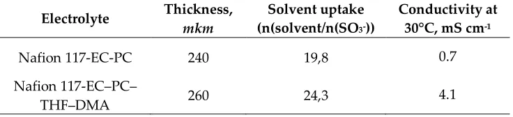
184
Table 1. Physical properties of membrane electrolytes
185
Electrolyte Thickness,
mkm
Solvent uptake (n(solvent/n(SO3-))
Conductivity at 30°C, mS cm-1
Nafion 117-EC-PC 240 19,8 0.7
Nafion 117-EC‒PC‒
THF‒DMA 260 24,3 4.1
186
187
Besides, the selected membranes are characterized by a minimum decrease in conductivity with
188
decreasing temperature.
189
Figure 4 shows the charge-discharge curves for coin cells with polymer electrolytes based on a
190
Nafion 117 membrane intercalated by EC-PC (Fig. 4a) and EC-PC-DMA-THF (Fig. 4b) mixtures.
191
The current density was 0.1 mA cm-2, which corresponded to 10 mA g-1 of active cathode material
192
(Na3V1.9Fe0.1(PO4)3/C). For comparison, the similar coin cell with a liquid electrolyte (1 M NaClO4 in a
193
mixture of EC‒PC) was also tested. The positive electrode in such a cell was made of
194
Na3V1.9Fe0.1(PO4)3/C with a PVDF binder.
195
The charge-discharge curves of coin cells with polymer electrolyte are generally similar to the
196
charge-discharge curves of a battery with a liquid electrolyte, namely, the charge proceeds at a
197
voltage of about 3.5 V, discharge at a voltage of about 3.3 V.
198
200
201
(a) (b)
202
Figure 4. Charge-discharge curves of coin cells with polymer electrolytes based on Nafion 117,
203
intercalated by EC‒PC (a) and EC‒PC‒DMA‒THF (b) mixtures. Current density of 0.1 mA см-2 (10
204
mA g-1)
205
A slight difference consists in the shape of a charging curve on which for a cell with a polymer
206
electrolyte intercalated by the EC‒PC mixture, the second plateau is recorded at a voltage higher than
207
3.9 V. The nature of this plateau is not clear but is unlikely to be associated with the oxidation of
208
solvents. Besides, for a cell with a polymer electrolyte based on a mixture of EC‒PC‒DMA‒THF, the
209
voltage drop at the end of the discharge does not occur so steeply.
210
Comparison of the charge-discharge curves of three cells (Figure 5) shows that when cycling in
211
such a low rate (C/10), the difference in the voltage of the cells does not exceed the experimental
212
discrepancy. This is not surprising. The ohmic voltage drop in the polymer electrolyte with thickness
213
is 0.4 mm, at a current density of 0.1 mA cm-2 is estimated as 8 mV for a cell with polymer electrolyte
214
based on an EC-PC mixture and about 1 mV for a cell with polymer electrolyte intercalated by a
four-215
component solution.
216
217
218
(a) (b)
219
Figure 5. Charge-discharge curves (a) and cycling stability (b) for coin cells with liquid and
220
polymer electrolytes. The capacity is normalized by weight of cathode active material, rate С/10. 1 –
221
1 М NaClO4 in PC‒EC, 2 – Nafion 117 membrane, intercalated by EC-PC mixture, 3 ‒ Nafion 117
222
membrane, intercalated by EC‒PC‒DMA-THF mixture
223
3. Discussion
224
It is worth noting that a battery with a polymer electrolyte based on a Nafion 117 membrane
225
advantageously distinguished by the practical constancy of the discharge voltage, which is explained
227
by the features of the positive electrode from sodium vanado-iron-phosphate. Besides, in the battery
228
in the present work, a polymer electrolyte is used as a binder of the positive electrode, which ensures
229
a more complete utilization of the entire volume of the active material. The initial capacity of a battery
230
with a polymer electrolyte based on a Nafion 117 membrane intercalated by an EC-PC mixture was
231
slightly lower than the corresponding value for a liquid electrolyte battery. However, with further
232
cycling, almost identical values of the discharge capacity were recorded. The specific capacity of the
233
electrode from the composite of sodium vanado-iron-phosphate with carbon, registered in this work
234
when cycling a battery with polymer electrolyte on the basis of a mixture of EC‒PC at room
235
temperature in the C/10 mode was about 100 mAh g-1. Taking into account the content of carbon (8.9
236
wt.%) in the Na3V1.9Fe0.1(PO4)3/C composite, the discharge capacitance is close to the theoretical value.
237
Fig. 6 shows the data on coin cells with liquid and polymer electrolytes cycling.
238
The discharge capacity of a coin cell with a polymer electrolyte based on the Nafion117
239
membrane intercalated by the EC‒PC‒DMA‒THF mixture at the initial cycles was slightly higher
240
than that of the cells with a liquid electrolyte and EC‒PC-based polymer electrolyte. However, with
241
a further cycling for the coin cell with the Nafion 117 membrane intercalated by the EC‒PC‒DMA‒
242
THF mixture, a noticeable capacity fading was recorded, which is due to the chemical interaction of
243
DMA and metallic sodium. The stable operation of a battery with polymer electrolyte based on the
244
Nafion 117 membrane intercalated by a EC-PC mixture for 20 cycles demonstrates the principal
245
possibility of manufacturing a sodium battery with such a polymer electrolyte and a positive
246
electrode based on Na3V1.9Fe0.1(PO4)3/C, capable of long cycling without passivation and excessive
247
degradation. It is worth noting that one of the important challenges in the design of a solid electrolyte
248
battery is to ensure a good contact at the electrode/electrolyte interface. In the case of inorganic solid
249
electrolytes, this is achieved by making composite electrodes (active material/electrolyte/carbon)
250
followed by high-temperature sintering [30–32]. However, this does not completely solve the
251
problem in the case of a thick layer of electrode material and with multiple
252
intercalation/deintercalation, which is accompanied by a change in volume. The use of polymeric
253
binder and polymer electrolyte promotes good cycling by reducing the effect of changes in the
254
volume of electrode material during intercalation/deintercalation. However, in the case of a
non-255
conductive binder, the capacity of such cells is inferior to that of similar cells with liquid electrolyte.
256
Thus, the initial capacity of the electrode based on Na0.44MnO2 at 45 °C in the C/20 mode was inferior
257
to the values obtained with the use of a liquid electrolyte and did not exceed 60 mAh g-1. In this work,
258
the perfluorinated membrane in the Na+ form was used both as an electrolyte and as a binder. As a
259
result, the capacity of the battery with polymer electrolyte based on the EC‒PC mixture is comparable
260
with the corresponding value for a battery with liquid electrolyte. The obtained result indicates a
261
good contact of the polymer electrolyte and particles of the electrode material over the entire
262
thickness of the electrode.
263
The theoretical energy density (based on the weight of active materials only) of sodium battery
264
with a polymer electrolyte and a positive electrode based on the Na3V1.9Fe0.1(PO4)3/C composite
265
amounts to 360 Wh kg-1. With due account for the weight of structural materials and polymer
266
electrolyte of smaller thickness (less than 0.1 mm), one can expect to achieve a practical energy density
267
of 180-200 Wh kg-1, which seems quite optimistic. The use of positive electrodes in a sodium battery
268
with an active material having a higher specific capacity than Na3V1.9Fe0.1(PO4)3 will result in a
269
corresponding increase in the energy density.
270
4. Materials and Methods
271
4.1 Preparation of electrolytes based on Nafion membrane
272
The membranes were made by the same procedure as described in [26]. The commercial Nafion
273
117 membrane manufactured by DuPont was conditioned according to scheme [27], then it was kept
274
for two days in 2 M aqueous NaCl solution with constant stirring. The membrane was then washed
275
vacuum at a temperature of 70 °C for 12 hours. After that, the membrane was aged for 6 hours in
277
methanol at a temperature of 60 °C and again dried under vacuum. Such treatment with methanol
278
contributed to an appreciable expansion of the pores in the membrane. The final operation was the
279
soaking of membranes in mixed solvents. This operation was carried out in a glove box with an argon
280
atmosphere containing less than 1 ppm of oxygen and water vapor. In the present study, the
281
following mixtures of aprotic solvents containing equal volumes of components have been studied:
282
EC - DMA, EC - PC, EC - THF, EC - DEC - DMA, PC - DMA - THF, EC - PC - THF - DMA.
283
4.2 The binder preparation
284
A membrane-based binder was prepared by the following procedure: a membrane was casted
285
from a 5 wt% solution of a Nafion in a proton form in a mixture of lower aliphatic alcohols and water
286
(55:45). Then this membrane was transferred to the Na+ form by ion exchange in a manner like
287
described above. The resulting Nafion-Na membrane was dried in vacuum at 70 °C. The dry polymer
288
was placed in the calculated amount of dimethylformamide (DMFA) to prepare a 10 wt% solution.
289
Dissolution took place at room temperature for 1 day with constant stirring.
290
4.3 The cathode material synthesis
291
The Na3V1.9Fe0.1(PO4)3/C nanocomposite was synthesized by the modified Pechini method
292
according to the procedure described in [28, 29] using V2O5, Fe(NO3)3*9H2O, NaNO3, NH4H2PO4,
293
oxalic acid (a chelating agent and a reducer), ethylene glycol and citric acid. The polycondensation of
294
thylene glycol and citric acid leads to the formation of a polymer matrix that inhibits the growth of
295
the composite particles.
296
4.4 The materials characterization
297
The infrared (IR) spectra of the obtained electrolytes based on Nafion membranes were recorded
298
with a Nicolet iS5 IR spectrometer with a SpecacQuest attachment in the attenuated total reflection
299
mode with a diamond crystal in the frequency range 500-4000 cm-1. The phase composition of the
300
synthesized cathode material was characterized using a Rigaku D/MAX 2200 diffractometer, CuKα
301
radiation in the range of 10-60° 2θ. The carbon content of the composite was determined using a
302
CHNS analyzer EuroEA 3000. The chemical composition of the cathode material was determined
303
using a scanning electron microscope Carl Zeiss NVision 40 equipped with an energy dispersive
X-304
ray (EDX) analyzer Oxford X-Max. Ionic conductivity was measured by impedance spectroscopy
305
using an Elins Z-1500J AC bridge (1 kHz‒2 MHz) on symmetric carbon/membrane/carbon cells.
306
4.5. The electrochemical studies
307
Cyclic voltammetric measurements in liquid electrolytes, i.e. in 1 M solutions of NaClO4 in the
308
above-mentioned mixed solvents (paragraph 4.1) were made to assess the electrochemical stability
309
of the liquid phase of polymer electrolytes based on Nafion membranes. The measurements were
310
carried out in three-electrode cells with an aluminum working electrode (foil 50 μm thick, “Rusal”
311
Co., Russia). The auxiliary and the reference electrodes were made from sodium metal, rolled on a
312
stainless steel mesh. To register cyclic voltammograms (CVs), a potentiostat-galvanostat R-20X8 from
313
“Elins” (Russia) was used. The water content in solvents and electrolyte, determined by coulometric
314
titration by K. Fisher method using a coulometric titrator 917 Ti-Touch (Metrohm) did not exceed 20
315
ppm. The potential scan rate was 10 mV s-1.
316
To evaluate the feasibility of using the polymer electrolytes under investigation in real
sodium-317
ion batteries, coin cells with a polymer electrolyte were tested. For the sake of comparison, similar
318
cells with liquid electrolyte (1 M solutions of NaClO4 in the mixture of EC-PC) were tested as well.
319
For coin cells with polymer electrolyte, positive electrodes contained 80 wt.%
320
Na3V1.9Fe0.1(PO4)3/C, 10% acetylene black as conducting additive and 10% of Nafion-Na dissolved in
321
DMFA as a binder. For coin cells with liquid electrolyte, the positive electrodes contained 80%
322
Na3V1.9Fe0.1(PO4)3/C, 10% acetylene black and 10% PVDF dissolved in N-methylpyrrolidone. The
electrodes were dried, pressed with a pressure of 1 ton cm-2 and further dried at a temperature of 120
324
°C for 8 hours. The amount of active material on the substrate was about 5 mg cm-2. The coin cells
325
were of the 2016 type. Cyclic galvanostatic tests were carried out using a computerized
charge-326
discharge measuring and computing complex AZRVRIK 50 mA-10 V (NTT Buster, Russia). Coin cells
327
were assembled in a glove box with a dry argon atmosphere (JSC Spectroscopic Systems, Russia).
328
The water and oxygen content in the box did not exceed 1 ppm.
329
5. Conclusions
330
In the present work, an estimation was made of the possibility of creating a sodium battery with
331
a polymer electrolyte based on a Nafion membrane intercalated by a mixture of aprotic organic
332
solvents and a positive electrode based on the Na3V1.9Fe0.1(PO4)3/C composite. It has been established
333
that an important factor in the choice of the organic solvent, which impregnates the Nafion membrane
334
in the sodium form, is the electrochemical window. It is shown that sodium batteries with Nafion
335
membrane electrolyte containing dimethylacetamide were characterized by capacity fading during
336
cycling, which is due to the interaction of DMA and a negative sodium electrode. A suitable
337
electrolyte for a sodium battery, in terms of high conductivity and electrochemical stability, is a
338
Nafion membrane in sodium form intercalated by binary solvent ethylene carbonate ‒ propylene
339
carbonate. A battery with this electrolyte showed a discharge capacity of ca. 110 mAh g-1 (C/10) at
340
room temperature and the ability to cycle for a long time.
341
Author Contributions: material synthesis and preparation S.V., D.V.; investigation, D.V., T.K. A.C; data
342
curation, A.C.; writing—original draft preparation, S.V., T.K.; writing—review and editing, A.S. and A.Y.
343
Funding: This research was funded by Russian Science Foundation, grant number 16-13-00024.
344
Conflicts of Interest: The authors declare no conflict of interest.
345
References
346
1. Kundu, D., Talaie, E., Duffort, V., Nazar, L.F. The emerging chemistry of sodium ion batteries for
347
electrochemical energy storage. Angew. Chem. Int. Ed. Engl. 2015, 54, 3431–3448,
348
https://doi.org/10.1002/anie.201410376.
349
2. Hwang, J.Y., Myung, S.T., Sun, Y.K. Sodium-ion batteries: present and future. Chem. Soc. Rev. 2017, 46,
350
3529–3614, https://doi.org/10.1039/c6cs00776g.
351
3. Skundin, A.M., Kulova, T.L., Yaroslavtsev, A.B. Sodium-ion batteries (a review). Rus. J. Electrochem. 2018,
352
54, 113–152. 10. https://doi.org/1134/s1023193518020076.
353
4. Wang L.P., Yu, L., Wang, X., Srinivasan, M., Xu, Z.J. Recent developments in electrode materials for
354
sodium-ion batteries. J. Mater. Chem. A 2015, 3, 9353–9378. https://doi.org/10.1039/c4ta06467d.
355
5. Agrawal, R.C., Pandey, G.P. Solid polymer electrolytes: materials designing and all-solid-state battery
356
applications: an overview. J. Phys. D: Appl. Phys. 2008, 41, 223001.
https://doi.org/10.1088/0022-357
3727/41/22/223001.
358
6. Gao, H., Xue, L., Xin, S., Park, K., Goodenough, J.B. A plastic-crystal electrolyte interphase for
all-solid-359
state sodium batteries. Angew. Chem. Int. Ed. Engl. 2017, 56, 5541–5545.
360
https://doi.org/10.1002/anie.201702003.
361
7. Cao, C., Liu, W., Tan, L., Liao, X., Li, L. Sodium-ion batteries using ion exchange membranes as electrolytes
362
and separator. Chem. Commun. 2013, 49, 11740–11742. https://doi.org/10.1039/C3CC47549B.
363
8. Kulova, T.L., Skundin, A.M. Polymer electrolytes for sodium-ion batteries. Electrochem. Energ. 2018, 18 22–
364
48. https://doi.org/22.10.18500/1608-4039-2018-1-26-47.
365
9. Vignarooban, K., Kushagra, R., Elango, A., Badami, P., Mellander, B.E., Xu, X., Tucker, T.G., Nam, C.,
366
Kannan, A.M. Current trends and future challenges of electrolytes for sodium-ion batteries. Int. J. Hydrog.
367
Energy. 2016, 41, 2829–2846. https://doi.org/10.1016/j.ijhydene.2015.12.090.
368
10. Cao, C., Liu, W., Tan, L., Liao, X., Li, L. Sodium-ion batteries using ion exchange membranes as electrolytes
369
and separators. Chem. Commun. (Camb.). 2013, 49, 11740–11742. https://doi.org/10.1039/c3cc47549b.
370
11. Yaroslavtsev, A.B. Ion transport in heterogeneous solid systems. Rus. J. Inorg. Chem. 2000, 45, S249–S267.
371
12. Armand, M. Polymer electrolytes - an overview. Solid State Ionics. 1983, 9&10, 745–755.
372
13. Yaroslavtsev, A.B. Solid electrolytes: main prospects of research and development. 2016, 85, 1255–1276
374
https://doi.org/1255-1276. https://doi.org/10.1070/rcr4634.
375
14. Phair, J.W.S., Badwal, P.S. Review of proton conductors for hydrogen separation. Ionics. 2006, 12, 103–115.
376
https://doi.org/10.1007/s11581-006-0016-4.
377
15. Karpenko-Jereb, L.V., Kelterer, A.-M., Berezina, N.P., Pimenov, A.V. Conductometric and computational
378
study of cationic polymer membranes in H+ and Na+-forms at various hydration levels. J. Membr. Sci. 2013,
379
444, 127–138. https://doi.org/10.1016/j.memsci.2013.05.012.
380
16. Safronova, E., Golubenko, D., Pourcelly, G., Yaroslavtsev, A. Mechanical properties and influence of
381
straining on ion conductivity of perfluorosulfonic acid Nafion®-type membranes depending on water
382
uptake. J. Membr. Sci. 2015, 473, 218–225. https://doi.org/10.1016/j.memsci.2014.09.031.
383
17. Cai, Z., Liu, Y., Liu, S., Li, L., Zhang, Y. High performance of lithium-ion polymer battery based on
non-384
aqueous lithiated perfluorinated sulfonic ion-exchange membranes. Energy Environ. Sci. 2012, 5, 5690–5693.
385
https://doi.org/10.1039/C1EE02708E.
386
18. Liu, Y., Cai, Z., Tan, L., Li, L. Ion exchange membranes as electrolyte for high performance Li-ion batteries.
387
Energy Environ. Sci. 2012, 5, 9007–9013. https://doi.org/10.1039/C2EE22753C.
388
19. Liu, Y., Tan, L., Li, L. Ion exchange membranes as electrolyte to improve high temperature capacity
389
retention of LiMn2O4 cathode lithium-ion batteries. Chem. Commun. 2012, 48, 9858-9860.
390
https://doi.org/10.1039/C2CC34529C.
391
20. Liang, H.Y., Qiu, X.P., Zhang, S.C., Zhu, W.T., Chen, L.Q. Study of lithiated Nafion ionomer for lithium
392
batteries. J. App. Electrochem. 2004, 34, 1211–1214. https://doi.org/10.1007/s10800-004-1767-0.
393
21. Voropaeva, D.Y., Novikova, S.A., Kulova, T.L., Yaroslavtsev, A.B. Conductivity of Nafion-117 membranes
394
intercalated by polar aprotonic solvents. Ionics. 2018, 24, 1685–1692.
https://doi.org/10.1007/s11581-017-395
2333-1.
396
22. Jin, Z., Xie, K., Hong, X., Hu, Z., Liu, X. Application of lithiated Nafion ionomer film as functional separator
397
for lithium sulfur cells. J. Power Sources. 2012, 218, 163–167. https://doi.org/10.1016/j.jpowsour.2012.06.100.
398
23. Jin, Z., Xie, K., Hong, X., Electrochemical performance of lithium/sulfur batteries using perfluorinated
399
ionomer electrolyte with lithium sulfonyl dicyanomethide functional groups as functional separator. RSC
400
Adv. 2013, 3, 8889–8898. https://doi.org/10.1039/C3RA41517A.
401
24. Gao, J., Sun, C.S., Xu, L., Chen, J., Wang, C., Guo, D.C., Chen, H. Lithiated Nafion as polymer electrolyte
402
for solid-state lithium sulfur batteries using carbon-sulfur composite cathode. J. Power Sources. 2018, 382,
403
179–189. https://doi.org/10.1016/j.jpowsour.2018.01.063.
404
25. Cao, C., Wang, H., Liu, W., Liao, X., Li, L. Nafion membranes as electrolyte and separator for sodium-ion
405
battery. International J. Hydrog. Energy. 2014, 39, 16110–16115.
406
https://doi.org/10.1016/j.ijhydene.2013.12.119.
407
26. Voropaeva, D.Y., Novikova, S.A., Kulova, T.L., Yaroslavtsev A.B. Solvation and sodium conductivity of
408
nonaqueous polymer electrolytes based on Nafion-117 membranes and polar aprotic solvents. Solid State
409
Ionics. 2018, 324, 28–32. https://doi.org/10.1016/j.ssi.2018.06.002.
410
27. Berezina, N.P., Timofeev, S.V., Kononenko, N.A. Effect of conditioning techniques of perfluorinated
411
sulphocationic membranes on their hydrophylic and electrotransport properties. J. Membr. Sci. 2002, 209,
412
509–518. https://doi.org/10.1016/S0376-7388(02)00368-X.
413
28. Chekannikov, A., Kapaev, R., Novikova, S., Tabachkova, N., Kulova, T., Skundin, A., Yaroslavtsev, A.
414
Na3V2(PO4)3/C/Ag nanocomposite materials for Na-ion batteries obtained by the modified Pechini method.
415
J. Solid State Electrochem. 2017, 21, 1615–1624. https://doi.org/10.1007/s10008-017-3524-4.
416
29. Novikova, S.A., Larkovich, R.V., Chekannikov, A.A., Kulova, T.L., Skundin, A.M., Yaroslavtsev, A.B.
417
Electrical conductivity and electrochemical characteristics of Na3V2(PO4)3-based NASICON-type materials.
418
Inorg. Mater. 2018, 54, 794–804. https://doi.org/10.1134/S0020168518080149.
419
30. Aboulaich, A., Bouchet, R., Delaizir, G., Seznec, V., Tortet, L., Morcrette, M., Rozier, P., Tarascon, J.-M.,
420
Viallet, V., Dollé, M. A new approach to develop safe all-inorganic monolithic Li-ion batteries. Adv. Energy
421
Mater. 2011, 1, 179–183. https://doi.org/10.1002/aenm.201000050.
422
31. Delaizir, G., Viallet, V., Aboulaich, A., Bouchet, R., Tortet, L., t Seznec, V., Morcrette, M., Tarascon, J.M.,
423
Rozier, P., Dollé, M. The stone age revisited: building a monolithic inorganic lithium-ion battery. Adv.
424
32. Noguchi, Y., Kobayashi, E., Plashnitsa, L. S., Okada, S., Yamaki, J. Fabrication and performances of all
solid-426
state symmetric sodium battery based on NASICON-related compounds. Electrochim. Acta. 2012, 101 59–
427
65. https://doi.org/10.1016/j.electacta.2012.11.038