Leonid Plotnikov1,*, Alexandr Nevolin1, and Dmitrij Nikolaev1
1Ural Federal University named after the first President of Russia B.N. Yeltsin, Turbines and engines
Department, 620002 Ekaterinburg, ul. Mira, 19, Russian Federation
Abstract. The results of numerical simulation and experimental study of the structure of unsteady flows in pipes with different cross sections are presented in the article. It is shown that the unsteady gas flow in a circular pipe is axisymmetric without secondary currents. Steady vortex structures (secondary flows) are observed in pipes with cross sections in the form of a square and an equilateral triangle. It was found that these secondary flows have a significant impact on gas flows in pipes of complex configuration. On the basis of experimental researches it is established that the strong oscillatory phenomena exist in the inlet pipe of the piston engine arising after the closing of the intake valve. The placement of the profiled plots (with a cross section of a square or an equilateral triangle) in the intake pipe leads to the damping of the oscillatory phenomena and a more rapid stabilization of pulsating flow. This is due to the stabilizing effect of the vortex structures formed in the corners of this configuration.
1 Introduction
It is known that the stagnation zone and reverse flow can be formed in the flowing parts of energy machines and plants (e.g., gas-turbine units or internal combustion engines). It has a negative influence on hydraulic resistance and consequently on the flow characteristics of the system. One of the ways of improving the gas-dynamic characteristics of gas flows is to use pipes with cross sections in the form of a square or an equilateral triangle. Steady vortex structures occur in such pipes, which can stabilize the flow and prevent the formation of stagnant zones and reverse pressure waves.
The structure of gas flows in pipes with different cross sections is investigated in a large number of scientific papers. In Russia, S. S. Kutateladze and I. E. Idelchik [1-3] have actively performed these studies. In their work, it is shown that the gas flow in a long circular pipe is axisymmetric. In such flows, sustainable large-scale turbulent structures (secondary flows) do not occur. Another picture is observed for gas flows in pipes with square or triangular cross plots (Fig. 1).
Secondary flows are formed in the corners of such pipes, which lead to the formation of a steady longitudinal vortex structures. It is determined that isotachs in appearance similar to the shape of the cross section are observed in cross-section of the pipe [1-3].
a b
Fig. 1. Scheme of the secondary flows in a square pipe (a) [1] and in an equilateral triangular pipe (b) [2]
2 Experimental setups and software for numerical simulation
A number of numerical models based on STAR-CCM+ software was designed to study the structure of gas flows in pipes with different configurations. The analyzed pipes were straight channels with different cross sections (see figures below). All pipes had a length of 500 mm and the equivalent hydraulic diameter of 32 mm. Dry air was used as the working medium. The air in the pipes was studied in a turbulent flow regime with an average speed of from 10 to 100 m/s. The mass flow was specified at the inlet of the mathematical model. The output of the mathematical model was defined as the outlet pressure (outlet pressure of the pipes was equal to barometric pressure). k-e turbulence model was used for mathematical modeling. The flow in the pipes was modeled in the unsteady formulation.Experimental setup for experimental investigations of gas-dynamics of the inlet and exhaust processes were designed and manufactured. They were full-scale model of single-cylinder engine of 8.2/7.1. The valve control mechanism for the experimental setups is taken from the engine of the car VAZ-OKA. Valve timing and valve lift of the experimental setups consistent with those for this engine. The drive of a crankshaft was carried out by using an asynchronous motor, the rotational speed of which was regulated by the frequency Converter in the range from 600 to 3000 rpm. A detailed description of the experimental facilities is presented in [4, 5].
To make the necessary measurements on the basis of the analog-to-digital Converter was created an automated data collection system, which passed the experimental data in the personal computer. To determine the speed of the air flow (w) was used constant temperature anemometer [6]. Sensor probes was the nichrome filament diameter of 5 μm and a length of 5 mm. Measuring speed and position of the crankshaft of the engine produced by the tachometer.
3 The results of numerical simulation
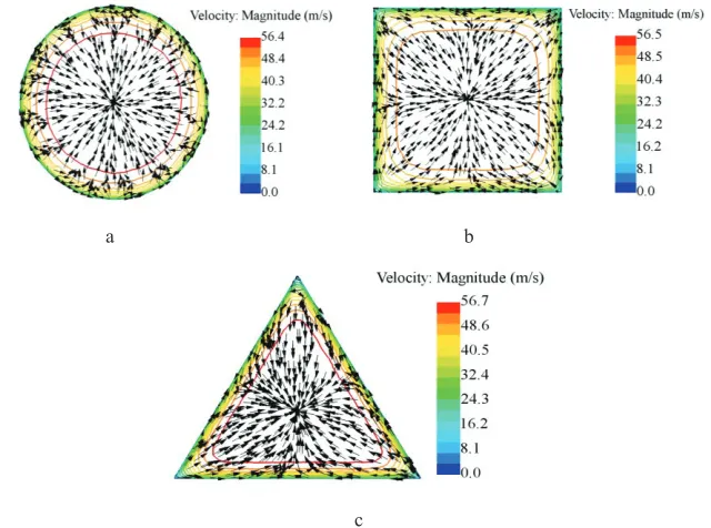
Some results of mathematical simulation of flow in pipes with cross sections in the form of a circle, square and triangle are shown in Fig. 2.
a b
Fig. 1. Scheme of the secondary flows in a square pipe (a) [1] and in an equilateral triangular pipe (b) [2]
2 Experimental setups and software for numerical simulation
A number of numerical models based on STAR-CCM+ software was designed to study the structure of gas flows in pipes with different configurations. The analyzed pipes were straight channels with different cross sections (see figures below). All pipes had a length of 500 mm and the equivalent hydraulic diameter of 32 mm. Dry air was used as the working medium. The air in the pipes was studied in a turbulent flow regime with an average speed of from 10 to 100 m/s. The mass flow was specified at the inlet of the mathematical model. The output of the mathematical model was defined as the outlet pressure (outlet pressure of the pipes was equal to barometric pressure). k-e turbulence model was used for mathematical modeling. The flow in the pipes was modeled in the unsteady formulation.Experimental setup for experimental investigations of gas-dynamics of the inlet and exhaust processes were designed and manufactured. They were full-scale model of single-cylinder engine of 8.2/7.1. The valve control mechanism for the experimental setups is taken from the engine of the car VAZ-OKA. Valve timing and valve lift of the experimental setups consistent with those for this engine. The drive of a crankshaft was carried out by using an asynchronous motor, the rotational speed of which was regulated by the frequency Converter in the range from 600 to 3000 rpm. A detailed description of the experimental facilities is presented in [4, 5].
To make the necessary measurements on the basis of the analog-to-digital Converter was created an automated data collection system, which passed the experimental data in the personal computer. To determine the speed of the air flow (w) was used constant temperature anemometer [6]. Sensor probes was the nichrome filament diameter of 5 μm and a length of 5 mm. Measuring speed and position of the crankshaft of the engine produced by the tachometer.
3 The results of numerical simulation
Some results of mathematical simulation of flow in pipes with cross sections in the form of a circle, square and triangle are shown in Fig. 2.
It was established (Fig. 2), that mathematical modeling confirms the data from the classical literature. Flow in a circular pipe (Fig. 2, a) is axisymmetric without any secondary flows and turbulent structures. The secondary flows (vortical structures) were detected in pipes with cross sections in the form of a square and an equilateral triangle (Fig. 2, b and c). Secondary flows (vortical structures) were formed in the corners of the channels.
a b
c
Fig. 2. Visualization of stationary flows in pipes of different cross sections in the form of isotach and tangential velocity vectors projected from different cross-sections at an initial flow rate of 50 m/s. Cross sections: a) round; b) square; c) triangle
The hypothesis that these turbulent structures (secondary flows) are sustainable and have a significant impact on the flow structure in pipes of complex configuration was tested in the second phase of the research. The complex configuration of the pipe was the changing shape of cross section downstream. The scheme of this configuration with the indication of the control cross-sections is shown in Fig. 3.
Fig. 3. The configuration of the investigated pipe with a triangular plot
The results of numerical simulation of unsteady flow in the pipe with a plot with a cross section of a triangle are shown in Fig. 4.
Fig. 4. Visualization of the unsteady flow in the pipe with a triangular section in the form of isotach and tangential velocity vectors projected from different cross-sections at an initial flow rate of 50 m/s
Thus, we can state that the stable vortex structures (they are formed in the triangular plot) have a significant impact on gas flow and they are stored throughout the pipe. Therefore, we can assume that this effect can be used in intake and exhaust systems of energy machines and plants to stabilize the gas flows.
4 The results of experimental studies
This assumption was tested in the experimental investigation on piston internal combustion engines. The gas flows in the intake and exhaust systems have been investigated on single-cylinder engine.
The geometric configuration of the intake pipe is fully consistent with the dimensions specified in Fig. 3.
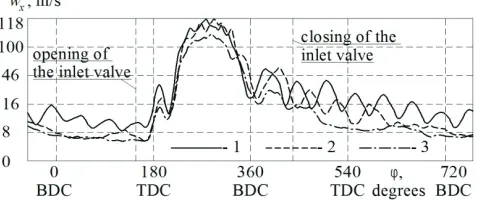
It was found that significant oscillatory phenomena exist in the intake pipe. These oscillatory phenomena occur after closing of the intake valve (Fig. 5). In this case, more rapid damping of oscillatory phenomena is observed when using triangular and square plots in the intake system. According to the authors, this is due to the stabilizing effect of the longitudinal vortex structures generated at the corners of triangular and square cross-sections [4].
Fig. 5. The dependences of the local (lх = 110 mm, d = 32 mm) velocity of the fresh charge wx in the
inlet pipes of different cross-section from the crankshaft rotation angle φ for the rotational speed n = 3000 rpm. Cross section shape: 1 – circle; 2 – square; 3 – triangle
Fig. 4. Visualization of the unsteady flow in the pipe with a triangular section in the form of isotach and tangential velocity vectors projected from different cross-sections at an initial flow rate of 50 m/s
Thus, we can state that the stable vortex structures (they are formed in the triangular plot) have a significant impact on gas flow and they are stored throughout the pipe. Therefore, we can assume that this effect can be used in intake and exhaust systems of energy machines and plants to stabilize the gas flows.
4 The results of experimental studies
This assumption was tested in the experimental investigation on piston internal combustion engines. The gas flows in the intake and exhaust systems have been investigated on single-cylinder engine.
The geometric configuration of the intake pipe is fully consistent with the dimensions specified in Fig. 3.
It was found that significant oscillatory phenomena exist in the intake pipe. These oscillatory phenomena occur after closing of the intake valve (Fig. 5). In this case, more rapid damping of oscillatory phenomena is observed when using triangular and square plots in the intake system. According to the authors, this is due to the stabilizing effect of the longitudinal vortex structures generated at the corners of triangular and square cross-sections [4].
Fig. 5. The dependences of the local (lх = 110 mm, d = 32 mm) velocity of the fresh charge wx in the
inlet pipes of different cross-section from the crankshaft rotation angle φ for the rotational speed n = 3000 rpm. Cross section shape: 1 – circle; 2 – square; 3 – triangle
It was found that we can have a number of advantages due to the placement of the triangular and square plots in the intake pipe in comparison with a pipe of circular cross-section. In particular, there are an increase of the volumetric flow of fresh charge through
Secondary flows (steady vortex structures) in the pipe can stabilize the pulsing flows. This phenomenon can be used in the design of the intake and exhaust systems of energy machines and plants with a view to their gas-dynamic improvement.
The work has been supported by the Russian Science Foundation (grant No. 17-69-00002).
References
1. S.S. Kutateladze, Heat transfer and flow resistance: A Reference Guide (Jenergoatomizdat, Moscow, 1990).
2. I.E. Idel'chik, Manual of hydraulic resistance (Mashinostroenie, Moscow, 1975). 3. I.E. Idel'chik, Aerohydrodynamics of technological devices. Supply, drainage and flow
distribution over the cross section of devices (Mashinostroenie, Moscow, 1983). 4. L.V. Plotnikov, B.P. Zhilkin, Polzunovskij vestnik 3, 178-183 (2012).
5. B.P. Zhilkin, Ju.M. Brodova, Process Improvement in gas path of reciprocating internal combustion engines (Izd-vo Ural, Ekaterinburg, 2015).
![Fig. 1. Scheme of the secondary flows in a square pipe (a) [1] and in an equilateral triangular pipe (b) [2]](https://thumb-us.123doks.com/thumbv2/123dok_us/8127092.1354270/2.482.141.344.84.195/fig-scheme-secondary-flows-square-pipe-equilateral-triangular.webp)