IJEDR1601126
International Journal of Engineering Development and Research (www.ijedr.org)732
Pseudo Linear Enhanced Phased-Locked Loop
(PL-EPLL) based Control Algorithm for Three-Phase
DSTATCOM in Three -Wire Power Distribution
System
1
J.Ramesh,
2T. Aruldoss Albert Victorie
1Research Scholar, 2Associate Professor, 1Department of Electrical and Electronics Engineering,
1Jawaharlal Nehru Technological University, Kakinada, Andhra Pradesh, India
________________________________________________________________________________________________________ Abstract- This paper presents an implementation of pseudo linear enhanced phased-locked loop control algorithm in three-leg Voltage Source Converter (VSC)-based Distribution Static Compensator (DSTATCOM) in three-wire power distribution system. This control algorithm is used for withdrawal of load fundamental active and reactive power components of distorted load currents for estimation of reference source currents. The PWM signals for the VSC based DSTATCOM are derived from the estimated reference source currents. The proposed control algorithm is implemented for mitigating multiple power quality issues such as load unbalancing, reactive power and current. The performance of the DSTATCOM is found satisfactory with the proposed control algorithm under non linear load. The dc bus voltage of the VSC of DSTATCOM has a negligible effect on varying loads.
IndexTerms - Distribution Static Compensator (DSTATCOM), Pseudo Linear Enhanced Phased-Locked Loop (PL-EPLL) Control Algorithm, Voltage Source Converter, Power Quality
________________________________________________________________________________________________________
I.INTRODUCTION
The proliferation of power-electronics-based equipment linear, nonlinear or mixed type of loads has provoked power quality problems in the distribution systems. They cause various types of power quality disturbances such as poor power factor, wave form distortion, fluctuations in voltages or currents in supply systems [1], [2]. Power electronics –based shunt custom power device, called the distribution static compensator (DSTATCOM), injects currents at point of common coupling (PCC) so that load balancing, power factor correction and harmonic filtering can be achieved. There are different topologies reported in the literature for three-phase three wire Voltage Source Converter (VSC) based DSTATCOM [3],[4].The operation of VSC is supported by a dc storage capacitor with proper dc voltage across it. One important aspect of compensation is extraction reference currents from distorted load currents to monitor and eliminate power quality problems. Traditionally, control of a VSC based DSTATCOM utilizes the standard decoupled d-q vector controlled approach for power quality improvement. The performance of the controller has not been analyzed when converter operates beyond the linear modulation limit.
One of the researches focuses on the control algorithm based on instantaneous symmetrical component theory for estimation of reference compensator currents [5]. The researcher had not given attention to reactive power compensation, load balancing and harmonic elimination. Pinaki Mitra et al [6] discuss an adaptive control strategy for DSTATCOM applications in an electric ship power system in order to maintain the voltage at the point of common coupling. The optimal parameters of the controller are obtained by using particle swarm optimization algorithm. An area of adaptive control provides an automatic tuning procedure in a closed loop for the controller parameters [7]. The ability of the control algorithm to extract necessary information from real on line data in order to tune the controller is also used for grid synchronization. Bhim Singh et al.[8] have discussed a comparative study of adaptive control algorithms for DSTATCOM. An adaptive theory based algorithm provides an approach for self control of controllers in real time to achieve a desired level of performance. The selection of parameters for the control algorithm is a vital issue in the works aiming for controlling and mitigating the power quality problems.
IJEDR1601126
International Journal of Engineering Development and Research (www.ijedr.org)733
II.CONFIGURATION OF DSTATCOM AND CONTROL ALGORITHM
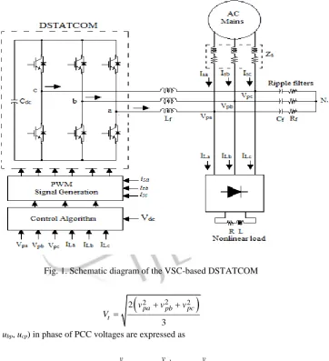
Fig.1. shows a three-phase, three-wire compensated system using VSC topology based DSTATCOM with non linear load. The DSTATCOM consists of six insulated-gate bipolar transistor (IGBT) switches each with an anti parallel diode; three interface inductor (Lf) and dc storage capacitor Cdc. A small resistance Rfand capacitance Cf are connected in series represent the ripple filter installed at point of common coupling (PCC) to attenuate the high frequency switching noise. The source voltages are considered as a stiff source with negligible feeder impedance. The VSC based DSTATCOM operate under the PI control mode due to their simplicity, fast response in order to tack the desired compensator currents. The DSTATCOM injects harmonics/reactive currents into the PCC in such a way as to cancel the harmonics/reactive power component of the distorted load currents [10]-[14]. The primary function of the three-phase DSTATCOM maintains the balanced sinusoidal source currents with unity power factor.
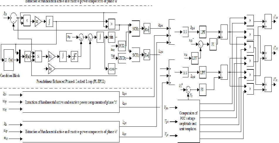
A block diagram of the pseudo linear enhanced phased –locked loop based control algorithm for generation of reference source currents is shown in Fig.2. It is used for computation of fundamental active and reactive power components of reference source currents with unit vector of PCC voltages [15]-[23]. The PCC two phase line voltages measured and converted to three- phase voltages, which is used to estimate in-phase unit templates as well as amplitude of PCC voltages (Vt) as follows
Fig. 1. Schematic diagram of the VSC-based DSTATCOM
2 2 2
2
3
pa pb pc t
v v v
V
(1) The unit templates (uap, ubp, ucp) in phase of PCC voltages are expressed as
,
,
pa pb pc
ap bp cp
t t t
v
v
v
u
u
u
V
V
V
(2)The quadrature unit templates (uaq, ubq, ucq) are estimated by the following set of equations
3
3
, ,
3 2 3 2 3
cp ap cp ap cp
bp bp bp
aq bq cq
u u u u u u u u
u u u
(3)
IJEDR1601126
International Journal of Engineering Development and Research (www.ijedr.org)734
III.EXTRACTION OF AVERAGE FUNDAMENTAL ACTIVE AND REACTIVE POWER COMPONENTS OF SOURCE CURRENTS
In polluted load currents, the fundamental active power components, reactive power components, harmonics and dc components are the major components. The pseudo linear enhanced phased locked loop (PL-EPLL) is used to extract the phase ‘a’ load fundamental current ILa as shown in Fig.2. In the extraction process, phase ‘a’ fundamental load current is subtracted from the load current to estimate the current error signal. In the general PLL and EPLL’s behavior depends on the input signal magnitude. This is a main drawback in cases where the input signal magnitude causes wide range of changes. Once planned for the value of input magnitude, the PLL and EPLL responses tend to unsteadiness when the magnitude becomes high while they become lethargic when the magnitude becomes small. The PL-EPLL is an improved approach of EPLL which is independent of the input signal magnitude The PL-EPLL is described by the subsequent set of equations [24].
3 2
0 1 0 0 0 0 0
0 0
. . .
sin , k ecos , n k ecos
I k e o
I I
(4)
As stated in the succeeding theorem, performance of the PL-EPLL represented by set of Eq.4 does not depend on the signal magnitude. The PL-EPLL internal parameters k1, k2, and k3 are used as respectively, to control steady state and transient performance.
Fig. 2.Reference current generation using Pseudo linear enhanced phased locked loop (PL-EPLL) based control algorithm Theorem: The input current signal ofi Iisini,
dt
i i
0
of the pseudo linear enhanced phased locked loop described by the equations set 4. It has three internal parameters with two equilibrium solutions at the point
I
Ii i i
P1 01,01,01 , , and pointP2
I02,02,02
Ii,i,i
. Both equilibrium points are asymptotically stable and the eigen values of the linearized system are equal to3
1 2 2 2
1 , 2,3 1 , , 2
2 r r r 2 r 2
k
k k
j
(5)
This theorem represent that the transient response of the EPLL does not depend on the input signal magnitude. In the PL-EPLL, the estimated amplitude can be negative so that a correction should be made to drive the actual estimated values. The corrections are made as follows
0
0 0 0 0 0 0
1
sign , ,
2
c c sign I c
I I I S sign I S (6)
In the above equations ‘c’ stands for corrected variable and sign (Io) is the sign function that is equal to 1 when (Io) is positive and equal to -1 when (Io) is negative. The function ‘f ‘is defined as f (Io) =1/Io in the PL-EPLL, it can modified to
0 0 0 I I sign IIJEDR1601126
International Journal of Engineering Development and Research (www.ijedr.org)735
Where ϵ is a small positive number. It can be set at x% of the nominal value of the input signal magnitude, such as x=1 or x=0.5. Thus ϵ=0.01xIn, where In is the nominal value of the input signal magnitude. The function ‘f’ operates like a switch that disconnects the input signal when it is in abnormal conditions. A suggestion for ‘f’
otherwise I I I I I sign I f 0 max min 0 0 0 0 0 0 (8)Where Iomin and Iomax are the minimum and maximum admissible ranges of the input signal magnitude for specific applications. A zero crossing detector (ZCD1) is used with quadrature unit template (uaq) to produce trigger pulse. An output of the zero crossing detector is used with iLpa as the input of sample and hold circuit (SCH1) to extract the amplitude of the active power component of load current phase ‘a’. At the same time, other phases ‘b’ and ‘c’ load fundamental active power currents components iLpb, iLpc also extracted. A another unit of the zero crossing detectors (ZCD2) is used with in phase unit template (uap) to operate the (SCH2) with iLqain order to extract the amplitude of the reactive power component of load current phase ‘a’. Simultaneously other phases ‘b’ and ‘c’ load fundamental active power currents components iLqb, iLqc also extracted. The average magnitude of fundamental active power component of reference source currents is stated as
Lpa Lpb Lpc
LpA i i i
I
3 1
(9)
In the same method, the average magnitude of fundamental reactive power component of reference source currents is also calculated. Its expression is given as
Lqa Lqb Lqc
LqA i i i
I
3 1
(10)
IV.AMPLITUDE OF ACTIVE POWER LOSS OF REFERENCE SOURCE CURRENTS
The amplitude of active power loss component of reference source current is calculated as follows. Here the basic PI controller is used to measure active power loss component. The sensed dc bus voltage is send through a low pass filter to attenuate ripple components. A reference dc bus voltage (V*dc) and filtered dc bus voltage (V
dc) through low pass filter are compared and an error (Vdce) is given to the PI controller. The output of the dc bus PI controller is considered as active power loss component.
I
dcp( )
n
I
dcp(
n
1)
K
dp
v
dce( )
n
v
dce(
n
1)
K v
di dce( )
n
(11) Where Kdp and Kdi are the proportional and integral gain constants of the dc bus PI controller.V.AMPLITUDE OF ACTIVE POWER COMPONENT OF REFERENCE SOURCE CURRENTS
As stated earlier, the amplitude of active power component of reference source current is estimated by addition of active power loss component of DSTATCOM and average amplitude of active power component. The PI controller parameters selection is also very important to obtain a perfect compensation. If any changes in the load it is directly affected dc link voltage of the DC bus in the compensator. The source current is computed by using the following equation
Ispt Idcp ILpA (12) VI.AMPLITUDE OF REACTIVE POWER COMPONENT OF REFERENCE SOURCE CURRENTS
The reactive power components of reference source currents are computed from the output of PCC voltage. A voltage error (Vt) is the difference between the selected reference voltage and sensed amplitude of PCC voltage at the nth sampling instant as given to the PI controller. The output of the PI ac voltage controller is used for maintaining the PCC voltage at a constant value at
nth sampling instant is expressed as [25]
Iacq( )n Iacq(n 1) Kdp
vte( )n vte(n1)
K vdi te( )n (13)Where Kdp and Kdi are the proportional and integral gain constants of the ac bus PI controller. The amplitude of instantaneous value of reactive power components (Isqt) of the reference source current is calculated as
IJEDR1601126
International Journal of Engineering Development and Research (www.ijedr.org)736
V.EXTRACTION OF REFERENCE SOURCE CURRENTS AND GENERATION OF PWM SIGNALSThree-phase reference active and quadrature components of currents are computed using an amplitude of three-phase (a, b, and c) load active and quadrature components, in-phase PCC voltages active and reactive unit templates as
isap Ispt apu , isbp Isptubp, iscp Ispt cpu (15)
isaqIsqt aqu , isbqIsqtubq, iscq Isqt cqu (16)
Finally, the reference source currents (i*sa, i*sb, i*sc) are computed by the summation of reference active and quadrature power components of currents as
* , * , *
sa sap saq sb sbp sbq sc scp scq
i i i i i i i i i
(17)
The reference source currents (i*sa, i*sb, i*sc) and sensed source currents (isa, isb, isc) are given to the error detector for respective phases and each phase current error is amplified using PI controller and their outputs are compared with a carrier signal of 10KHz to generate the PWM signals for VSC based DSTATCOM.
VI.SIMULATION RESULTS AND DISCUSSION
A simulation model of a PL-EPLL based DSTATCOM is developed by using Sim Power System tool boxes available in the MATLAB environment. The performance of the PL-EPLL control algorithm in the time domain for the DSTATCOM is simulated for PFC and ZVR modes of operation. The performance of the control algorithm is discussed under linear and nonlinear loads. Simulation parameters are shown in appendix.
A. Dynamic Performance of DSTATCOM in PFC mode
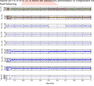
The performance of a VSC based DSTATCOM in PFC mode under linear load is shown in Fig.3. The wave form shows PCC phase voltage (Vs), load currents (IL), source currents (IS), compensator current (iCa,iCb,iCc)and voltage across the capacitor (Vdc) are shown during load variation (at t=0.5s to 0.7s). It shows the satisfactory performance of compensator for the function reactive power compensation and load balancing.
Fig. 3. Dynamic performance of DSTATCOM in PFC mode under linear load
IJEDR1601126
International Journal of Engineering Development and Research (www.ijedr.org)737
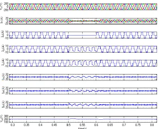
Fig. 4. Dynamic performance of DSTATCOM in PFC mode under varying non linear load
Fig. 5. Dynamic performance of DSTATCOM in ZVR mode under linear load B. Dynamic Performance of DSTATCOM in ZVR mode
The dynamic performance of DSTATCOM in ZVR mode under linear load is shown in Fig.5. It shows different wave forms PCC phase voltage (Vs), source currents (IS), load currents (IL), shunt compensator currents (iCa,iCb,iCc)and voltage across the capacitor (Vdc) during load disturbance (at t=0.5s to 0.7s). Similarly, an uncontrolled rectifier as a nonlinear load is connected to the supply system. The dynamic performance of the wave form shows PCC phase voltage (Vs), load currents (IL), source currents
IJEDR1601126
International Journal of Engineering Development and Research (www.ijedr.org)738
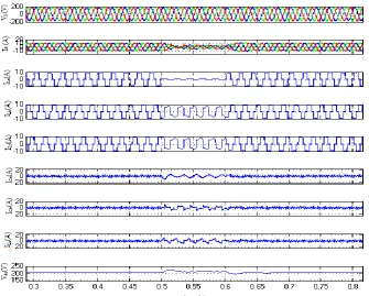
Fig. 6. Dynamic performance of DSTATCOM in ZVR mode under non linear load
IJEDR1601126
International Journal of Engineering Development and Research (www.ijedr.org)739
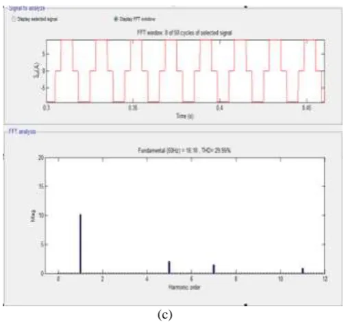
(c)Fig. 7. (a-c). Waveforms, THD and harmonic spectrum at ZVR mode
The dynamic performance of DSTATCOM is discussed through simulation results at different operating mode PFC and ZVR mode under non linear load .The two modes of operation gives the clear function of DSTATCOM. During PFC mode of operation the PCC voltage regulator is not considered. The THD of the source voltage, load current and source current are controlled with in limit. The performance of the DSTATCOM is found satisfactory for the functions of load balancing, power factor correction and harmonic elimination.
Appendix
Ac mains: three-phase, 120V (L-L), 50Hz, Linear load: resistive load bank 69 V (phase), 35Ω and series combination of 14Ω and inductor 80mH load boxes; Non linear load: three phase full- bridge uncontrolled rectifier with R=17.5Ω and L=90mH, dc-bus capacitance: 1650µF;Gains of PI dc voltage regulator: Kp=0.65, Ki=0.1, Gains of PI dc voltage regulator: Kp=0.4, Ki=0.22, reference dc-bus voltage: 220V; interfacing inductor Lf=2.25mH; cutoff frequency of a low pass filter used in dc bus=10Hz
VI.CONCLUSION
In this paper, the PL-EPLL based control algorithm on a DSTATCOM has been implemented in three-phase three wire distribution system. Three-leg VSC has been used as DSTATCOM in this implementation. The control algorithm has been used for computation of reference source currents to generate the gating signals of IGBTs for the VSC based DSTATCOM. Different functions of DSTATCOM such as, harmonic elimination, reactive power compensation and load balancing have been demonstrated. The THD of the source current using the applied control algorithm is well below 5%, the harmonic limit imposed by IEEE-519 standard. From the simulation results, it is concluded that the PL-EPLL based control algorithm has been found satisfactory for compensation of linear and non linear loads.
REFERENCES
[1] A. Ghosh, G. Ledwich, Power Quality Enhancement Using Custom Power Devices(London: Kluwer Acadmeic Publishers., 2002).
[2] H. Akagi, E.H.Watanabe, M. Aredes, Instantaneous Power Theory and applications to power conditioning (New Jersey, USA: John Wiley&sons., 2007).
[3] H.L. Jou, K.D. Wu, J.C. Wu, C.H. Li, and M.S. Huang, Novel Power Converter Topology for Three-phase four-wire Hybrid Power Filter, IET Power Electron, vol. 1n. 1, 2008, pp. 161 – 174
[4] T. Zaveri, B. Bhalija, N. Zaveri, Comparison of Control Strategies for DSTATCOM in Three –Phase, Four-Wire Distribution System for Power Quality Improvement Under Various Source Voltage Conditions. International Journal of Electric Power Energy systems, 43, 2012, pp. 582-594.
[5] M.K. Mishra, K. Karthikeyan, A Fast-Acting DC link Voltage Controller for Three-Phase DSTATCOM to Compensate AC and DC loads. IEEE Transaction on Power Delivery, vol.24 n. 4, 2009, pp. 2291 –2299.
[6] P. Mitra, K. Karthikeyan, An Adaptive Control Strategy for DSTATCOM Applications in an Electric Ship Power System. IEEE Transaction on Power Electronics, vol.25 n. 1, 2010, pp. 95 –104.
[7] S.G. Jorge, C.A. Busada, J.A. Solsona, Frequency Adaptive Discrete Filter for Grid Synchronization under Distorted Voltages. IEEE Transaction on Power Electronics, vol.27 n. 8, 2012, pp. 3584 –3594.
[8] B. Singh, S.K.Dube and S.R. Arya, A Comparative Study of Adaptive Control Algorithms in Distribution Static compensator. IEEE Transaction on Power Electronics, vol.28 n. 8, 2014, pp. 3768 –3778
IJEDR1601126
International Journal of Engineering Development and Research (www.ijedr.org)740
[10] Arpit Kunjbihari Shah, Nirav Vaghela. Shunt Active Power Filter for Power Quality Improvement in DistributionSystems,International Journal of Engineering Development and Research (IJEDR), ISSN: 2321-9939, Vol.1, Issue 2, pp.23 - 27, Sept 2014.
[11]A.Bhattacharaya, C.Chakraborty, S.Bhattacharaya, Shunt compensation: reviewing traditional methods of reference current generation, IEEE Ind. Electron. Mag. 3 (3) (2009) 38-49.
[12]G.Tsengenes, T. Nathenas, G. Adamidis, A three-level space vector modulated grid connected inverter with control scheme based on instantaneous power theory, Simul. Modell. Practice Theory. Elsevier 25 (2012) 134–147.
[13] R. Dipak Bhatt, Mr. Suvas Vora. A Comprehensive Review of Harmonics Effects on Electrical Power Quality, International Journal of Engineering Development and Research (IJEDR), ISSN: 2321-9939, Vol.1, Issue 3, pp.14 - 21, Dec 2014.
[14]Abdul Balikci, Eyup Akpinar, A multilevel converter with reduced number of switches in STATCOM for load balancing, Elect. Power Syst. Res. (123) (2015) 164–173,
[15]S.Iyer, A.Ghosh, A.Joshi, Inverter topologies for DSTATCOM applications- A simulation study, Elect. Power Syst. Res. (75) (2005) 161-170.
[16]Nasser Ahmed Al-Emadi, Concettina Buccella, Carlo Cecati, Hassan Abdullah Khalid, A novel DSTATCOM with 5-level CHB architecture and selective harmonic mitigation algorithm, Elect. Power Syst. Res. (130) (2016) 251-258,
[17] J.Ramesh, T. Aruldoss Albert Victoire, An Adaptive Hysteresis Band Current Controller Based DSTATCOM for Enhancement of Power Quality with Various Loads. International Review of Simulation and Modeling (IREMOS), vol. 6 n. 6, 2013, pp. 1814 – 1820
[18] J. Ramesh, M. Sudhakaran, Enhancement of Power Quality Using Three Phase DSTATCOM for Variable Load. IEEE International conference on EMERGING TRENDS IN ELECTRICAL ENGINEERING AND ENERGY MANAGEMENT” (ICETEEEM-2012) 134-138, 2012.
[19]J.M.Maza-Ortega, J.A.Rosendo-Macias, A.Gomez-Exposito, Reference current computation for active power filters by running DFT techniques, IEEE Trans. Power. del. 25 (3) (2010) 1986-1995.
[20]H.Akagi, Y.Kanazawa, A.Nabae, Instantaneous reactive power theory compensators comprising switching devices without energy storage components, IEEE Trans. Ind. Appl. IA-20 (3) (1984) 625-630.
[21]H.Dirik, M.Ozdemir, New extraction method for active, reactive and individual harmonic components from distorted current signal, IET Gener. Transm. Distrib. 8 (11) (2014) 1767–1777.
[22]S.Golestan, M.Monfared, J.M Guerrero, A novel method for extraction of the reference compensating current for single – phase shunt active power filters, Int. conf. Elect. Eng and Inform. (2011) 17-19.
[23] S.G. Jorge, C.A. Busada, J.A. Solsona, Frequency Adaptive Discrete Filter for Grid Synchronization under Distorted Voltages. IEEE Transaction on Power Electronics, vol.27 n. 8, 2012, pp. 3584 –3594
[24]M. Karimi-Ghartimani, T. Sammad, Enhanced Phased-Locked Loop (EPLL) Structures for Power and Energy Applications, 2 (New Jersey: IEEE Press Series on Microelectronic Systems John Wiley & Sons, Inc., Hoboken, 2014, 22-26).