Elaborate SMART MCNP Modelling Using ANSYS and Its
Applications
Jaehoon Song*, Han-bum SURH, Seung-jin Kim and Bonsueng Koo
Korea Atomic Energy Research Institute, 989-111 Daedeok-daero, Yuseong-gu, Daejeon, 305-353, Korea
Abstract. An MCNP 3-dimensional model can be widely used to evaluate various design parameters such as a core design or shielding design. Conventionally, a simplified 3-dimensional MCNP model is applied to calculate these parameters because of the cumbersomeness of modelling by hand. ANSYS has a function for converting the CAD ‘stp’ format into an MCNP input in the geometry part. Using ANSYS and a 3-dimensional CAD file, a very detailed and sophisticated MCNP 3-3-dimensional model can be generated. The MCNP model is applied to evaluate the assembly weighting factor at the ex-core detector of SMART, and the result is compared with a simplified MCNP SMART model and assembly weighting factor calculated by DORT, which is a deterministic Sn code.
1 Introduction
The shielding design parameters for a safety analysis have been conventionally generated by a deterministic method such as DORT or TORT (Two-and Three-Dimensional Oak Ridge Discrete Ordinates Neutron/Photon Transport Code) [1]. These codes find the solution of the Boltzmann transport equation describing the given system. It uses the method of discrete ordinates to treat the directional variable and finite-difference methods to treat spatial variables. In addition, energy dependence is treated using a multi-group formulation. In order to treat these deterministic codes, a macroscopic cross section is required, such as BUGLE-96 [2], and to apply the cross section into DORT or TORT, the GIP [3] code is needed. BUGLE multi-group libraries are made on the basis of neutron or gamma energy spectrum coming from a commercial reactor. Therefore, there is a limitation to apply the macroscopic cross section into a new type of reactor with different vessel diameters like SMART. DORT or TORT requires a long time to make the geometry input part. GEOSHIELD [4] was developed to easily make a DORT geometry input. The code reads a CAD ‘dxf’ file and converts it into a DORT geometry input, and it can summarize the DORT output file to be easily read by users and provide visualized output summaries.
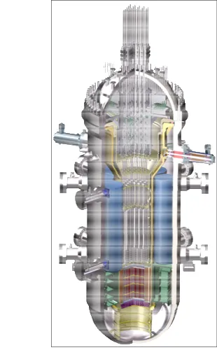
SMART is a small module type reactor of ~330MWth that is being developed at the Korea Atomic Energy Research Institute. It has 57 fuel assemblies, 8 steam generators, 4 coolant pumps, and a pressurizer vessel on top of the reactor. In particular, it has a flow mix header assembly for uniformly mixing S/G outlet coolant as well as neutron/gamma shielding and a flow skirt under the core, as shown in Fig. 1. The enrichment
of the fuel has a range of 2wt% to 4.95wt% depending on the required thermal power, loading patterns, and cycle batch.
SMART has four ex-core detectors (power range) in the core shroud region. Its height is about 2 meters by covering the active core height. As a concept design, the 3 separate detectors are inserted into a hole axially.
Fig. 1. Schmetic view of SMART
order to use these programs, engineers should have a license for them. For example, MCAM has a good technology in that it can analyse overlapped surfaces, divide a complicated cell into several smaller cells, and sometimes find a failed cell and fix it. However, the MCAM sometimes does not give a result (MCNP geometry input with the coolant region) because the void region (coolant region) is generally not described in the CAD file used in the machinery division.
In order to figure out the mentioned problem, the coolant region is modelled before converting CAD into an MCNP input. In addition, the conversion is applied using ANSYS [9].
The ANSYS code is widely used in various engineering fields for an analysis of the structure mechanics, fluid dynamics, and so on. ANSYS also has a function to convert a CAD file (‘*.stp’) into an MCNP input in geometry. Therefore, it is easy to make the MCNP geometry input through cooperation with other engineering fields having an ANSYS code license.
In this paper, the procedures are introduced to generate an MCNP input using ANSYS, and the assembly weighting factor generated from the introduced procedure to be used as the input data in the core protection and monitoring system is evaluated and compared with previous generated design parameters as an application.
2 Procedures
First of all, an STP formatted CAD file is required. The CAD file can be obtained from the machinery division. The structural geometry in the STP file should be simplified by removing insignificant structures such as bolts, nuts, and slightly slanted edges in consideration of the shielding design. In addition, the remaining excluding reactor structures should be filled with coolant. Additionally, it is recommended that a complicated structure like a core support plate and fuel alignment plate should be divided into several parts. In addition, if some model has a reactor core like the SMART reactor model, the core should be modelled with a single cell. The reason for this is that if a complicated core with a fuel rod and cladding is modelled, it is not sure whether the converting is performed well or not. Moreover, it is more powerful and easier to use a repeated structure with a “fill” and “lattice” command in the MCNP for the reactor core modelling.
Secondly, read the STP format file on the design moduler in ANSYS. Then, apply ‘EXPORT’ to the MCNP format. The converted geometry input should be checked using VISED or MCNP plotting in order to confirm whether the geometry input is correctly made or not.
Thirdly, read the converted MCNP input in a text editor. Then, assign the material composition in each cell. In addition, put the core part, which is already manually made by the engineer in a single cell.
Fourthly, a particle transport calculation is done
recommended that the starting particle be located in the centre position in the geometry with a lower material density in order to check the LOST particle from the incorrect modelling.
It is useful if this procedure be applied to other fields, a fusion reactor, a particle accelerator, and a medial system in view of reducing the geometry modelling time.
3 Model description
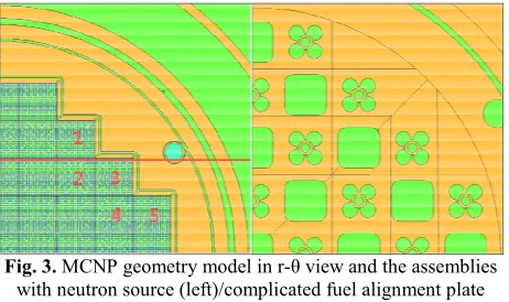
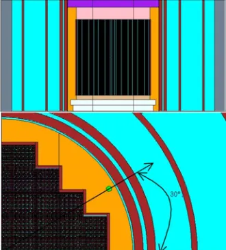
Fig 2 shows a 2-dimensional r-z view (axial direction) along with the red line in Fig. 3 (left), which is r- view in the model. The ex-core detectors are located between the core shroud and flow mixing header assembly. Because the detailed specifications for an ex-core detector is not yet determined, a single cylindrical cell is modelled. It covers the active core region in the axial direction. As shown in Fig. 2, the core shroud is composed of several layers. With this sophistic geometry, the effects of neutrons coming between the shroud layers can be considered. Fig. 3 (right) shows a complicated fuel alignment plate structure. This cell consists of 25 smaller cells and dozens of surfaces. Owing to the ANSYS converting function, this complicated geometry modelling can be performed.
Fig. 2. MCNP geometry model in r-z view showing ex-core detector region (left) / MCNP whole core model(right)
Fig. 3. MCNP geometry model in r- view and the assemblies with neutron source (left)/complicated fuel alignment plate
model (right)
containing 57 fuel assemblies using the introduced method is within about 40 hours.
Table 1. The number of cells and surfaces used in MCNP 3 dimensional model
number
Cells 931 Surfaces 2697
Surface
transformation 556
The neutron sources are assigned in 5 fuel assemblies in which they are most closed to ex-core detectors, due to a lower response of other assemblies with fission watt spectrum, as shown in Fig. 3(left). The number of histories used in this calculation is 4Ƿ1010. Using the ft tally with the ‘SCX’ option, the neutrons coming from 5 assemblies with an assigned neutron source are counted in the cylindrical ex-core detector region cell. The reflective boundary conditions are applied in the y=0 and x=0 plane. The void boundary condition is applied in the radial direction owing to 1/4 core model.
calculations
In this chapter, two types of reference calculations for AWF (assembly weighting factor) are introduced in order to compare the MCNP results generated from the introduced method using ANSYS with a conventional deterministic Sn method and with simplified MCNP 3 dimensional stochastic method. AWF is a relative response fraction for the ex-core detector of each fuel assembly. The AWF is generally used in the core protection and monitoring system (SCOMS/SCOPS) to make a core power distribution.
Fig. 4. DORT 2-dimensional model for assembly weighting factor
Fig. 4. Shows a DORT 2-dimensional r- model treated in reference [10]. The GIP [3] code and BUGLE-96 [2] library are used. The number of fine meshes in the radial and azimuth direction is 249 and 180, respectively. The number of scattering order is P5, and an S8 angular quadrature is used. The boundary conditions are the same with the above introduced MCNP model. The AWF result from the DORT model using adjoint equation is shown in Fig. 5.
Fig. 5. Assembly weigthing factor by DORT
This model has 677 surfaces, 140 cells, and 74 transformation cells. The model is not a 1/4 core but a whole core with 57 fuel assemblies. Therefore, the boundary conditions are all void conditions. The number of histories used is 1Ƿ1010. It has an ex-core detector region, which is divided into 3 parts in the axial direction. The height of each detector is 15cm, and one is 35cm apart. For a comparison with the introduced model, the tally result on the central part is chosen. Fig. 6 shows the MCNP model and Fig. 7 shows the AWF result.
Fig. 6. Previous SMART 3-dimensional model
4
Applications and Reference
4.1. Dort
Fig. 7. Assembly weighting factor by MCNP
Fig. 8. x-z cross section view of SMART total neutron flux distribution by Kcode/Fmesh option using MCNP
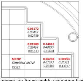
Fig. 8 shows the fmesh tally result in the total energy range. The total relative error on the FT tally with the ‘SCX’ option is less than 0.05% in the ex-core detector region. The assembly weighting factors from the introduced MCNP model are compared with the DORT result and MCNP, which is a 3-dimensional simplified model, as shown in Fig. 9. In Fig. 9, the AWFs (red) by the introduced method are more similar than those by the simplified MCNP. The discrepancy between the introduced method and DORT is about 15%. In addition, the difference in both MCNP methods is over 25%. Actually, this percent is not important due to a small contribution with large difference assemblies.
Fig. 9. Comparison for assembly weighting factors
Using ANSYS, the mcnp geometry input is converted and generated from an “STP” CAD
3-should be reflected in the “STP” file. Complicated structures are automatically divided into smaller cells in ANSYS. The AWFs from the introduced method are compared with AWFs from the previous evaluated simplified mcnp and with AWFs from DORT using an Sn deterministic method.
Further works
In order to calculate a more reliable assembly weighting factor by MCNP and compare it with DORT, the ex-core region will be expanded from one to three. Considering the back scattering effects from a flow mixing header assembly, a variance reduction technique will be attempted. The procedure introduced in reference [11] is a good approach for the case of a whole reactor model. And using reference [6], the assembly weighting factor of the MCAM-MCNP model will be compared with those of the ANSYS-MCNP model
This article was prepared with the help and support of HAN-BUM SURH in the machinery division and SEONG-JIN KIM and BON SEUNG KOO in the SMART PPE development division at the Korea Atomic Energy Research Institute. HAN-BUM SURH provided all sorted ‘stp’ files to convert in MCNP input. SEONG-JIN KIM provided the converted MCNP input using the ‘stp’ file and ANSYS.
References
1. RSICC CODE PACKAGE CCC-543, Two-and Three-Dimensional Discrete Ordinate Transport, Ver. 2.7.3.
2. RSICC DATA LIBRARY COLLECTION BUGLE-96, DLC-185, ORNL, March 28, 1996.
3. W. A. Rhodades, “The Gip Program for Preparation of Ground-Oranized Cross-sections”, ORNL, APR. 13, (1978)
4. K. S. Kim, K. Y. KIM, H. Y. KIM, C. H. Lee and S. Q. Zee, “Development of the GEOSHIELD Program for the Automatic Particle Transport Calculation Using DORT,” Proc. 2006 Autumn Meeting of Korean Association for Radiation Protection, Gyoengjoo, Korea, Nov. 23-24, 94 (2006)
5. D. B. Pelowitz, LA-CP-13-00634, Rev. 0, MCNP6 (TM) USER’S MANUAL Ver. 1.0 (2013)
6. Y. Wu, FDS Team, CAD-based interface programs for fusion neutron transport simulation, Fusion Eng. Des. 84, 1987 (2009)
7. M. Z. Youssef, P. Batistoni, L. Patrizzi, T. Wareing, I. M. Davis, Fusion. Sci. Tech., 52, 801 (2007) 8. R.A. Schwarz, L.L. Carter, T P. Dole, S.M.
Fredrickson, and B.M. Templeton, ęGraphical User Input Interface for MCNP,” Trans. Am. Nucl. Soc.,
69, 401 (1993)
9. ANSYS v14.5 release, 14, Nov. 2012.
10. K. S. Kim, 002-NR301-031, Rev. 00, SMART Assembly Weighting Factor Evaluation, June 5, (2010)