R E S E A R C H
Open Access
Designing digital filter banks using
wavelets
Sergio R. M. Penedo, Marcio Lobo Netto and João F. Justo
*Abstract
In digital filters theory, filtering techniques generally deal with pole-zero structures. In this context, filtering schemes, such as infinite impulse response (IIR) filters, are described by linear differential equations or linear transformations, in which the impulse response of each filter provides its complete characterization, under filter design specifications. On the other hand, finite impulse response (FIR) digital filters are more flexible than the analog ones, yielding higher quality factors. Since many approaches to the circuit synthesis using the wavelet transform have been recently
proposed, here we present a digital filter design algorithm, based on signal wavelet decomposition, which explores the energy partitioning among frequency sub-bands. Exploring such motivation, the method involves the design of a perfect reconstruction wavelet filter bank, of a suitable choice of roots in the Z-plane, through a spectral factorization, exploring the orthogonality and localization property of the wavelet functions. This approach resulted in an energy partitioning across scales of the wavelet transform that enabled a superior filtering performance, in terms of its behavior on the pass and stop bands. This algorithm presented superior results when compared to windowed FIR digital filter design, in terms of the intended behavior in its transition band. Simulations of the filter impulse response for the proposed method are presented, displaying the good behavior of the method with respect to the transition bandwidth of the involved filters.
Keywords:Filtering, Wavelet analysis, Circuit synthesis
1 Introduction
Filter design has been extensively explored in circuit synthesis and signal processing, as a part of circuit the-ory [1–7]. Within this context, one of the major chal-lenges of the IIR filters is determining its respective coefficients: in a digital form, the IIR filters can be de-signed from their analog versions, a procedure that is not easily performed [2, 4]. On the other hand, the FIR filters are more powerful than the IIR ones [4], but they also require more processing power. In this scenario of drawbacks, the frequency partitioning into sub-bands, obtained by the wavelet transform, could be useful: in the wavelet decomposition of a given signal, frequency sub-bands are obtained with peculiar amplitude values, which could be explored in selective filtering techniques. The wavelet filter banks provide the advantage of sep-arating the signal under consideration into two or more signals, in the frequency domain. Since signals can show
different amplitude levels in both time and wavelet transform domains, it is interesting to partition the en-ergy into several frequency sub-bands for several appli-cations. This could be achieved using low-pass or high-pass filters, associated with wavelets respectively with
few or many vanishing moments [8–10]. This apparent
duality could be better described using spectral
factorization [9–12], which allows separating polynomial roots into two corresponding sequences of low-pass fil-ters in a wavelet filter bank, according to a criterion of
perfect reconstruction [12]. The selective filtering
method proposed here designs a wavelet family that de-composes the signal to be filtered into sub-bands fitted in amplitude, obtaining good quantitative results in terms of accuracy of filtering and simultaneously with a low computational cost. Although this technique has been studied in several digital signal processing applica-tions, so far it has not been widely explored in digital circuit theory [13–15], which is the main focus of this
investigation, primarily the digital filter synthesis,
© The Author(s). 2019Open AccessThis article is distributed under the terms of the Creative Commons Attribution 4.0 International License (http://creativecommons.org/licenses/by/4.0/), which permits unrestricted use, distribution, and reproduction in any medium, provided you give appropriate credit to the original author(s) and the source, provide a link to the Creative Commons license, and indicate if changes were made.
* Correspondence:[email protected]
showing the good choice for wavelets in digital filtering applications.
This manuscript is organized as follows. Section2 pre-sents the theory of wavelet filter banks, designed to ob-tain perfect reconstruction. Section 3highlights the role of the multiplicity of a root atz=−1 in digital filter de-sign. Section4presents the methodology for designing a
specific wavelet family based on the spectral
factorization algorithm [8, 12]. Section 5 presents the frequency responses for the designed filter, when com-pared to first-order filtering stages, generally imple-mented with circuit elements. Finally, section VI discusses the results and possible outcomes of this modeling.
2 Methods: wavelet theory and filter banks
In signal processing, a filter bank is an array of band-pass filters that separates the input signal into multiple components, each one carrying a single frequency sub-band of the original signal. For example, an application of a filter bank lies in designing a graphic equalizer, which can attenuate the components differently and re-combine them into a modified version of the original signal [16, 17]. The decomposition process, performed by the filter bank, is labeled analysis (meaning analysis of the signal in terms of its components in each band); the output of the analysis is referred to as a sub-band signal, where each frequency sub-sub-band is related to a specific filter in a bank. The reconstruction process is labeled synthesis, meaning the reconstitution of a complete signal resulting from the filtering process [18]. Particularly in digital signal processing, the term filter bank is also commonly applied to a bank of receivers [19,20]. The difference is that receivers also down-con-vert the sub-bands to a low-center frequency that can be resampled at a reduced rate. The same procedure could be sometimes performed by undersampling the band-pass sub-bands.
The analysis of signals by filter banks requires minim-ally filtering techniques using Fourier analysis [18], which use complex sinusoids as basis functions. How-ever, a difficulty that has often been raised with this ap-proach is that, because of the infinite extent of the basis functions, any time-local information is spread out over the whole frequency axis [18]. Under such constraints, the wavelet basis is a set of functions that can represent signals with good resolution in both time and frequency domains. The wavelet transform is well defined within the multiresolution framework, which allows signal ana-lysis in several scales. Wavelets are characterized by time locality, allowing an efficient capture of transient behav-ior in a signal. Furthermore, the time-frequency
reso-lution trade-off, provided by the multiresolution
analysis, enables a better signal representation over the
Fourier analysis, since it reveals signal aspects that Fou-rier signal representation usually neglects, such as trends, breakdown points, and discontinuities. In this context, a wavelet filter bank is an array of wavelet filters used to decompose a signal into sub-bands over different regions of the frequency spectrum, without losing the time domain characterization as performed by the Fou-rier transform, which is useful in circuit applications.
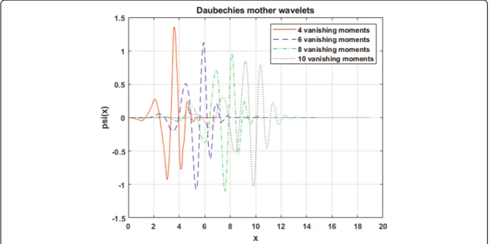
Particularly, wavelets are function sets obtained from a prototype function (labeled mother wavelet) through di-lations and transdi-lations. The general form of a wavelet family is given by
ψj;kð Þ ¼x ψ 2jx−k
;j;k∈Z ð1Þ
where ψj, k(x) is the ‘mother wavelet’, while j and k are
respectively the scale and translation factors.
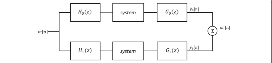
The algebra behind the wavelet filter bank design has been extensively discussed elsewhere [8,9]. A two-chan-nel wavelet filter bank structure involves four filters: the analysis stage has a low-passH0(z) and a high-passH1(z) filter (with h0[n] and h1[n] impulse responses, respect-ively), while the synthesis stage is formed by low-pass G0(z) and high-pass G1(z) filters (with g0[n] and g1[n] impulse responses, respectively), as shown in Fig.1. The output signals of those filters, y0[n] and y1[n], must be decimated by a factor of two, retaining only the even samples, since each filter output contains half of the fre-quency content, but an equal amount of samples as the input signal. The combination of the two outputs con-tains the same frequency content as the input signal, but the amount of data is doubled. Therefore, the downsam-pling procedure, denoted by the operator↓ 2, is applied on filter outputs in the analysis bank:
y0½ ¼n h0½ n x n½ ;v0½ ¼n y0½ 2n ð2Þ
and
y1½ ¼n h1½ n x n½ ;v1½ ¼n y1½ ;2n ð3Þ
where the '∗' symbol is the convolution operator. The input signalx[n] with a fixed lengthq(for analysis purposes) produces two signals, v0[n] and v1[n], with lengthq/2. This analysis step is opposite to the synthesis one: v0[n] and v1[n] are interpolated (by a factor of 2) with zeros in odd samples (denoted by the operator↑2). The results are filtered by G0(z) and G1(z), and their sum gives~x½n:
~x n½ ¼g0½ n ~v0½ þn g1½ n ~v1½ ;n ð4Þ
~vi½ ¼m vim= integer samples), the filter bank allows perfect recon-struction [8, 21, 22]. The conditions for this case are now explained through signal analysis along the filter bank, in the Z-transform domain. An analysis of Eqs. (4) and (5) in theZ-domain leads to
To avoid output aliasing, the following conditions for perfect reconstruction must be defined [11,21]:
G0ð Þz H0ð Þ þz G1ð Þz H1ð Þ ¼z 2z−l ð7Þ
and
G0ð Þz H0ð Þ þ−z G1ð Þz H1ð Þ ¼−z 0 ð8Þ
The anti-aliasing condition from Eq. (8) leads to“ alter-nating signal” constructions [9], corresponding, in poly-nomial terms, to H1(z) =G0(−z) and G1(z) = −H0(−z). Therefore, Eq. (8) is satisfied, and Eq. (7) reduces to an equation of the product filter P0(z) =G0(z)H0(z), such that
P0ð Þz −P0ð Þ ¼−z 2z−l: ð9Þ
This is the key equation to design filters with perfect reconstruction [9], in which the left term is an odd
func-tion, so l must be odd. This means that the only odd
term inP0(z) is equal toz−l. The solution of Eq. (9) leads
This formulation motivates the study of digital filter design from a perspective of filter root analysis, which is explored in the following sections.
3 Root analysis in digital filters
Digital filters have been widely used in signal processing and communication systems, in applications such as channel equalization, noise reduction, radar, audio and video processing, biomedical signal processing, and ana-lysis of economic data [2, 3, 23–25]. In those examples, the roots of the digital filters play a major role in their design. Their location in the Z-plane allows the designer to establish specific applications, mainly to confine a sig-nal in a prescribed frequency band as in low-pass, high-pass, and band-pass filters; to decompose a signal into two or more sub-bands as in filter-banks, graphic equal-izers, sub-band coders, and frequency multiplexers; to modify the frequency spectrum of a signal as in tele-phone channel equalization and audio graphic equal-izers; to model the input-output relationship of a system, such as telecommunication channels, human vocal tract, and music synthesizers [26]. Those features could be directly transferred to circuit theory without loss of generality.
Here, the task of building filter prototypes to select specific frequency components in a signal has been pri-oritized. We explored the number of zeros (roots of a polynomial filter) of digital filtering structures, placed at z= −1. Particularly, we focused on the use of perfect re-construction filter banks, as those schemes are formed by linear phase analysis and synthesis filters, therefore avoiding the occurrence of undesired disturbances due to phase shifting [26].
The design of a perfect reconstruction filter bank could be synthesized in three steps [11,27]:
i) Selection of a generic polynomialP0(z) that satisfies Eq. (9);
ii) Factorization of the polynomialP0(z) into two polynomialsG0(z) andH0(z), whereH0(z) contains all zeros only atz=−1; and
iii) Determination of impulse responses of low-pass filtersh0[n] andg0[n], as well as the ones for high-pass filtersh1[n] = (−1)ng0[n] andg1[n] = (−1)n+ 1h
0[n], through the“alternating signal”construction [7].
According to digital filter theory [2], the magnitude response |H(z)| of a low-pass digital filter must vanish
at the digital frequency Ω=π rad/sample. In Z-plane,
such case corresponds to the condition z=e−iπ=−1, ensuring that the high-frequency components of the input signal are essentially canceled. This condition, H(−1) = 0, is relevant in wavelet theory [7, 8, 16, 17].
In a filter bank, a root located atz=−1, with multiplicity p, imposes a major role: the associated wavelet functionψj,
k(x) haspvanishing moments, which represents a criterion
on how those functions decay toward infinity [8]:
Z∞
−∞
xmψj;kð Þx dx¼
Z∞
−∞
xm2j=2ψj;k2jx−kdx
¼0 ;m<p; ð15Þ
wherejandkdenote the dilation and translation wavelet
factors, respectively. Figure 2 shows the Daubechies
wavelets [15], generally used in wavelet filter design, re-lated to vanishing moments.
Although the formulation to design perfect recon-struction wavelet filters is given above, there is no expli-cit criterion on which design is the best choice. One feature that gives some information on the performance of the designed filters, with respect to their behavior on pass and transition bands, is based on the multiplicity of zeros at z=−1, which ensures the orthogonality of the designed wavelets and could be explored [4], being use-ful to determine the number of vanishing moments of that wavelet family.
Therefore, the p value assumes an important role in
wavelet filter design, defining the form of the transition band in filtering: a large p value characterizes low-pass filters with a wider passband and a narrower transition band. In contrast, a wavelet function with a few
vanish-ing moments (a low multiplicity p for roots at z=−1)
produces low-pass filters with a wider transition band and a narrower passband. Exploring those features is convenient to select properly the filter to be used ac-cording to the nature of the input signal.
4 Multiresolution selective filter design
Over the last few years, the expansion of circuits equa-tions on wavelet basis has been explored [28, 29]. This resulted from the fact that expanding these equations on a wavelet basis gives algebraic systems that can be con-veniently solved (by numerical techniques), producing accurate results with a low-computational cost. This
feature is particularly evident when irregular signals (such as fast transients) are considered, since the wavelet basis gives a concise representation (i.e., characterized by a reduced number of coefficients). In fact, the Daube-chies wavelets, on the interval in which the representa-tion of circuits equarepresenta-tions has been found [30], are the most suitable wavelet basis for this type of problems. They are orthonormal wavelet basis, characterized by a
certain number of vanishing moments [31], since they
offer the best efficiency in terms of accuracy versus cal-culation time.
Nevertheless, the uneven distribution of signal energy in the frequency domain has made signal decomposition into wavelets an important practical problem. Rate-dis-tortion theory shows that the uneven spectral nature of real-world signals can provide the basis for source
com-pression techniques [32]. The basic concept explored
here refers to dividing the signal spectrum into sub-bands, in a manner that the sub-spectrum with more en-ergy content deserves higher priority for filtering. For example, a slowly varying signal will have predominantly low-frequency components. Therefore, the low-pass sub-bands contain most of its total energy. If one filters the high-pass analysis sub-bands and reconstructs the signal, it is expected that very little or negligible reconstruction error occurs after this analysis/synthesis operation. The decomposition of the signal spectrum into sub-bands provides the mathematical basis for an important and desirable feature in the signal analysis: the monitoring of signal energy components within the sub-bands is pos-sible, as the sub-band signal can be ranked and proc-essed independently.
Under such considerations and after emphasizing the relevance of roots atz= −1 in the previous section, the filter bank design can be analytically developed, specific-ally through spectral factorization of a polynomial filter [9, 22]. The construction of a filter bank, according to that method, requires the computation of the roots of a particular product filter
P<0D>ð Þ ¼z 1þz−12ðDþ1ÞQDð Þ;z ð16Þ
whereQD(z) is a Laurent polynomial with degreeDand
2Droots [7].
In order to separate real from complex roots of the polynomial QD(z), a possible form of P<0D>ðzÞ is here
proposed using [30], such that
P<0D>ð Þ ¼z 1þz−12ðDþ1ÞU z−1;zi
are auxiliary functions obtained from the separation of P<D>
0 ðzÞ into roots at z=−1, complex and real roots,
and where ncq and nrd are respectively the numbers of
quadruple complex factors and of double real factors in QD(z). In fact, the precise separation of roots into two
sets, the ones located at z=−1 and the ones located in other regions in Z-plane, is the key element of the pro-posed algorithm for filter circuits design. It can be shown that ncq=D/2 and nrd=Dmod 2 [33, 34], where
‘mod’ represents the modulus operator. The Eqs. (16), (17), (18), (19) could be interpreted as
i) For an arbitrary polynomialF(z) withNcoefficients, there areN−1 roots, from which a subset ofK integer roots, 0≤K≤N−1, may be placed atz= − 1;
ii) In spectral factorization, the polynomial of the product filterP<0D>ðzÞwithNP= 4D+ 3 coefficients andKp= 2D+ 2 roots atz=−1 is factorized into polynomials; and
iii) Each polynomial corresponds to analysis low-pass filter,H0(z), and synthesis low-pass filter,G0(z), respectively, withNhandNgcoefficients andKhand
Kgroots atz= −1.
This factorization leads to the following constraint for the roots atz=−1:
Np¼NhþNg−1 ð20Þ
and
Kp¼KhþKg: ð21Þ
The wavelet family, chosen in the design due to its lin-ear phase, suitable for circuit design [30], is the symmet-rical orthogonal one, which requires [8,11]:
Nh¼Khþ4ncqh þ2n
where the subscriptshand g correspond to the analysis
values of ncq and nrd correspond to a pair of complex roots and a single real root, respectively. Additionally,
Kh and Kg must be simultaneously even or odd, which
imposes
ncqp ¼ncqh þncqg ð25Þ
and
nrdp ¼nrdh þnrdg ¼1; ð26Þ
where ncqp and nrdp denote the number of pairs of com-plex and single real roots for both analysis and synthesis stages, respectively. Once defined, the multiplicity of the root at z=−1 for low-pass stages of analysis and syn-thesis steps, Eqs. (22) and (23) could be used to obtain the number of coefficients for each QD(z) factor. Eqs.
(25) and (26) determine the splitting of roots into H0(z) and G0(z) polynomials, whence the low-pass impulse re-sponsesh0[n] andg0[n] could be obtained and, simultan-eously, h1[n] and g1[n] [35–37], using the alternating signal scheme for perfect reconstruction.
As a result, the designed filtering method for circuits applications consists in partitioning the signal to be fil-tered into two wavelet sub-bands, with subsequent filter-ing and wavelet reconstruction stages, described in Fig. 3. The application of wavelet transform splits the signal into two parts: a set of low-frequency components with higher amplitude values, and a set of high-fre-quency components with lower amplitude values. The portion of the signal energy allocated for each sub-band determines the filtering performance.
5 Results and discussion
The formal development of the wavelet filter bank de-sign was presented in Eqs. (16), (17), (18), (19). The next step involves a particular partitioning of the signal en-ergy, described as follows:
i) The multiplicity of roots atz=−1 is set for low-pass filters of analysis and synthesis steps. In the simulations, better results, in terms of observing a
sharper response in transition band, were obtained forKh= 1 andKg= 7, leading to
Kp¼KhþKg ¼8 ð27Þ
and
D¼Kp−2
2 ¼3: ð28Þ
ii) Under the assignment of the value ofD, Eqs. (16) and (17) are used to determine the number of coefficients for each factor ofQD(z). OnceD= 3, the number of coefficients for the factors ofQ3(z) must be assigned, sinceNP= 4D+ 3 = 15 andKp= 2D+ 2 = 8. Definingncqh ¼0 andnrd
h ¼0, it is
obtained:
Nh¼Khþ1¼2: ð29Þ
Similarly, defining ncq
g ¼1 and nrdg ¼1 , it can be
shown that
Ng¼Kgþ4þ2þ1¼14: ð30Þ
iii) Choosing a single root atz=−1 for the low-pass filter into analysis step,H0(z), the low-pass impulse responsesh0[n] andg0[n] are obtained, and hence
h1[n] andg1[n], through the“alternating signal” scheme.
The resulting low-pass filters for analysis and synthesis steps in the Z domain, according to the steps performed in (i)–(iii) and developed from Eqs. (16), (17), (18), and (19), are respectively obtained as
H0ð Þ ¼z
ffiffiffi
2 p
2 z
−6þ
ffiffiffi
2 p
2 z
−7¼
ffiffiffi
2 p
2 z
−61þz−1 ð31Þ
and
G0ð Þ ¼z −0;003452ð1−z−1−8;8z−2þ8;8z−3þ40;2z−4
−40;2z−5−204;8z−6−204;8z−7−40;2z−8
þ40;2z−9þ8;8z−10−8;8z−11−z−12þz−13Þ: ð32Þ
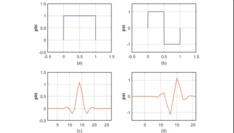
Once defined, the responsesH0(z) andG0(z), a wavelet family is designed for use in a filter bank, as both filters form the proposed filter bank in a condensed manner.
Figure 4 shows the scaling function ϕ(x) and wavelet
functionψ(x), corresponding to the designed filter bank, compared to the simplest wavelet functions, the Haar functions [17], which also have a single root atz=−1 in its analysis low-pass stage, being therefore adequate for comparison due to its simplicity of representation.
Fig-ure5 shows the zero map for the designed low-pass
fil-ters. Those simulations were performed using
MATLAB® software.
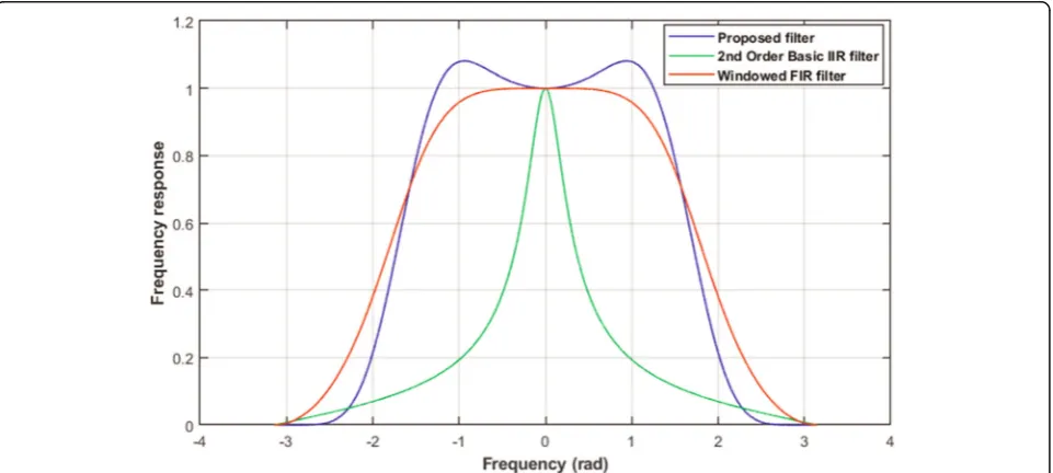
The designed synthesis low-pass or high-pass filters could be used in circuit theory, since their roots are known. This is a noticeable advantage in comparison to other filtering methods, based uniquely on the frequency response modeling. Within this method, both filter re-sponse and location of roots are performed, allowing a more flexible circuit synthesis. The frequency response
for the synthesis low-pass stage is shown in Fig.6
(nor-malized for unitary gain at Ω= 0 rad/sample), in
com-parison to a second-order continuous-time low-pass filter with cutoff frequency of 1 kHz, converted to its digital form by bilinear transformation, and, for instance, to a windowed FIR filter—a typical filter in circuit syn-thesis [36].
Figure 7 shows the frequency response in decibel for
each filter tested in Fig. 6, when compared to an ideal digital low-pass filter. These results indicate that the proposed algorithm presents better performance than
other filtering methods: at Ω=π/2 rad, the frequency
response of the proposed filter shows a stable behavior with lower attenuation, while presenting a fast conver-gence to zero at higher frequencies (Ω=π rad). Several sets of zeros were tested to factorize the product filter, being selected the one with the best signal energy bal-ance, using a few filter coefficients.
Figure 8 shows that the proposed wavelet filter
bank ensures high stop-band attenuation, despite its simpler implementations when compared to typical filter design methods [38, 39]. Finally, the filter devel-oped here is compared to other wavelet filters, in
order to validate the design method. Figure 8 shows
the frequency response of the designed synthesis low-pass filter, when compared to others obtained from alternative wavelet functions, such as the Haar and
‘orthogonal db8’ (Daubechies) ones [11, 12]. The
proposed algorithm is well suited to behave as a good window function in several signal processing applica-tions, showing a higher to accurately resolve noise and distortion components in the frequency spectrum, emphasizing the performance of the proposed model as that is measured by the behavior of the frequency response of the whole filter bank.
The present strategy shows that the concept of wavelets can be explored in the context of circuit
theory applications and becomes an additional
model to be compared to other well-established fil-ters [40–46], as it can bring out the orthogonal and the multiresolution properties of the wavelet, im-proving the efficiency of the calculations. As minor disadvantages, this technique requires a pre-process-ing of the signals to be filtered in the wavelet do-main, such as symmetric extension (a mandatory procedure in wavelet filter design [47–52]).
Fig. 5Roots of designed low-pass filters in analysis and synthesis steps. The multiplicity of roots atz=−1 for each stage (1 for analysis and 7 for synthesis) is pointed out in the figure
6 Conclusions
In summary, the use of wavelet filter banks in circuit theory allows the implementation of simple filter stages, in terms of the practical formulation involved in that task. The separation of signals into low- and high-fre-quency values is noticeably efficient, as the energy of the signals involved could be properly partitioned. Neverthe-less, the implementation of spectral factorization to wavelet filter design is adequate to build fast and simple filter circuits, in the sense that the design approach
based on the multiplicity of roots atz= −1 is shown to
be elegant and efficient, combining mathematical
consistency and good performance. Additionally, the good approximation obtained by wavelets for high-fre-quency components encourages the proposition of filter schemes in power electronics circuits, where drastic switching procedures are observed. Nevertheless, this fil-ter design method is significantly effective in obtaining a fast transition out of the passband in the frequency do-main, as well as the numerical efficiency of wavelets Fig. 7Frequency response absolute values (in decibels) for the proposed filter design, compared to a digitized continuous-time low-pass filter. The relative amplitude is varied from zero to unity
makes the method effective for fast and reliable numerical circuit simulations, despite its mathematical simplicity. The use of wavelets is also preferable in comparison to other fil-tering schemes, due to the easy time-frequency duality [48]. This shows the relevant contribution of the proposed filter, as other windowing functions do not offer enough side-lobe attenuation to be used in filtering applications. As a future development, optimization approaches could be considered for comparison, since they are not included in such analysis due to the fact they produce high computational effort for implementation, like many other IIR filter schemes.
Abbreviations
FIR: Finite impulse response; IIR: Infinite impulse response; PSNR: Peak signal-to-noise ratio
Acknowledgements Not applicable.
Authors’contributions
SRMP developed the methodology and carried the simulations. MLN and JFJ prepared the manuscript. All authors read and approved the final
manuscript.
Funding
The authors acknowledge partial funding from Brazilian agencies CAPES (Coordenação de Aperfeiçoamento de Pessoal de Nível Superior) and CNPq (Conselho Nacional de Desenvolvimento Científico e Tecnológico).
Availability of data and materials
All data were generated by the equations presented in the methods sections, which are presented in the respective figures. Data sharing is not applicable to this article.
Consent for publication Not applicable.
Competing interests
The authors declare that they have no competing interests.
Received: 14 January 2019 Accepted: 8 July 2019
References
1. A. Ambede, K.G. Smitha, A.P. Vinod, Flexible low complexity uniform and nonuniform digital filter banks with high frequency resolution for multistandard radios. IEEE Trans. Very Large Scale Integration (VLSI) Syst.
23(4), 631–641 (2015)
2. Z. Fang, S. Penglang, Construction of nonuniform DFT modulated filter banks via phase modulation. J. Electron. Inf. Technol.39(3), 2169–2174 (2017)
3. J.Z. Jiang, F. Zhou, P.L. Shui, Lifting-based design of two-channel biorthogonal graph filter bank. IET Signal Process.10(6), 670–675 (2016) 4. J.Z. Jiang, F. Zhou, P.L. Shui, S. Ouyang, Theory and design of
two-dimensional DFT modulated filter bank with arbitrary modulation and decimation matrices. Digit. Signal Process.44, 123–130 (2015)
5. D.B.H. Tay, Z.P. Lin, Design of near orthogonal graph filter banks. IEEE Signal Process. Lett.22(6), 701–704 (2015)
6. F. Zhou, P.L. Shui, J.Z. Jiang, Design of two-dimensional modified DFT modulated filter banks based on Lagrange multiplier method. J. Electron. Inf. Technol.39(5), 1261–1265 (2017)
7. Y.S. Won, K.U. Bae, N.H. Myung, Design method for bandpass filter with enhanced stopband rejection using spiral SIRs. Electron. Lett.48(17), 1067– 1068 (2012)
8. I. Daubechies, Orthonormal bases of compactly supported wavelets. Commun. Pure Appl. Math.41, 909–996 (1988)
9. J. Shen, G. Strang, The zeros of the Daubechies polynomials. Proc. Am. Math. Soc.124(12), 3819–3833 (1996)
10. C. Vonesch, T. Blu, M. Unser, Generalized Daubechies wavelet families. IEEE Trans. Signal Process.55(9), 4415–4429 (2007)
11. G. Strang,Creating and comparing wavelets(Technical Paper, Department of Mathematics, Massachusetts Institute of Technology, Cambridge, 1994), pp. 1–10
12. C. Taswell,Constraint-selected and search-optimized families of Daubechies wavelet filters computable by spectral factorization(Technical Paper, Computational Toolsmiths, Stanford, 2000)
13. M. Oishi, S. Moro, T. Matsumoto, A modified method for circuit analysis using Haar wavelet transform with adaptive resolution–For circuits with waveform with sharp convex ranges. European Conf. Circuit Theory Design (ECCTD)1(1), 299–302 (2009)
14. M. Oishi, S. Moro, T. Matsumoto, Accuracy of circuit analysis method using wavelet transform with adaptive resolutions. IEEE Region 10 Conference (TENCON)1(1), 1177–1181 (2010)
15. X.M. Xie, S.C. Chan, T.I. Yuk, Design of perfect-reconstruction nonuniform recombination filter banks with flexible rational sampling factors. IEEE Trans. Circuits Syst. I–Regular Papers52(9), 1965–1981 (2005)
16. L. Fang, W. Zhong, Q. Zhang, Design of M-channel linear-phase non-uniform filter banks with arbitrary rational sampling factors. IET Signal Process.10(2), 106–114 (2016)
17. W. Zhang, Y. Chen, Z. Dou, J. Hu,Low complexity and narrow transition band filter banks for software defined radio applications(IEEE 13th International Conference on Signal Processing (ICSP), Chengdu, 2016), pp. 1171–1175 18. B. Boashash (ed.),Time-frequency signal analysis and processing—a
comprehensive reference, 2nd edn. (Academic Press, New York, 2015) 19. P.P. Vaidyanathan, Filter banks in digital communications. IEEE Circuits Syst.
Mag.1(2), 4–25 (2001)
20. X. Chen, F.J. Harris, E. Venosa, B.D. Rao, Non-maximally decimated analysis/ synthesis filter banks: Applications in wideband digital filtering. IEEE Trans. Signal Process.62(4), 852–867 (2014)
21. S.G. Mallat, A theory for multiresolution signal decomposition: the wavelet representation. IEEE Trans. Pattern Anal. Mach. Intellig.11(7), 674–693 (1989) 22. I. Daubechies, Ten lectures on wavelets, CBMS-NSF Regional Conf. Series in
Appl. Mathematics (SIAM) 61, Philadelphia, PA, 1992
23. A. Salazar et al., Automatic credit card fraud detection based on non-linear signal processing. IEEE Int. Carnahan Conf. Security Technol. (ICCST)1(1), 207–212 (2012)
24. K. Pourvoyeur, R. Heidger, Secure ADS-B usage in ATC tracking. Tyrrhenian Int. Workshop Digit. Commun. Enhanced Surveill. Aircraft Vehicles (TIWDC/ ESAV)1(1), 35–40 (2014)
25. R. Parseh, K. Kansanen, Diversity effects in the estimation of a gauss-Markov process over a fading channel. IEEE Int. Conf. Commun. (ICC)1(1), 4644– 4649 (2014)
26. K. Sung-Eun et al., Sound transmission through the human body with digital weaver modulation (DWM) method. Ann. IEEE Syst. Conference (SysCon)1(1), 176–179 (2014)
27. M. Vetterli, C. Herley, Wavelets and filter banks: Theory and design. IEEE Trans. Signal Process.40(9), 2207–2232 (1992)
28. E.S. Filatova, D.M. Filatov, A.D. Stotckaia, G. Dubrovskiy, Time series dynamics representation model of power consumption in electric load forecasting system. IEEE NW Russia Young Researchers Electrical Electron. Eng. Conference (EIConRusNW)1(1), 175–179 (2015)
29. S.N. Mate, Identification of time-varying system with wavelet based approach using multiple wavelet basis functions. 2nd Int. Conference Electron. Commun. Syst. (ICECS)1(1), 441–446 (2015)
30. N.W.A. Lidula, R.M.M.P. Nishshanka, S.B. Wijesundara, W.L.K.D. Wijemanna, W. N.L. Weerakkody, Designing a microgrid test system for transient analysis. Moratuwa Eng. Res. Conference (MERCon)1(1), 88–93 (2015)
31. A. Cohen, I. Daubechies, B. Jawerth, P. Vial, Multiresolution analysis wavelets and fast algorithms on the interval. C. R. Acad. Sci. Paris, ser. i Math316, 417–421 (1992)
32. A.N. Akansu, R.A. Haddad,Multiresolution Signal Decomposition–Transforms, Subbands and Wavelets, 2nd edn. (Academic Press, 2001)
33. H. Youngmi, P. Hyungju, Z. Fang, Multi-D wavelet filter bank design using Quillen-Suslin theorem for Laurent polynomials. IEEE Trans. Signal Process.
62(20), 5348–5358 (2014)
34. A.I. Markushevich,Theory of functions of a complex variable, 2nd edn. (AMS Chelsea Publishing, New York, 2011)
36. L. Jian-ao, Multidimensional PR filter banks with FIR filters. Int. Conf. Commun. Circuits Syst. Proc.1, 162–166 (2006)
37. K. Avci and E. Gümüşsoy, Design of exponential window based M-channel cosine modulated filter banks, 24th Signal Processing and Communication Application Conference (SIU), Zonguldak 845–848, 2016
38. S. Dhabu, V.A. Prasad, Design of modified second-order frequency transformations based variable digital filters with large cutoff frequency range and improved transition band characteristics. IEEE Trans. Very Large Scale Integration (VLSI) Syst.24(2), 413–420 (2016)
39. Z. Songbai, Z. Lei, General synthesis method for symmetrical even-order Chebyshev bandpass filter. Microwave Conf. Proc. (APMC)1(1), 667–669 (2012) 40. R. Schaumann, H. Xiao, M.E. Van Valkenburg,Design of analog filters, 2nd
edn. (Oxford University Press, USA, 2009)
41. D. Wei, A.V. Oppenheim, Linear programming algorithms for sparse filter design. IEEE Trans. Signal Process.58(3), 1605–1617 (2010)
42. D. Wei, A.V. Oppenheim, A branch-and-bound algorithm for quadratically-constrained sparse filter design. IEEE Trans. Signal Process.61(4), 1006–1018 (2013)
43. S. Preethi, M.J. Sheela, Area efficient high and low pass filter design for DWT applications. Int. Conf. Electron. Commun. Syst. (ICECS)1, 1–5 (2014) 44. F. Ramirez-Echeverria, A. Sarr, Y.S. Shmaliy, Optimal memory for
discrete-time FIR filters in state-space. IEEE Trans. Signal Process.62, 557–561 (2014) 45. F. Ding, Y. Wang, J. Ding, Recursive least squares parameter identification
algorithms for systems with colored noise using the filtering technique and the auxiliary model. IEEE Trans. Digital Signal Process.37, 100–108 (2015) 46. Y. Liu, F. Ding, Y. Shi, An efficient hierarchical identification method for
general dual-rate sampled-data systems. Automatica50, 962–970 (2014) 47. A. Aggarwal, M. Kumar, T.K. Rawat, et al., Optimal design of 2D FIR filters
with quadrantally symmetric properties using fractional derivative constraints. Circuits Syst. Signal Process.35(6), 2213–2257 (2016) 48. N. Rashmi, G. Begum, V. Singh,ECG denoising using wavelet transform and
filters(International Conference on Wireless Communications, Signal Processing and Networking (WiSPNET), Chennai, 2017), pp. 2395–2400 49. M. Sharma, P.V. Achuth, R.B. Pachori, V.M. Gadre, A parametrization
technique to design joint time-frequency optimized discrete-time biorthogonal wavelet bases. Signal Process., 107–120 (2017)
50. X. Zhang, Design of two channel biorthogonal graph wavelet filter banks with half-B and kernels. IEICE Trans. Fundamentals Electron. Commun. Comp. Sci., 1743–1750 (2017)
51. J. Yli-Kaakinen, M. Renfors, Optimized reconfigurable fast convolution-based transmultiplexers for flexible radio access. IEEE Trans. Circuits Syst. II– Express Briefs65, 130–134 (2018)
52. J. Datta, H.P. Lin, Fast convolution filter-bank based non-orthogonal multiplexed cognitive radio (NOMCR) receiver design using cyclostationarity based FRESH filtering. Sensors18(6), 1930 (2018)
7 Publisher’s Note