warwick.ac.uk/lib-publications Manuscript version: Author’s Accepted Manuscript
The version presented in WRAP is the author’s accepted manuscript and may differ from the published version or Version of Record.
Persistent WRAP URL:
http://wrap.warwick.ac.uk/131761
How to cite:
Please refer to published version for the most recent bibliographic citation information. If a published version is known of, the repository item page linked to above, will contain details on accessing it.
Copyright and reuse:
The Warwick Research Archive Portal (WRAP) makes this work by researchers of the University of Warwick available open access under the following conditions.
Copyright © and all moral rights to the version of the paper presented here belong to the individual author(s) and/or other copyright owners. To the extent reasonable and
practicable the material made available in WRAP has been checked for eligibility before being made available.
Copies of full items can be used for personal research or study, educational, or not-for-profit purposes without prior permission or charge. Provided that the authors, title and full
bibliographic details are credited, a hyperlink and/or URL is given for the original metadata page and the content is not changed in any way.
Publisher’s statement:
Please refer to the repository item page, publisher’s statement section, for further information.
1
Abstract—This paper investigates the effects power oscillation damping (POD) controller could have on a wind turbine structural system. Most of the published work in this area has been done using relatively simple aerodynamic and structural models of a wind turbine which cannot be used to investigate the detailed interactions between electrical and mechanical components of the wind turbine. Therefore, a detailed model that combines electrical, structural and aerodynamic characteristics of a grid-connected Doubly Fed Induction Generator (DFIG) based wind turbine has been developed by adapting the NREL (National Renewable Energy Laboratory) 5MW wind turbine model within FAST (Fatigue, Aerodynamics, Structures, and Turbulence) code. This detailed model is used to evaluate the effects of POD controller on the wind turbine system. The results appear to indicate that the effects of POD control on the WT structural system are comparable or less significant as those caused by wind speed variations. Furthermore, the results also reveal that the effects of a transient three-phase short circuit fault on the WT structural system are much larger than those caused by the POD controller.
Index Terms—Wind turbine modelling, POD, DFIG, blade
edgewise vibration, Matlab/Simulink, FAST.
I. INTRODUCTION
ENEWABLE energy sources are being increasingly integrated into the grid owing to growing concerns over environmental and economic issues. Among various renewable energy technologies that are being developed, wind turbine (WT) generation system is a mainstream source of energy supply and is the fastest growing renewable energy technology in the world [1]. DFIG is one of the most popular technology for large-scale WTs due to their flexible controllability and relatively low price [2].
With the increasing penetration of wind power generation, WTs are gradually displacing conventional generating plants, and thus will influence power systems in a significant manner bringing many challenges to power system operators. Thus grid operators have been enforcing more stringent connection requirements on wind power integration and WTs are expected
M. Edrah, X. Zhao (corresponding author) and P. Qi are with the School of Engineering, University of Warwick, Coventry, CV4 7AL, U.K. (e-mail: [email protected]; [email protected]; [email protected] ). W. Hung is with WH Power Systems consultant Ltd (e-mail: ukwilliamhung @gmail.com). B. Marshall and S. Baloch are with National Grid (SO), National Grid House, Warwick, CV34 6DA, UK. (e-mail: Ben.Marshall@ nationalgrideso.com; [email protected]). A. Karcanias is with FTI Consulting, London, EC1A 4HD, UK. (e-mail: aris.karcanias@ fticonsulting .com). This work was supported by an NIA award from National Grid, UK.
to provide more ancillary services than they currently do [3]. For provision of power oscillation damping capabilitry, some WT developers are concerned that POD control could have negative impacts on their WT control and structural systems. However, this uncertainty has raised concern on more system operators regarding the need for WTs to provide power oscillation damping capability to better manage future low-frequency power oscillation risks which could lead to regional or large-scale power failure [4]. Since there is a system need and also variable speed WTs are capable of providing damping torque, the POD requirements for future WTs could be incorporated in future grid codes [3, 5].
DFIG based wind turbines are not synchronously coupled to the main grid as the power electronic converters act as an interface between the generators and the grid. Therefore, they do not directly participate in electromechanical oscillations nor do they create new power oscillation modes [6-8]. However, the steady increase of wind power integration leads to the displacement of conventional synchronous generators (SG), change of system load flow, and other topology changes. These changes could have potential influence on system oscillation modes [6, 9]. As more SGs equipped with power system stabilisers (PSSs) are replaced by WTs, the system damping capability will be in declined [10, 11]. The damping contribution from WTs will need to be made available by introducing an auxiliary POD controller into the DFIG controller [8].
Over the past few years, considerable research has been done on POD capability of DFIGs by using active or reactive power modulations [4, 7-19]. In [7, 10, 12, 15-17, 19], the auxiliary damping signal produced by the POD controller is attached to the active power reference signal of the active power control loop within rotor side converter (RSC). The RSC controls the active and reactive power outputs of the DFIG independently. Study results indicate that the active power modulation of DFIG is a powerful tool to introduce additional damping for power system oscillations. Moreover, It is shown in [10, 12, 15-17] that DFIG with POD can contribute to the POD much more effectively than the SG with a PSS. In contrast, in [11, 13, 18], the auxiliary damping signal produced by the POD controller is attached to the reactive power reference of the reactive power control loop within the RSC. The results indicate that the reactive power modulation can improve damping of power oscillations. However, it was reported [20] that the use of reactive power modulation can deteriorate the DFIG stator dynamics. As offshore wind farms are often remotely connected and the altering of their terminal
Effects of POD Control on a DFIG Wind
Turbine Structural System
Mohamed Edrah,Xiaowei Zhao
, William Hung, Pengyuan Qi, Benjamin Marshall,Aris Karcanias, Shurooque Baloch
2 voltage under weak connections with the grid can cause voltage oscillations and instability problems. The results of [21] indicated that active power modulation is generally much more effective than its reactive counterpart. Although the active power modulation is more effective in modulationg the generator electromagnetic torque, it may increase the stress on the DFIG drivetrain and decrease the lifespan of the mechanical system [20].
The active power modulation may have impact on the turbine’s mechanical parts via the electromagnetic torque variations. These may excite the mechanical vibrations of the WT blades, tower, and drivetrain, leading to mechanical failure. Such interactions of the WT mechanical structure with DFIG control system have not been adequately investigated.
For instance, previous research on POD capability of DFIG WTs has been done using relatively simple mechanical and aerodynamic models that neglect a number of important characteristics from a mechanical representation perspective. The work was focused mainly on the electrical aspect and this could lead to inaccurate interaction dynamics between electrical and mechanical components during the activation of POD control. In this paper, a more detailed model including electrical, structural and aerodynamic characteristics of a grid-connected DFIG-WT is presented to evaluate the impacts that POD controller could have on the WT structural system. The developed model was tested by time-domain simulations to examine the interactions between electrical and mechanical parts when providing POD control. The natural vibration modes of the DFIG-WT structural system are identified and evaluated under different operating conditions. The obtained results are compared with those caused by a grid fault. The results offer a deep understanding of the inherent electro-mechanical dynamics of the DFIG-WT during either normal operation or with POD control.
The structure of the paper is as follows: Section II describes the development of the grid and DFIG-WT models including the mechanical parts of the WT. Section III is about the POD control design. Section IV shows the simulation results of the developed models. Finally, Section V summarises the key findings of the investigation.
II. MODEL DEVELOPMENT
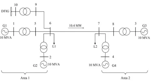
A detailed model of grid-connected DFIG-WT that includes electrical, mechanical and aerodynamic characteristics is developed in this section by combining two simulation codes. National Renewable Energy Laboratory’s (NREL’s) Fatigue, Aerodynamics, Structures, and Turbulence (FAST) simulation tool [22] is used to provide detailed simulation of the aerodynamics and mechanical aspects of WT whereas Matlab/Simulink simulation package [23] is used to simulate DFIG, converters, collector systems, and grid aspects. The developed DFIG-WT model was integrated into a four-machine two-area test system as shown in Fig. 1. An oscillation was introduced between the two areas and a POD controller was implemented in the DFIG-WT model to improve the oscillation damping between the two areas.
A. Two-Area System Model
[image:3.612.317.560.232.367.2]The studies were carried out on the two-area benchmark power test system shown in Fig. 1. The test system is based on the well-known two-area benchmark system which is widely used to study the low-frequency electromechanical oscillations in power systems [24]. It is reduced to a smaller equivalent system to match the rating of 5 MW WT model in this study. Each area of the reduced system is equipped with two identical round rotor SGs rated at 10 MVA modelled using Matlab/Simulink. Each machine is equipped with a turbine governor and an excitation control system. However, none of the SGs has a PSS for a more straightforward assessment. The load is split between the two areas in such a way that area 1 is exporting power to area 2.
Fig. 1 Two-area test system configuration with DFIG-WT.
B. Modelling of DFIG-WT system
The typical simulation structure of DFIG-WT is shown in Fig. 2. The DFIG-WT consists of a WT with a DFIG including a wound rotor induction generator and back-to-back converters. The stator of the induction generator is directly connected to the utility grid whereas the rotor is connected via slip rings to the back-to-back converters namely, RSC and grid side converter (GSC). With the back-to-back converters, DFIG can operate over a wide range of rotational speeds at constant voltage and frequency. Therefore, active power flow magnitude and direction between the grid and the rotor of the induction generator is controlled. The rotor of the induction generator is mechanically connected to the WT over a mechanical shaft system, which consists of a high-speed shaft, a gearbox, and a low-speed shaft.
1) Mechanical parts of WT Model
3 structure, flapwise and edgewise blades deflections, tower fore-aft and side-to-side bending and drivetrain torsion can be examined.
FAST uses equations of motion to calculate the degree of freedom. The active forces 𝑭𝑟 and inertia forces 𝑭𝑟 balance is achieved during motion as following [26]:
0
r r
F + F = (1)
Where r is the index of rth degree of freedom
The beam axis displacement and beam mode shapes of the flexible structure can be defined by:
1
( , ) a
( ) ( )
am a
u z t =
z q t
=
(2), ( 1, 2.... )
( ) a h h
( )
a z =
c
z
and a= m
(3)Where qa(t) is the beam generalised coordinates, ca,h is the
interpolating polynomial coefficients, and h(z) is the shape
functions.
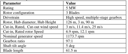
[image:4.612.51.298.57.186.2]FAST software is a complex tool that can be used to analyse a range of onshore and offshore WTs and it is adequate to simulate many complex situations concerning WT performance. FAST-V8 [27], which is the most recent version, is used to conduct the required simulations within this paper. The mechanical model in FAST is coupled with an aerodynamic model based on the Blade Element Momentum (BEM) theory [28]. In this paper, FAST is used to simulate the NREL 5-MW offshore baseline WT which is a representative of a typical utility-scale WT. It is a conventional horizontal-axis, three-bladed, variable speed WT. Table 1 lists its main specifications, more details can be found in [29].
Table 1 Main specifications of NREL 5-MW baseline WT.
Parameter Value
Rating 5 MW Rotor configuration 3 Blades
Drivetrain High speed, multiple-stage gearbox Rotor, Hub diameter, Hub Height 126 m, 3 m, 90 m
Cut-in, Rated, Cut-out wind speed 3 m/s, 11.4 m/s, 25 m/s Cut-in, Rated rotor Speed 6.9 rpm, 12.1 rpm Nominal generator speed 1173.7 rpm Gearbox ratio 97:1 Shaft tilt angle 5 deg Blade length 61.5 m
Blade, Rotor, Tower masses 17,740 kg, 110,000 kg, 347,460 kg Hub inertia about low-speed shaft 115,926 kg.m2
Maximum blade pitch angle rate 8 deg/s
FAST simulation tool reads mechanical system parameters of NREL 5-MW offshore baseline WT from specific input files and then creates output files. FAST can be used to exchange data with Simulink introducing great flexibility for electrical system and control implementation. This enables users to implement an electrical system and advanced turbine control design in Simulink block while the aerodynamics and structural parts are modelled in FAST.
2) Modelling of DFIG controllers
Although FAST is very popular to model and analyse WT’s mechanical parts, the generator representation in FAST is very simple. In this paper, the FAST is modified and interfaced with Matlab/Simulink to include a detailed and well-presented generator model in Matlab/Simulink. This allows examining the loadings of different WT components under both grid transients and/or wind turbulence conditions. Thus, the impacts of the turbine control system on its mechanical components can be observed. The interface between FAST and Simulink is shown in Fig. 2.
[image:4.612.313.566.423.565.2]The DFIG-WTs can be fully controlled by using the back-to-back converters. The RSC can independently control the generated active and reactive power while the GSC is mainly used to maintain the converters DC link voltage within the limit. Both converters are modelled as current controlled voltage source converters.
Fig. 3 Control scheme of the RSC and POD (dashed blue lines).
In Fig. 3, the vector control scheme of the RSC is shown where the stator active power Ps and reactive power Qs are
independently controlled by the outer control loops. The measured active and reactive power are compared with reference signals obtained by maximum power point tracking (MPPT) curve and reactive power set point respectively. The generated error signals are passed through proportional integral (PI) controllers to form two output signals i*
qr and i*dr of the dq
axes current components which are referred to active and reactive power control loop respectively. These two signals are compared to the measured current signals iqrand idr in the dq
axes and passed through a PI controller to form two voltage
dr V qr V * qr
i
Vqr1dr
i
* dri
Vdr1 [image:4.612.47.307.630.741.2]s P 2 dr V 2 qr V qr
i
+ - - + + + - + - RSC * s Q + r MPPT PWM VdcFig. 2 General simulation structure of DFIG-WT with controls.
AC Grid
Gear box
DFIG
Grid Side Control
Rg & Lg
GSC RSC
AC
Crowbar
Ps & Qs
Pr
Qr
RotorSideControl
Wind Turbine Control
β
C
DC AC
Wind
Pg
4 signals vqr1 and vdr1 respectively. The formed two voltage
signals are then compensated by the corresponding cross-coupling voltage in dq axes to form the dq voltage signals
vqrand vdr respectively. These signals are then connected to a
pulse width modulation (PWM) to create signals for the IGBTs gate control.
In a similar way, the GSC can be modelled to regulate dc link voltage and the reactive power that is exchanged between the GSC and the grid [13, 30].
III. PODCONTROLDESIGN
The aim of this section is to develop a POD controller for DFIG-WT to damp low-frequency power oscillations between 0.1-2 Hz by adding an additional signal to the active power control loop of DFIG as shown in Fig. 3 with blue dashed lines. The considered POD is based on the conventional lead-lag controller which is the most widely implemented in industrial application due to its robustness, simple design and low cost [31]. The conventional lead-lag controller was chosen because of its simple design and it can easily satisfy the requirement of implementation in practice. The transfer function of the considered POD can be expressed by (4).
3 1
2 4
1 1
1 1 1
pod w
w
out in
ST ST ST
ST ST T
K
S
POD + + POD
+ + +
=
(4)The input signal to the PODin is the active power deviation
between the measured tie-line active power and the steady state value. The generated signal is passed to a stabiliser gain Kpod
which is used to determine the amount of damping introduced by the POD. A washout filter has a time constant Tw (s) that
only allows a certain range of frequency to pass unchanged and eliminate steady state variations. A second-order lead-lag compensator with time constants T1-T4 (s) is used to create the
required phase compensation between the input and the output signals. In addition, a POD limiter is used to ensure that the output signal is under the control limits, which has been taken as ±15% of nominal power in our conducted studies.
In order to enhance the damping of the poorly damped low-frequency power oscillations, critical oscillatory modes have to be modified by the POD. This can be done by choosing optimal parameters for T1-T4 and Kpod to guarantee optimal POD
performance.
Various methods could be used to obtain optimal settings of POD parameters. In this work, the particle swarm optimization (PSO) algorithm is used to search the optimal parameters of the proposed POD controller based on time-domain simulation of the developed nonlinear DFIG-WT and grid models. PSO is a widely used optimization method in power systems [32, 33]. As the power system oscillations are reflected in the deviations in the transferred active power between the two areas of the test system, the PSO is used to minimize active power deviation between the measured tie-line active power and the steady state value. The optimal parameters of the POD are given in (2).
10 1 0.4427 1 1.0813
1 10 1 0.2827 1 0.17478
0.06
out in
S S S
S S S
POD POD
+
= + +
+ +
(2)These parameters are obtained under a steady wind speed condition of 14 m/s with an export of about 10.4 MW from area 1 to area 2.
IV. SIMULATION RESULTS AND DISCUSSION
The time-domain simulation is based on the grid-connected DFIG-WT model developed in Section II to evaluate the performance of POD controller and its effects on the WT structural parts such as blades, tower, and drivetrain. The simulation results are obtained with a steady (14 m/s) and variable (covers above and below rated value) wind speed scenarios. The results prior to 50 seconds are omitted to allow the starting up of the wind turbine model.
A. POD controller performance
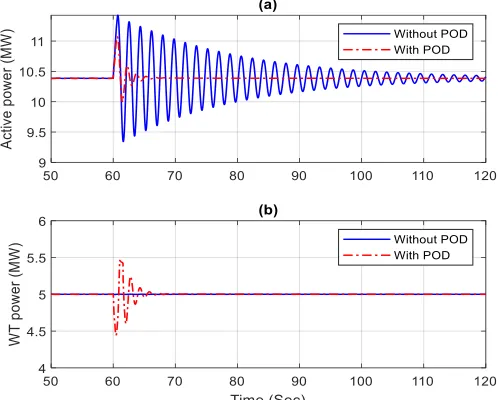
To evaluate the POD control performance, a grid disturbance, which can lead to power oscillation between the two areas, is applied on machine G3 under the following operating conditions: wind speed of 14 m/s, export of 10.4 MW from area 1 to area 2. The grid-connected DFIG-WT model is injected with a step-voltage on generator G3 in Fig. 1. The voltage increases temporarily for 300 ms from 1 pu to 1.05 pu at 60s leading to a power system oscillation of 0.6 Hz on the tie line between area 1 and area 2 as shown in Fig. 4 (a) where the power system oscillations of the two cases (without and with POD) are plotted. In the case without POD, the WT maintains its rated output power at 5 MW during the entire simulation period as shown in Fig. 4 (b). However, in the POD control case, the active power output is modulated by the POD via the active power control loop. The difference in generated active power between the two cases (without and with POD) occurs only when the POD controller starts to damp the power transfer oscillation between the two areas at 60 s as shown in Fig. 4 (b).
[image:5.612.314.563.507.707.2]5 The time-domain simulation clearly shows that the inter-area power oscillation can be damped quickly if the DFIG-WT is equipped with the proposed POD as shown by the red dashed line in Fig. 4 (a). This shows the effectiveness of the designed POD controller in damping out the inter-area power oscillation. The power system oscillation reaches steady state value in less than 10 s. Moreover, it can be observed that the amount of injected energy during the active time of POD controller is almost zero as the kinetic energy from DFIG-WT rotating mass is utilized as storage from which damping power is derived. This indicates that the operator of the WT with POD control will not lose energy and hence revenue during the operational time of the POD controller.
B. Effects of POD on the WT’s mechanical performance
with steady wind speed
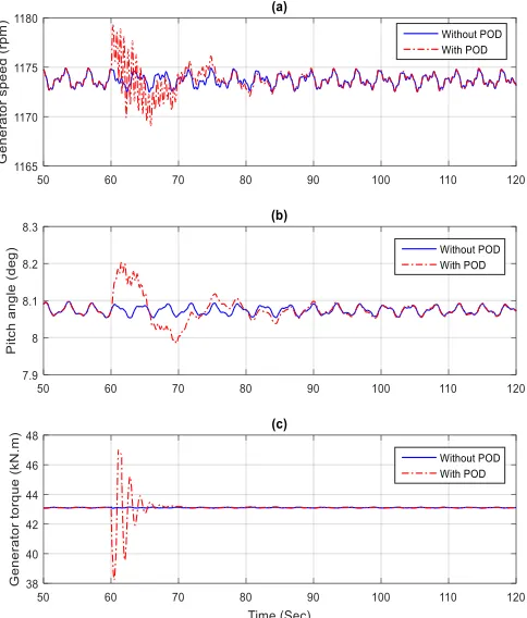
In this section, the effects of POD on the WT generator, blades, tower, and drivetrain performances are evaluated under the following operating conditions: wind speed of 14 m/s, export of 10.4 MW from area 1 to area 2, and a temporary voltage step-up of 0.5% at 60 s for 300 ms at the terminal of G3. Fig. 5 shows the transient response of NREL 5-MW WT model without and with POD control. As can be seen in Fig. 5 (a), the generator speed is maintained at its rated value when there is no POD controller. To damp power oscillation, the NREL model decreases its output power at the beginning of the power oscillation leading to a rapid decrease in the generator torque, and thus, the generator speed increases, where the pitch controller tries to keep that constant. The change in generator torque is shown in Fig. 5 (c) which only starts to vary after 60 s when the POD controller is activated to damp power oscillation. Moreover, as the WT is operating in a wind speed region above the rated wind speed, the pitch angle is activated with 8.1 deg to maintain the generator speed at its rated value as shown in Fig. 5 (b). The pitch angle increases at 60 s to control the increase in rotor speed only in the case with POD control.
After the power oscillation is damped, the control schemes of the DFIG operate as normal and the generator speed, pitch angle and generator torque reach their steady-state operation point in about 10 s. It is worth mentioning that the generator speed fluctuates around the rated speed as the generator rotational speed is dictated by the overall system dynamics including the effects of aerodynamic torque, blade vibrations, hub inertia, generator inertia, and drivetrain dynamics.
The blade 1 flapwise and edgewise tips deflections along with tower fore-aft and side-to-side displacements are shown in Fig. 6 for the two cases with and without POD control. It can be observed that the blade 1 flapwise and edgewise tip deflections vibrate at 0.2 Hz which is known as 1P frequency as shown in Fig. 6 (a, b). The 0.2 Hz frequency component is due to the rotation of the turbine blades at a speed of 12.1 rpm. A similar kind of vibration is expected to be found on blades 2 and 3. Therefore, the effects of three blades vibrations produce a periodic reduction in mechanical torque at a frequency of 0.6 Hz called the 3P frequency. From Fig. 6 (a, b), it can be observed that the POD has a negligible effect on the blade 1 edgewise tip deflections. However, the blade 1 flapwise tip
[image:6.612.316.558.114.398.2]deflection is affected slightly for a short period after the POD controller is activated. The sudden changes in the generator electromagnetic torque can therefore slightly excite the blades flapwise tip deflections.
Fig. 5 Dynamic response of WT (a) rotor speed in rpm, (b) pitch angle in deg, (c) generator torque in kN.m.
[image:6.612.315.560.455.659.2]6 The simulation results also show the tower is oscillating at two similar frequencies of 0.272 Hz for fore-aft and side-to-side as shown in Fig. 6 (c, d). The tower vibration frequencies are caused by WT aerodynamics and blade pitching in combination with generator torque variation and inertia. Fig. 6 (c, d) shows that these frequencies can marginally be excited by the electrical side of the DFIG-WT. The POD control can have some but insignificant effects on both fore-aft and side-to-side displacements of the tower. Although the tower fore-aft vibration experiences larger amplitude than tower side-to-side, it is damped faster. The (insignificant) side-to-side vibration persists for the entire simulation time with the same magnitude and frequency.
From Fig. 5 and Fig. 6 it can be concluded that the POD can have some minor effects on the mechanical behaviour of WT. The rapid change in generator torque can develop a considerable generator speed variation, which in turn causes mechanical vibrations on the turbine blades and tower.
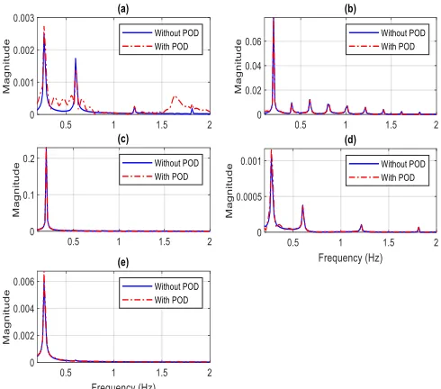
The Fast Fourier Transform (FFT) method is applied to generator speed, flapwise and edgewise tips deflections, fore-aft and side-to-side displacements, to analyse their spectrums as shown in Fig. 7. The frequency domain analysis of the generator speed reveals that there are several frequencies associated with the generator speed as shown in Fig. 7 (a). Some frequency components come from other parts of the WT structure. The frequency of 0.27 Hz is due to tower fore-aft and side-to-side frequency, which has been identified previously. The frequency of 0.6 Hz is due to the effects of three blades frequency (3P). Other frequency components are harmonic of rotating speed (6P, 9P etc). Equipping the WT with a POD controller can excite some of the existing natural frequencies. The first frequency of the generator speed is slightly excited. The frequency domain analysis also shows the natural frequencies of the turbine blade 1 which comes from 1P frequency which was identified previously and its harmonics (2P, 3P, etc). The WT blades flapwise tip deflections are slightly excited whereas the blades edgewise tip deflections have not been changed or excited by the POD controller as shown in Fig. 7 (b, c). The tower fore-aft and side-to-side natural frequencies have been slightly affected by the POD controller as shown in Fig. 7 (d, e). The magnitude of the first tower frequencies in the fore-aft and side-to-side planes are slightly larger when the WT is equipped with POD controller.
Fig. 8 shows the drivetrain acceleration, twist angle of the shaft and frequency domain analysis of drivetrain acceleration for the cases with and without POD control. The drivetrain acceleration shows how POD control may excite the drivetrain vibration. During normal operation without POD controller, the acceleration of drivetrain fluctuates around zero. However, as soon as the POD is activated, the acceleration of the drivetrain increases to about 2 deg/sec2 as shown in Fig. 8 (a). The
[image:7.612.314.559.50.266.2]frequency domain analysis of the drivetrain acceleration reveals that there are several frequencies associated with the drivetrain acceleration as shown in Fig. 8 (b). The frequency components of drivetrain acceleration largely agreed with the frequency components of generator speed shown in Fig. 7.
Fig. 7 Frequency domain analysis of the WT (a) generator speed, (b) flapwise tip deflection, (c) edgewise tip deflections, (d) tower fore-aft displacements, and (e) tower side-to-side displacements.
Fig. 8 (a) Drivetrain acceleration and (b) frequency domain analysis of drivetrain acceleration for the two cases (with and without POD).
C. Effects of POD on the WT’s mechanical performance
with variable wind speed.
[image:7.612.313.563.314.445.2]7
Fig. 9 Dynamic response of WT (a) wind speed in m/s, (b) pitch angle in deg, (c): generator torque in N.m.
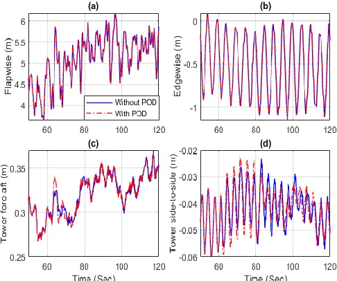
The blade 1 tip deflections along with tower fore-aft and side-to-side displacements are shown in Fig. 10 for the cases with and without POD control. From Fig. 10 (a), it can be observed that the POD has a negligible effect on the blade 1 flapwise tip deflection when compared to the steady wind speed case. This is because of the changes caused by the wind speed variation are larger than that are caused by the POD. However, similar results to the steady wind speed case have been obtained for the edgewise tip deflections of the turbine blades as the POD has a negligible effect on edgewise tip deflections as shown in Fig. 10 (b). Fig. 10 (c, d) shows the tower fore-aft and side-to-side displacements with and without POD with variable wind speed. Consistent with the steady wind speed results, the POD control has some but insignificant effects on both fore-aft and side-to-side displacements of the tower. The tower fore-aft vibration experiences slightly larger vibration amplitude than tower side-to-side, whereas the fore-aft vibrations are damped faster.
The effect of POD control on the drivetrain with variable wind speed is shown in Fig. 11. The drivetrain acceleration changes due to the POD action are shown in Fig. 11 at around 60 s is about 2 deg/s2 as compared to 1 deg/s2 in the case
without POD. At 78 s, the drivetrain acceleration rises to 3 deg/s2 due to the change in the wind speed. The drivetrain
acceleration changes following the activation of the POD are therefore similar or less than that caused by wind variations. The changes in the magnitude of the drivetrain acceleration that is caused by POD are less than that caused by the wind speed variations.
[image:8.612.53.293.52.232.2]Fig. 10 DFIG-WT (a) blade 1 flapwise tip deflections, (b) edgewise tip deflections, (c) tower fore-aft displacements, (d) tower side-to-side displacements with and without POD control in the case of variable wind speed.
Fig. 11 Drivetrain acceleration for the variable wind speed.
In general, the simulation results under the variable wind speed show that the POD control has some effects on the WT structural system, but the scale of the observed changes are comparable or less significant as those caused by wind speed variations that WTs encounter daily.
D. Effects of three-phase short circuit on the WT’s
mechanical performance.
[image:8.612.317.538.321.432.2]8
Fig. 12 DFIG-WT (a) terminal voltage, (b) pitch angle, (c) generator speed and (d) generator power during steady state condition and a three-phase short circuit.
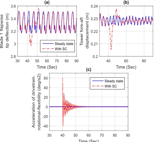
Similar transient changes are observed in flapwise tip deflections of the WT, tower fore-aft displacements, and drivetrain acceleration and all of these transient changes are considerably larger than that caused by the POD as shown in Fig. 13. As the drivetrain rotational flexibility is highly influenced by the differences between mechanical and electrical torques, the fault creates large fluctuations in the drivetrain twisting angle and acceleration for about 20 s as shown in Fig. 13 (c). The scale of these fluctuations is about 20 times higher than that caused by the POD. The results of three-phase short circuit analysis show that the effects of three-phase short circuit fault have on the DFIG-WT structural system are much higher than those caused by the POD control as shown in Fig. 6.
Fig. 13 DFIG-WT (a) blade 1 flapwise tip deflections, (b) tower fore-aft displacements, and (c) drivetrain acceleration in the case of steady state condition and a three-phase short circuit.
V. CONCLUSIONS
In this paper, the effects of POD controller on the WT structural system were simulated using a detailed model that combines electrical, structural and aerodynamic characteristics of a grid-connected utility-scale wind turbine. The POD control for active power modulation was designed and tuned by the widely adopted PSO algorithm. The results showed that incorporating DFIG-WT with a POD controller within the active power control loop can have effective damping on the power system oscillations. However, the POD controller also appeared to have a small influence on the WT structural system. This was arising from the POD induced changes on the generator electromagnetic torque which in turn influenced the WT drivetrain dynamics and hence the blades and the tower of the WT.
In addition, the inherent vibration frequencies of the WT structural system were identified and compared with those arising from additional POD interactions. The results showed that the POD slightly excited some of the natural frequencies of the WT structural system. For instance, the first drivetrain frequency could be excited by POD implementation but its magnitude and duration appears to be insignificant. In general, the simulation results indicated that the effects of POD control on the WT structural system are comparable or less significant than those caused by wind speed variations that WTs encountered daily. Moreover, the effects of a three-phase short circuit fault on the WT structural system are much larger than those caused by the POD control. In a similar way, the obtained results within this paper could be applied to offshore PMSG wind turbines, but this will be further investigated.
The results within this paper are obtained with wind speed around the rated value and low-damping power oscillation, which are the worst-case scenarios. In practice, the effects of the POD on the DFIG-WT system would therefore be expected to be lower than that observed in this study.
REFERENCES
[1] G. W. E. Council, "Global wind statistics 2016," in "Global Wind Report,"2016,Available: http://gwec.net/publications/global-wind- report-2/global-wind-report-2016/.
[2] R. Sitharthan, C. Sundarabalan, K. Devabalaji, S. K. Nataraj, and M. Karthikeyan, "Improved fault ride through capability of DFIG-wind turbines using customized dynamic voltage restorer," Sustainable Cities and Society, 2018.
[3] A. Etxegarai, P. Eguia, E. Torres, A. Iturregi, and V. Valverde, "Review of grid connection requirements for generation assets in weak power grids," Renewable and Sustainable Energy Reviews, vol. 41, pp. 1501-1514, 2015.
[4] T. K. Chau, S. S. Yu, T. L. Fernando, H. H.-C. Iu, and M. Small, "A novel control strategy of DFIG wind turbines in complex power systems for enhancement of primary frequency response and LFOD," IEEE
Transactions on Power Systems, vol. 33, no. 2, pp. 1811-1823, 2018.
[5] M. Mohseni and S. M. Islam, "Review of international grid codes for wind power integration: Diversity, technology and a case for global standard,"
Renewable and Sustainable Energy Reviews, vol. 16, no. 6, pp.
3876-3890, 2012.
[6] D. Gautam, V. Vittal, and T. Harbour, "Impact of increased penetration of DFIG-based wind turbine generators on transient and small signal stability of power systems," IEEE transactions on power systems, vol. 24, no. 3, pp. 1426-1434, 2009.
[7] G. Tsourakis, B. M. Nomikos, and C. D. Vournas, "Contribution of Doubly Fed Wind Generators to Oscillation Damping," Energy
[image:9.612.51.298.481.709.2]9
[8] J. L. Domínguez-García, O. Gomis-Bellmunt, F. D. Bianchi, and A. Sumper, "Power oscillation damping supported by wind power: A review," Renewable and Sustainable Energy Reviews, vol. 16, no. 7, pp. 4994-5006, 2012.
[9] W. Du, J. Bi, J. Cao, and H. Wang, "A method to examine the impact of grid connection of the DFIGs on power system electromechanical oscillation modes," IEEE Transactions on Power Systems, vol. 31, no. 5, pp. 3775-3784, 2016.
[10] D. Gautam, V. Vittal, R. Ayyanar, and T. Harbour, "Supplementary control for damping power oscillations due to increased penetration of doubly fed induction generators in large power systems," in Power
Systems Conference and Exposition (PSCE), 2011 IEEE/PES, 2011, pp.
1-6.
[11] M. Edrah, K. L. Lo, and O. Anaya-Lara, "Reactive power control of DFIG wind turbines for power oscillation damping under a wide range of operating conditions," IET Generation, Transmission & Distribution, vol. 10, no. 15, pp. 3777-3785, 2016.
[12] M. Edrah, K. L. Lo, A. Elansari, and O. Anaya-Lara, "Power oscillation damping capabilities of doubly fed wind generators," in Power
Engineering Conference (UPEC), 2014 49th International Universities,
2014, pp. 1-6: IEEE.
[13] M. Edrah, K. L. Lo, and O. Anaya-Lara, "Impacts of high penetration of DFIG wind turbines on rotor angle stability of power systems," IEEE
Transactions on Sustainable Energy, vol. 6, no. 3, pp. 759-766, 2015.
[14] K. Liao, Z. He, Y. Xu, G. Chen, Z. Y. Dong, and K. P. Wong, "A sliding mode based damping control of DFIG for interarea power oscillations,"
IEEE Transactions on Sustainable Energy, vol. 8, no. 1, pp. 258-267, 2017.
[15] Y. Mishra, S. Mishra, M. Tripathy, N. Senroy, and Z. Y. Dong, "Improving Stability of a DFIG-Based Wind Power System With Tuned Damping Controller," Energy Conversion, IEEE Transactions on, vol. 24, no. 3, pp. 650-660, 2009.
[16] Z. Miao, L. Fan, D. Osborn, and S. Yuvarajan, "Control of DFIG-based wind generation to improve interarea oscillation damping," Energy
Conversion, IEEE Transactions on, vol. 24, no. 2, pp. 415-422, 2009.
[17] F. M. Hughes, O. Anaya-Lara, N. Jenkins, and G. Strbac, "A power system stabilizer for DFIG-based wind generation," Power Systems, IEEE
Transactions on, vol. 21, no. 2, pp. 763-772, 2006.
[18] K. Liao, Y. Xu, Z. He, and Z. Y. Dong, "Second-Order Sliding Mode Based PQ Coordinated Modulation of DFIGs Against Interarea Oscillations," IEEE Transactions on Power Systems, vol. 32, no. 6, pp. 4978-4980, 2017.
[19] M. Singh, A. J. Allen, E. Muljadi, V. Gevorgian, Y. Zhang, and S. Santoso, "Interarea oscillation damping controls for wind power plants,"
IEEE Transactions on sustainable energy, vol. 6, no. 3, pp. 967-975, 2015.
[20] F. Lingling, Y. Haiping, and M. Zhixin, "On Active/Reactive Power Modulation of DFIG-Based Wind Generation for Interarea Oscillation Damping," Energy Conversion, IEEE Transactions on, vol. 26, no. 2, pp. 513-521, 2011.
[21] S.-Y. Ruan, G.-J. Li, B.-T. Ooi, and Y.-Z. J. E. P. S. R. Sun, "Power system damping from energy function analysis implemented by voltage-source-converter stations," vol. 78, no. 8, pp. 1353-1360, 2008. [22] J. M. Jonkman and M. L. Buhl Jr, "FAST User's Guide-Updated August
2005," National Renewable Energy Laboratory (NREL), Golden, CO.2005.
[23] R. E. P. N. F. T. S. CENTURY, "Renewables 2016 global status report-Annual Reporting on Renewables: Ten years of excellence," 2016. [24] P. Kundur, N. J. Balu, and M. G. Lauby, Power system stability and
control. McGraw-hill New York, 1994.
[25] G. P. Prajapat, N. Senroy, and I. N. Kar, "Wind Turbine Structural Modeling Consideration for Dynamic Studies of DFIG Based System,"
IEEE Transactions on Sustainable Energy, vol. 8, no. 4, pp. 1463-1472,
2017.
[26] A. Cetrini, F. Cianetti, F. Castellani, and D. J. P. S. I. Astolfi, "Dynamic modeling of wind turbines. How to model flexibility into multibody modelling," vol. 12, pp. 87-101, 2018.
[27] NWTC. ( Accessed December-2017). Last modified 27-July-2016. Available: https://nwtc.nrel.gov/FAST8
[28] M. O. Hansen, Aerodynamics of wind turbines. Routledge, 2015. [29] B. J. Jonkman, "TurbSim user's guide: Version 1.50," National
Renewable Energy Lab.(NREL), Golden, CO (United States)2009. [30] Q. Wei, G. K. Venayagamoorthy, and R. G. Harley, "Real-Time
Implementation of a STATCOM on a Wind Farm Equipped With Doubly Fed Induction Generators," Industry Applications, IEEE Transactions on,
vol. 45, no. 1, pp. 98-107, 2009.
[31] M. A. Abido, "A novel approach to conventional power system stabilizer design using tabu search," International Journal of Electrical Power &
Energy Systems, vol. 21, no. 6, pp. 443-454, 1999.
[32] M. Abido, "Optimal design of power-system stabilizers using particle swarm optimization," IEEE transactions on energy conversion, vol. 17, no. 3, pp. 406-413, 2002.
[33] J. Kennedy, "Swarm intelligence," in Handbook of nature-inspired and
innovative computing: Springer, 2006, pp. 187-219.
[34] B. J. Jonkman and M. L. Buhl Jr, "TurbSim user's guide," National Renewable Energy Lab.(NREL), Golden, CO (United States)2006.
Mohamed Edrah received the B.Sc. (Hons) from Altahadi University, Libya, and MSc (Distinction) from Heriot-Watt University, UK and the Ph.D. degree from the University of Strathclyde, UK, in 1996, 2010, and 2017, respectively, all in electrical engineering. He has extensive industrial experience in the field of electrical power system engineering including power system modelling, simulation, analysis, planning, and control. He was a Senior Power Systems and Consulting Engineer with GECOL, Libya, from 1999 to 2013. In 2017, he joined the School of Engineering, University of Warwick, UK, where he is currently a Research Fellow. His research interests include power system analysis, and operations, renewable generation integration and control, and smart grids.
Xiaowei Zhao is Professor of Control Engineering at the School of Engineering, University of Warwick. He obtained his PhD degree in Control Theory from Imperial College London. After that, he worked as a postdoctoral researcher at the University of Oxford for three years before joining Warwick in 2013. His research interests include (1) control of wind/tidal turbines/farms; (2) grid integration of renewable energy; (3) microgrid; (4) control of fluid-structure interaction with applications to large and flexible wind turbines, highly flexible aircraft, and long-span suspension bridges; (5) control of coupled infinite-dimensional systems.
10 Pengyuan Qi received his B.S. degree in automation from University of Science and Technology Beijing, China, in 2013, and the M.S. degree in control science and engineering from Beijing University of Aeronautics and Astronautics, China, in 2016. He is currently pursuing the Ph.D. degree at the University of Warwick, Coventry, UK. His research interests include modeling and control of highly flexible structures, e.g. HALE UAVs, wind turbines, etc.
Ben Marshall joined National Grid in 1996 and has across over 22 years of Power System analysis roles across both the Transmission Owner and Electricity System Operator areas of the company designed and developed a range of network reinforcements, control systems, operational strategies and assessment tools. He has designed and implemented several significant changes to the operation and design of the network, for example the accommodation of large HVDC systems, and the development of the infrastructure of central London. He has had extensive experience in the modelling and design of complex control systems associated with the delivery of dynamic voltage and frequency stability, and inputted in previous innovation in this area, for example the VISOR project, from a National Grid perspective. For the past 4 years, Ben has forfilled the role of Technical Specialist with the Electricity System Operators’ System Performance team, delivering analysis and supporting investigation of a range of operability areas, including supporting National Grids investigations into new faster frequency response capability under the EFCC project. He contributes to a number of external industry workgroups, this includes chairing the Virtual Synchronous Machine Grid Code Expert Group and being active across areas of new European Grid Code implementation.
Aris Karcanias is the co-lead of the Global Clean Energy Practice at FTI Consulting. He has a technical engineering background, with extensive experience leading board-level strategy, technology development, and M&A for leading utilities, manufacturers, and investors. Aris specialises in clean energy systems, their integration, and the redesign of the future energy system.