1.
2.
3.
4.
5.
6.
7.
GENERAL
Features.
PHYSICAL DESCRIPTION •
Front Panel Rear Panel
Card Cage -- S-IOO Bus. S-IOO Bus Cards •
Power Supply fvt:>dule • Diskette Drive.
Winchester Drive.
FUNCTIONAL DESCRIPTION •
SPECIFICATIONS •
5505 CCJt1PUTER
MAINTENANCE
TABLE OF CONTENTS
OPERATION AND INSTALLATION •
Unpacking Ac Line • Options •
Set Up and Turn On.
MAINTENANCE.
Customer Support Service.
Repacking and Returning Material. Diagnostics •
Fault Location.
Power Supply fvt:>dule Voltages and Adjustment Removing Assemblies •
REFERENCES •
S-100 Bus •
.,
Schematics and Replaceable Parts.
OEM EquiJ;ment •
DYNABYTE - Page 1
3
3
6
7
7
.10
.11
.14 .14 .14
.15
.21
.27
.27
.28 .28 .28
.35
.35 .35
.37 .37
.38 .39
.44
ILLUSTRATIONS
.
. . .
• 5Table 1-1 -- 5505 Computer, Models • • •
Figure 2-1 -- 5505 Computer, Front Panel
. . .
• 5Table 2-1 -- 5505 Computer, Front Panel Controls and Indicators. • • • • 6
Figure 2-2 -- 5505 Computer, Rear Panel. • • • • • • • • • • • • 8
Table 2-2 -- 5505 Computer, Rear Panel Controls and Connectors. • 8
Table 2-3 -- 5505 Computer, Interior Major Assemblies • • •
Figure 3-1 -- 5505 Computer Functional Block Diagram •
Table 4-1 -- 5505 Computer Functional Specifications •
. .
Figure 5-1 -- Central Processing Unit, Option Switch Settings.
Figure 5-2 -- 641< Random Access Memory, Option Switch Settings •
.13
.17
.22
• .31
• • • 32
Figure 5-3 -- Disk Controller, Option Switch Settings • • • • • •
. .
.33.34
.37 Figure 5-4 -- Auxiliary Disk Controller, Option Switch Settings ••
Figure 6-1 -- Dynabyte Identification Plate. • • • • • • • • •
Figure 6-2 -- Power Supply Module Voltage Test Points, BS1 • • • •
Table 6-1 -- Troubleshooting Chart • • • • • • •
Table 7-1 -- Dynabyte 8-100 Bus Pin Assignments. • •
Figure 7-1 -- 5505 Computer Chassis Wiring Diagram • •
Table 7-2 --. 5505 Computer Replaceable Parts List.
.
.
. .
. .
.
.
• •• 38 • • • • • 42• .45
• .51
5505 Technical Manual 404512
1. GENERAL
1.01 This manual provides a physical and functional description and
the operating theory necessary for effective installation and field service of the 5505 Computer.
Features
1.02 The 5505 Computer, illustrated on the title page, is supplied
indivi-dually or as a system component to a larger Dynabyte computer system. Its features include the following:
• Z-80 microprocessor operating at 4 MHz.
• Two serial, software-programmable 110 to 76,800 baud ports. Each of
the ports' data lines may be configured to an RS-232C level or 20
rnA
current loop data communication line interface.
• One parallel port wi th full handshaking logic.
• Double Density Diskette Controller.
• Mini~inchester Controller.
• Built-in Diskette Drive in single-sided or double-sided
configuration (see Table 1-1).
• Built-in Mini~inchester Drive (see Table 1-1).
• Ten internal timers.
• Sixteen priortized vectored interrupts.
• A real-time clock.
• 64K of Random Access Memory. Optional memory to 400K bytes can also
be provided with multiple memory cards.
• The power supply module features pre regulation to minimize
operational problems from brown outs and line voltage surges.
• Efficient cooling of the 5505 S-IOO cards and power supply is assured
by a 4-5/8 inch axial fan furnishing air through the chassis and exhausted out through the rear panel.
• The backplane is shielded and fully socketed for 12 S-IOO card
positions.
• Heavy' duty metal construction.
• The front panel switches POWER and RESET-HALT are illuminated.
• A line fuse is provided for ac line protection.
• Each internal subassembly is modular and is unit-replaceable for ease in servicing.
• Each 5505 carries a lBO-day warranty on parts and labor from the date
of shipment from Dynabyte.
5505 Technical Manual 404512
Table 1-1 -- 5505 ~omputer, Models
5505 - Al 5505 - Bl 5505 - Cl
Floppy Disk Drive
Surfaces 1 2 2
Unfonnatted Capacity 500K 1000K 1000K
Fonnatted Capacity 315K 655K 655K
Winchester Hard Disk Drive
Surfaces 4 4 6
Unfonnatted Capacity 6. 4MB 10. 67MB 16MB
Formatted Capacity 5. 32MB
a.9MB
13.4MB1.03 Dynabyte maintains hardware and software compatibility with Dynabyte
S-100 .cards used in the Dynabyte S-IOO Bus only. S-IOO I/O cards, e.g.,
modems, clocks, and parallel ports from other manufacturers will be compatible with the Dynabyte S-100 Bus in most cases. Contact Dynabyte for specific applications.
4
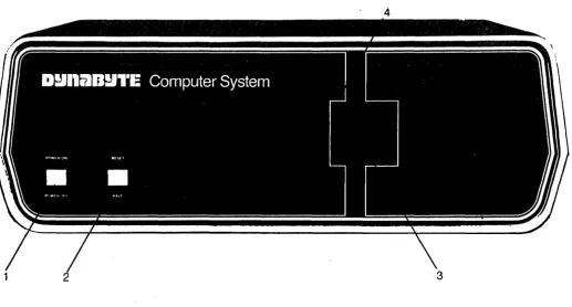
Figure 2-1 -- 5505' Computer, Front Panel 807129
[image:6.615.75.546.103.324.2] [image:6.615.41.558.437.714.2]Key
1
2
3
4
Table 2-1 -- 5505 Computer, Front Panel Controls and Indicators
Element
POWER ON OFF
SWitch and Indicator
RESET Switch and HALT Indicator
Diskette Drive
Diskette Drive Select Indicator
Function
Applies the ac line to the 5505 Computer and the ac power receptacle on the rear panel. Refer to Figure 2-2, Key 3. The indicator lights When +8 Vdc is available from the power supply.
Momentarily grounds the S-IOO Reset line
generating a Power On Clear (POC) sequence:
(1) CPU Program Counter is reset, (2) Disk Contoller is reset.
When the indicator is lit, the CPU has stopped at a Z-80 HLT (76H) instruction in the
program.
Provides for reading and writing onto 5.25" double and single sided floppy Diskettes for permanent storage of programs and data files.
Lit when Disk Controller selects drive for a read or write operation.
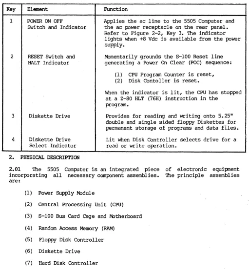
2. PHYSICAL DESCRIPTION
2.01 The 5505 Computer is an integrated piece
incorporating all necessary component assemblies. are:
(1) Power Supply Module
(2) Central Processing Unit (CPU)
(3) S-lOO Bus Card Cage and Motherboard
(4) Random Access Memory (RAM)
(5) Floppy Disk Controller
(6 ) Diskette Drive
(7) Hard Disk Controller
(8) Winchester Hard Disk Drive
Some of the optional assemblies are:
(9) Octaport (an eight-port seria~ I/O).
(10) Additional Random Access Memory (RAM).
[image:7.615.49.561.95.652.2]5505 Technical Manual 404512
Details on these individual assemblies, as well as their schematic diagrams and ,replaceable parts lists, are funished under separate cover as individual technical manuals. These assemblies have been enclosed in an exceptionally compact package measuring 52 em x 47 em x 18 em (20.5 in. x 18.5 in. x 7 in.) weighing 25 kg (about 55 lbs.).
2.02 The 5505 draws nominally 400 VA of 115 Vac, 60 Hz commercial power. It
may be factory optioned for operation from a 230 Vac, 50 Hz line.
2.03 The 5505 is designed to operate efficiently in an environment with an
ambient temperature range from 10 to 35 degrees Centrigrade (50 to 95
degrees Farenheit) and with a relative humidity from 20 to 80 percent.
2.04 Figures 2-1 and 2-2 provide number key callouts of all components
located on the front, rear and interior of the 5505. Associated Tables 2-1 through 2-3 provide a cross reference for each callout, identifying the respective part as to function, description and/or designation.
Front Panel
2.05 Refer to Figure 2-1 for the description Which follows. The 5505
Computer Front Panel has only two operating controls with which the user should be concerned.
(1) The POWER ON OFF Switch turns the computer on and off. The switch also
connects the ac line power to a convenience receptacle on the rear panel. The switch also contains an indicator which lights when there is an output
from the internal +8 Vdc power supply.
(2) The RESET Switch is used to restart the computer if it should become
locked up due to a software or hardware malfunction. Operating the RESET Switch causes the S-IOO Reset Line, Pin 75, to be active low. The Reset
Line is an input to the Power On Clear (POC) circuits and resets the CPU
Program Counter, Disk Controller, etc. Then the CPU initiates a reboot by jumping to a starting address appropriate for the user's system. The switch also contains an indicator, which, when lit, indicates the CPU has read a Halt (HLT) instruction and has stopped.
The right half of the front panel contains the 5.25 inch diskette storage unit.
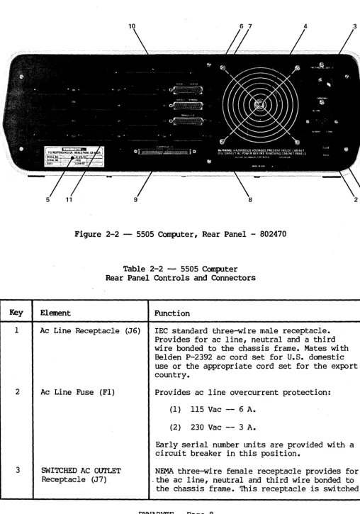
Rear Panel
2.06 Figure 2-2 illustrates the Rear Panel of the 5505 Computer. Table 2-2
tabulates and describes each of the rear panel elements. Ac line and computer
Input Output (I/O) connections are through the rear panel. At the right, the
ac line is connected through an IEC connector. This permits the 5505 to be
connected domestically to 115 Vac, 60 Hz with a National Electrical
Manufacturers Association (NEMA) cord set or internationally with a cord set appropriate for that country. A line fuse provides protection for the 5505 and equipment powered from the ac convenience receptacle above.
Key
1
2
3
Figure 2-2 -- 5505 Computer, Rear Panel - 802470
Table 2-2 -- 5505 Computer Rear Panel Controls and Connectors
Element Function
Ac Line Receptacle (J6) lEe standard three-wire male receptacle.
Provides for ac line, neutral and a third wire bonded to the chassis frame. Mates with Belden P-2392 ac cord set for U.S. domestic use or the appropriate cord set for the export country.
Ac Line Fuse (Fl) Provides ac line overcurrent protection:
(1 ) 115 Vac -- 6 A.
(2) 230 Vac -- 3 A.
Early serial number units are provided with a circuit breaker in this position.
SWITCHED AC OUTLET N~ three-wire female receptacle provides for
Receptacle (J7) . the ac line, neutral and third wire bonded to
[image:9.629.47.556.57.782.2]5505 Technical Manual 404Sl2
4
5
6
7
8
9
10
11
Axial Fan
Dynabyte Identification Plate
SERIAL 1 PRINTER Port Receptacle
SERIAL 2 TERMINAL Port Receptacle
PARALLEL I/O Port Receptacle
FLOPPY DISK I/O Receptacle
Hard Disk I/O Access Hole and Clamp
I/O Port Connector Area
by the POWER ON Switch on the front panel -refer to Figure 2-1, Key 1 - and is protected by fuse, Key 2, above.
Provides for drawing heat from the power
supply module and internal heat dissipating pc
assemblies.
Furnishes the model and serial number neces-sary for warranty service. Refer to Figure 6-1.
O8-2S-S connector. Optionally EIA RS-232C or
20 rnA current interface. Connection point for
the EIA cable to the Serial Printer.
D8-2S-S connector. Optionally EIA RS-232C or
20 rnA current interface. Connection point for
the EIA cable to the Video Tenninal.
DB-2S-S connector. Eight-bit parallel I/O connection point to 2S-conductor cable to a parallel printer.
SO-conductor ribbon connector. Provides a connection point for the cable to the Dynabyte 5010 Dual Diskette Storage.
Furnishes a hole and clamp for the cable to the Dynabyte S012 Cartridge Module Drive or SOlI or 5013 Winchester Drive.
Provides positions for O8-2S-S connectors. Figure 2-2 illustrates connectors for:
(1) Three ports from the CPU
(2) Up to 16 ports from;~p to two
Octaport cards. '<
CAUTION
Power consumption from the ac convenience" receptacle is limited to 200 V A.
2.07 A four-inch fan draws heat dissipated internally out of the rear
panel. Air is drawn into the 5S05 cabinet through louvers provided in the bottom of the cabinet.
IMPORTANT
Install the 5505 Computer so as not to obstruct the air flow through the louvers in the bottom of the cabinet and allow a three-inch clearance from the rear of the fan.
Desk-type system cabinets supplied from Dynabyte are designed to assure constant air flow through the computer.
2.08 Several mass storage devices can be used with the 5505. The rear panel
furnishes connector access for these devices.
(1) A fifty-pin ribbon cable connector provides for disk I/O signals,
control signals and status signals to a Dynabyte 5010 Dual Diskette Storage Unit.
(2) disk unit.
A rectangular hole provides access for a multi-wire ribbon cable for I/O signals, control and status to a Dynabyte 5011 or 5013 storage
2.09 Sixteen positions are provided on the rear panel for.08-25-S
connectors and are used for I/O signals to the system peripheral devices such as:
(1) Serial Printers
(2) Video Terminals
(3) Parallel I/O Printer
(4) Acoustical Coupler or Modems
Each installation will vary depending upon the selection of peripheral devices and the applications programs in use. Three I/O ports are furnished as part of
the
cpu.
These are shown connected to the rear panel illustrated in Figure2-2. In applications requiring additional ports, a Quadraport or an Octaport may be installed into the S-lOO Bus and interconected to the rear panel. Both the front and rear panels are secured to their respective bezel by 6-32 Kep nuts. Each bezel is secured to the base plate by 6-32 screws. Both panel and bezel may be easily removed for servicing or installation of additional I/O ports in the field.
Card Cage - 5-100 Bus
2.10 The card cage furnishes a rigid support structure for the S-IOO Bus
cards when they are inserted into the S-IOO Bus. The Motherboard PC Assembly
contains 12 S-IOO Bus receptacles or jacks, Jl through J12. Each jack has. 100
separate pins. The actual bus consists of 100 parallel traces on the pc board
5505 Technical Manual 404512
2.11 The 8-100 Bus lines are described by function in Part 3 of this
manual. Physically they make up five groups:
(1) Power and common lines. These are connected to the power supply module
discussed in 2.17. 8ix lines.
(2) Address lines. 16 lines.
(3) Data In and Out lines. 16 lines.
(4) Control 8ignal lines. 40 lines.
(5) Dynabyte Reserved lines. 22 lines.
The Motherboard PC Assembly also contains a few discrete components which make up the Halt Detector. The Halt Detector and Reset line are connected to the front panel by a four-conductor receptacle, J13, connected to plug, P13,
mounted at the front edge of the Motherboard PC Assembly.
5-100 Bus Cards
2~12 Dynabyte 5-100 Bus cards are pc assemblies normally measuring 5 x 10
inches. A laO-pin edge connector mates with the 8-100 Bus connector on the
motherboard. This connector is offset by 5/8 inch from the card centerline, i.e., an 8-100 Bus card cannot be inserted into a jack backwards.
2.13 Dynabyte 8-100 Bus cards may have one or more on-board regulators for
regulating and distributing the dc power supply voltages from the bus to the logical elements on the card.
NOTE
An
5-100 Bus card should never be insertedor removed from the bus when the ac 1 ine
power is on.
2.14 A solder mask is applied to the component and non-component sides of
the pc boards when it is manufactured and before it is loaded with components.
This mask covers all surfaces except:
(1) The 100 gold-plated fingers of the edge connectors,
(2) Each of the plated-through holes.
The solder mask assures there will be no bridges between traces. The soldering operation can then only take place. at a hole where normally solder joins a component lead and a pad.
2.15 Dynabyte 8-100 Bus cards usually provide sockets for most multi-lead
active devices to facilitate fault location and servicing.
2.16 Options for Dynabyte 8-100 cards are provided by three m~thods:
(1) Dual-In-Line packaged (DIP) switches of one to nine poles, 8PST, are
normally used in functions which may have to be set to the user's individual
installation.
(2) Bare wire straps are soldered into the pc board for options Which are
installed at the factory. These are not to be changed in the field except by instructions from Dynabyte Customer Support or When specified in the individual Dynabyte S-100 Bus Card Technical Manual.
IMPORTANT
Never change the settings of an Option Switch without referring to the Option Switch Tables in the individual
Dynabyte 8-100 Bus Card Technical Manual.
(3) Instructions are written into a programmable read-only memory (PROM) at
the Dynabyte factory, resulting in a read-only memory (ROM). In some
applications a ROM can be phantomed" into a desired range of addressed RAM.
Phantoming means a memory segment can replace another under program control.
When the 5505 is set to POWER ON or RESET is operated, the CPU jumps to the I
starting address of the disk controller ROM. The ROM boot instructions are
overlaid at the common address location. These instructions are for the CPU to read Track 0, Sector 1 from Drive A. This particular operation is called the ROM Boot. Track 0, Sector 1 contains additional instructions which are loaded into-RAM and executed. These instuctions cause the CPU to read the Dynabyte Disk Operating System from the diskette or disk. This second operation is called the Disk Boot. The ROM is then switched out.
NOTE
Dynabyte ROMs are individually marked with a Dynabyte part number. The part number represents an individual program for a specific equipment configuration. The ROM part numbers are tabulated for various equipment configurations in the specific 8-100 Bus Card Technical Manual.
Changes in options of this type are made by exchanging the particular ROM. ROMs are only available from Dynabyte.
2.17 Dynabyte S-lOO Bus cards carry a distinctive White silkscreened
marking on the component side of the pc assembly.
(1) The card name and part number. This facilitates board identification
and referencing for reordering, servicing and referencing the appropriate Dynabyte S-lOO Card Technical Manual, schematic or replaceable parts list.
(2) Component reference designators are marked When practical. They
facilitate locating the individual part on a schematic or parts list.
Most Dynabyte PC assemblies derive the major component reference designators
from a row-column matrix silkscreened onto the pc board. For example, rows
5505 Technical Manual 404512
circuit located in the upper left corner is Al and the one located in the lower right corner is 018.
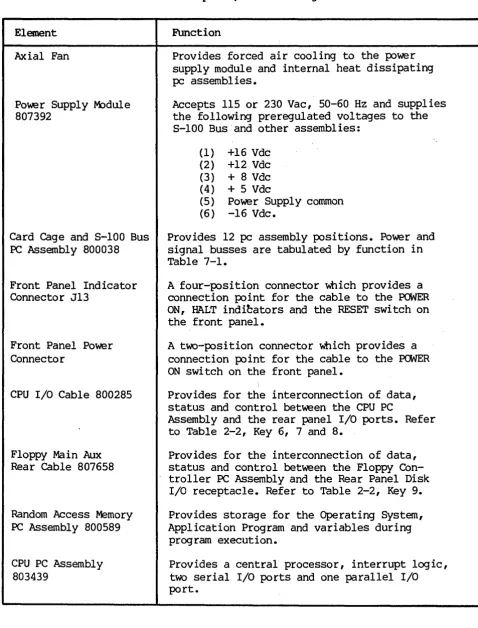
Table 2-3 -- 5505 Computer, Interior Major Assemblies
Element
Axial Fan
Power Supply M:>dule
807392
Card Cage and S-IOO Bus
PC Assembly 800038
Front Panel Indicator
Connector J13
Front Panel Power Connector
CPU I/O Cable 800285
Floppy Ma in Aux
Rear Cable 807658
Random Access Memory
PC Assembly 800589
CPU PC Assembly
803439
FUnction
Provides forced air cooling to the power supply module and internal heat dissipating
pc assemblies.
Accepts 115 or 230 Vac, 50-60 Hz and supplies
the following preregulated voltages to the S-IOO Bus and other assemblies:
(1) +16 Vdc
(2) +12 Vdc
(3) + 8 Vdc
(4) + 5 Vdc
(5) Power Supply cornmon
(6) -16 Vdc.
Provides 12 pc assembly positions. Power and
signal busses are tabulated by function in
Table 7-1.
A four-position connector Which provides a
connection point for the cable to the POWER
ON, HALT indi~ators and the RESET switch on
the front panel.
A two-position connector Which provides a connection point for the cable to the POWER ON switch on the front panel.
Provides for the interconnection of data, status and control between the CPU PC
Assembly and the rear panel I/O ports. Refer
to Table 2-2, Key 6, 7 and 8.
Provides for the interconnection of data, status and control between the Floppy
Con-troller PC Assembly and the Rear Panel Disk
I/O receptacle. Refer to Table 2-2, Key 9.
Provides storage for the Operating System, Application Program and variables during program execution.
Provides a central processor, interrupt logic, two serial I/O ports and one parallel I/O port.
[image:14.615.70.549.134.763.2]Disk Controller PC Assembly 807525
Winchester Controller PC Assembly 807677
Cabinet Louvers
Auxiliary Controller 807506
5.25 Floppy Drive to Aux Cable 807639
Data Separator Card 807243
Provides the logic, status registers and ROM bootstrap to support the Dynabyte diskette drive.
Provides the logic, status registers and data buffer to support the hard disk drive.
Provides air inlets for drawing air into the cabinet for ventilation.
Provides the specialized electrical functions for:
(1) 5.25 inch diskette drives
(2) 8.00 inch diskette drives
option strapping allows the Disk Controller, Key 10 above, to work with both types of media.
Provides for supplying I/O signals to the drive module.
Converts data in a disk format to data readable by the Winchester Controller.
2.18 Input/Output (I/O) Signals not affecting the S-lOO Bus are transferred
over special multi-pin connectors normally located at the top of the pc
assembly. Cable harnesses which mate with these connectors are normally made up of flat multi-pair or flat twisted multi-pair cable.
Power Supply Module
2.19 The power supply module is located at the rear of the 5505 cabinet
between the card cage and the rear panel. The power supply operates on 115 or 230 Vac, 50 or 60 Hz line, optioned internally by straps. It utilizes a phase-controlled regulator to provide ac line and load regulation. The supply operates at relatively high efficiency and utilizes a minimum of components resulting in high reliability. The ac chassis wiring to the power supply module includes an EMI filter to minimize radiation of power supply switching transients over the ac line.
Diskette Drive
2.20 The Diskette Drive is mounted at the right front of the chassis. Power
for this module is furnished from the 5505 power supply module.
Winchester Drive
2.21 The Winchester Hard Disk is mounted at the right front of the chassis.
5505 Technical Manual 404512
3. FUNCTIONAL DESCRIPTION
3.01 Part 3 will furnish the user with an overview of the 5505 Computer and
the 5-100 Bus. Detailed information on individual Dynabyte 5-100 cards is provided in its technical manual.
NOTE
An
*
suffix to a signal name indicateslogical NOT and active low.
3.02 Figure.3-1 illustrates the 5505 computer in block diagram. It should
be used in conjunction with the schematic diagrams in Part 7 to familiarize
the user with the circuits. The 5505 Computer chassis can be divided into four logical sections:
(1) Ope~ational Controls
(2) Power Supply M:>dule
(3) 5-100 Bus
(4) 5.25 inch Diskette Drive
(5) 5.25 inch Winchester Hard Disk Drive
3.03 Two operation controls are provided on the 5505 Computer.
(1) The POWER switch applies ac line voltage to the fan, ac convenience
receptacle and power supply module. The POWER ON indicator is lit \IA1en the power supply module outputs nominally +8 Vdc.
(2) The RE5ET switch pulls the Reset line, Pin 75, of the 5-100 Bus low to
initiate a restart of the CPU, etc. The reset switch housing contains a
lamp and indicates a halt when lit. A Halt Detector is part of the 5-100 Motherboard PC Assembly. This detector monitors the HLTA line, Pin 48. When this status line goes high, a HLT instruction has been executed. The HALT indicator is lit.
3.04 The Power SUpply Module converts ac line voltage to low dc voltages for
the 5-100 Bus and monitoring circuits. It provides regulation against ac line fluctuations and load variations of the 5-100 Bus. The output voltages are nominally:
(1) +16 Vdc
(2) +12 Vdc
(3) + 8 Vdc
(4) + 5 Vdc
(5) -16 Vdc.
One adjustment, R2 on the M:>dulator PC Assembly and part of the power supply module, is used to set the +8 Vdc supply output voltage. The other voltages are nominal and track the +8 Vdc. Refer to Figure 6-2 for the tolerance range.
3.05 Regulation is provided by a triac modulating the ac line applied to
the low voltage power transformer. The +8 Vdc output line is monitored and a feedback loop is used to control the conduction of the triac resulting in phase-controlled regulation.
3.06 The +16, +8 and -16 output voltages are passively filtered. Ripple on
the +8 Vdc line is 0.3 to 1 Volt. The +5 and +12 voltages are set and controlled by three-terminal regulators. These two voltages power the diskette and hard disk drives.
3.07 The S-IOO Bus system consists of a set of signal lines used to carry
all information, interface messages and device-dependent messages among interconnected devices.
3.08 The bus structure is organized into seven sets of signal lines: Refer
to Table 7-1 for descriptions of the following.
(1 ) Data Lines
(2) Address Lines
(3) Status Bus
(4) Control Output
(5) Control Input Bus
(6 ) Vectored Interrupt Bus
t'Ij
...,.
Ul c:..,
CD w I ~ U1 U1~
0 U16;
()~
~
[%] r1'
I (1)
..,
'"0
g
OJ I.Q CD 0 ~ rt-...J
...,.
0 ::J OJ ~ to ~ 0 0 ~ tj
...,.
~..,
~ I/O Ports---Central Processing Unit Random Access Memory
/ --""
r
/11 1 /
/ ~al 2 Term1!!ill,'\.
Interconnect 1IIIIIr-1---/"7"1'-1---t-1~/
.... / ~allell@h
---~+-~~~~----~~---~---~J_--~--/ Dynabyte S-100 Bus
~~LThlIl / I Line -600 VA
'I 1 /1 '\.1 1 LI "I J6 Neutral
60 Hz Reference
Line Filter and Power Supply
1---
+16 Vdc1---
+12 Vdc 1 - - - I I t - - -+8 Vdc1---+----+5 Vdc
1 - - - ; - - - - -16 Vdc
{[wTICHEoAcOUTLITI , - _ _ _ _ _ I
l~i~=;O;VA _ , , _
~I ~~~~--~---+---~I -vO
:J
w I®rnE~I
FANSL _-_
_-=-=-
~i Neutral ION OFFI
1 S2
I
1
~
Data ~,
Separator
Aux
~ ~O Controller
/
/ ~ V3lt
AI'
Slt II V
Winchester / 34
Drive
~,
1,
5%
Halt Diskette
Detector Drive
NOTE
In and Out References are in respect to the CPU.
3.09 The data bus consists of 16 lines grouped as two unidirectional 8-bit
busses for byte operations.
(I) Data output appears on the data output bus DOO - D07. D07 is the most
significant bit.
(2) Data input appears on the data input bus DIO - DI7. DI7 is the most
significant bit.
3.10 The address bus consists of 16 signal lines used to select a specific
location in memory or a specific input/output device for communications during the current bus cycle. The memory address bus consists of 16 lines specifying 1 of 64K memory locations. These 16 lines are named AO through A15, Where A15 is the most significant bit. The I/O device address bus consists of lines, AO through A7, specifying 1 of 256 I/O devices, with A7 used as the most significant bit. Address lines A15 - A8 are used as an I/O address modifier in specific cases, i.e., the Octaport.
3.11 The status bus consists of nine lines that identify the nature of the
bus cycle in progress and qualify the nature of the address on the address
bus. The mnemonics for status lines always begin with a lo~r case sand
consist of:
(I) Memory Read -- sMEMR
(2) Op-Code Fetch -- sMl
(3) Input -- sINP
(4) Output - sOUT
(5) Write Cycle -- sWO*
(6) Interrupt Acknowledge -- sINTA
(7) Halt Acknowledge -- sHLTA
(8) Memory Request -- sMREQ*
(9 ) Memory Refresh -- sRFSH*
3.12 The lines of the control output bus dete~ine the timing and movement
of data during any bus cycle. The mnemonics for the control output lines
always begin with a lo~r case p. The four lines are:
(I) pSYNC*, which indicates the start of a new bus cycle.
(2) pDBIN, a generalized read strobe that gates data from an addressed
5505 Technical Manual 404512
(3) pWR*, a generalized write strobe that writes data from the data bus
into an addressed slave.
(4) pHLDA, the hold acknowledge signal that indicates to the highest
priority temporary master that the pennanent master is relinquishing control of the bus.
3.13 The five lines of the control input bus allow bus slaves to
synchronize the operations of bus masters with conditions internal to the bus slave, e.g., data not ready, and to request operations of the permanent master, e.g., interrupt or hold. The five control input lines are:
(1) ROY (2) XRDY
(3) INT*
(4) NMI*
(5) HOLD*
The ready lines are used by bus slaves to synchronize bus masters to the response speed of the slave. Thus cycles are suspended and wait states inserted until both ready lines are asserted. The ROY line is the general ready line for bus slaves. It is specified as an open collector line. The XRDY line is a special ready line used by test devices to stop and single-step bus masters. It is not specified as an open collector line and should not be used by other bus slaves since a bus conflict may exist.
3.14 . The two interrupt lines INT* and NMI* are. used to request service from
the perma~ent b~s master. The INT* line may be masked off by the bus master,
~sually VIa an Internal software geqeratiQn. If the bus ma~ter accePts the
Interrupt request on the INT* lIne, It may respond WIth an Interrupt acknowledge bus cycle accepting vectoring information from the data bus.
3.15 The NMI* line is a nonmaskable interrupt request line, that is, it may
not be masked off by the bus master. Accepting an interrupt on the NMI* line
will not generate an interrupt acknowledge bus cycle. An interrupt request on
the INT* line is asserted as a level, that is, the line is asserted until
interrupt service is received. An interrupt request on the NMI* line, on the
other hand, is asserted as a negative-going edge, since no interrupt
acknowledge cycle will be generated. Both lines are specified as
open-collector lines.
3.16 The hold request line, HOLD * , is used by temporary bus masters to
request control of the bus from the permanent bus master to prevent temporary masters from gaining bus control. The HOLD* line is specified as an open collector line and may only be asserted at certain times.
3.17 The eight lines of the vectored interrupt bus are used in conjunction
with the generalized vectored interrupt request, INT*, to arbitrate among eight levels of interrupt request priorities. The eight lines of the vectored
interrupt bus are VIO* through VI7*, where VIO* is considered the highest
priority interrupt. The vectored interrupt lines should be implemented as
levels; that is, they should be held active until service is received.
3.18 Power in the Dynabyte 8-100 Bus systems is distributed to bus devices
as unregulated voltages. A total of six bus lines is used:
(1) +8 Volts, 2 lines
(2) +16 Volts, 1 line
(3) -16 Volts, 1 line
(4) Power supply common, 2 lines.
3.19 The system clock, 4 MHZ PHASE 2, is generated by the
cpu.
The controltiming for all bus cycles must be derived from this clock. This signal is never transferred during a bus exchange operation.
3.20 Another line, called CLOCK, is specified as a 2 MHz, 0.5 percent
tolerance, signal with no relationship to any other bus signal. It is used by counters, timers, baud-rate generators, etc.
3.21 8ystem reset functions are divided into two lines:
(1) RE8ET* is an open collector input line that requests a Power On Clear
(POC) •
(2) POC*, power on clear is active on PCMER ON and when requested by
RE8ET*, is specified as having a minimum active period of 10 ms.
3.22 The memory write strobe, MWRT, is generated by the permanent bus
master and is defined as:
MWRT = pWR • sOUT* (logic equation)
3.23 Another line, PHANIDM*, is provided for overlaying bus slaves at a
common address location. When this line is activated, phantom bus slaves are enabled and nonnal bus slaves are disabled. This line is specified as an open-collector line.
3.24 The remaining lines are designated as Dynabyte reserved and for use in
future 8-100 card and system designs.
3.25 The Diskette Drive provides the 5505 Computer with internal mass
storage for application programs and data files. Each diskette will store 655K
formatted bytes in the double-sided mode. An Auxiliary Controller is part of
the drive module. The Auxiliary Controller allows the Disk Controller, installed in the 8-100 Bus, to be used with double density 5.25 inch diskettes. Disk Controller I/O signals are supplied to a 50-pin receptacle on the rear panel for additional mass storage, e.g., 5010.
3.26 The Winchester Hard Disk Drive provides the 5505 Computer with
5505 Technical Manual 404512
4. SPECIFICATIONS
4.01,. Part 4 furnishes the user with information for shipping and
installation and should be used to establish acceptance tests if they are
performed. Minor deviations from the specifications tabulated in Table 4-1
which do not affect the 5505 Computer are excluded from the Dynabyte Warranty.
4.02 The functional specifications of the 5505 Computer are determined by:
(1) The Dynabyte Disk Operating System and the particular application
program running, i.e., the software.
(2) The specific Dynabyte S-lOO cards installed in the bus, i.e., the
hardware.
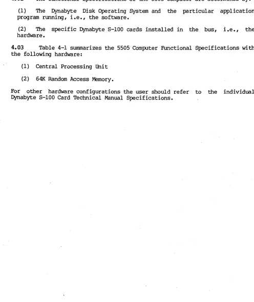
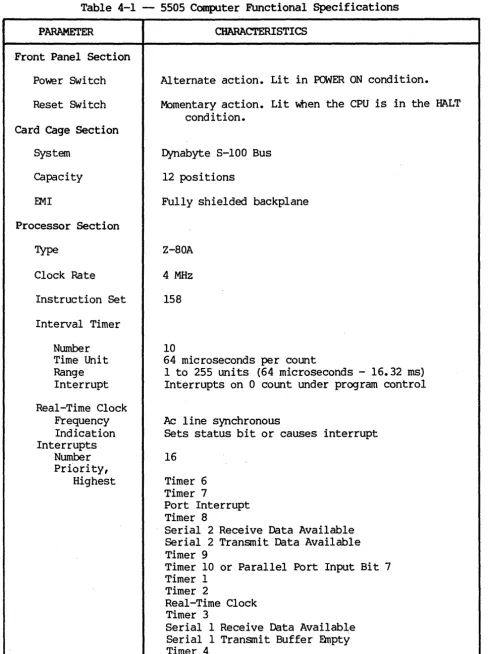
4.03 Table 4-1 summarizes the 5505 Computer Functional Specifications with
the following hardware:
(1) Central Processing Unit
(2) 641< Random Access Memory.
For other hardware configurations the user should refer to the individual Dynabyte 5-100 Card Technical Manual Specifications.
[image:22.617.54.550.163.752.2]Table 4-1 - 5505 Computer Functional Specifications
PARAMETER
Front Panel Section
Power Switch
Reset Switch
Card Cage Section
System
Capacity
EMI
Processor Section
Type
Clock Rate
Instruction Set
Interval Timer
Number
Time Unit Range Interrupt
Real-Time Clock Frequency Indication Interrupts
Number
Prfority, Highest
CHARACTERISTICS
Alternate action. Lit in POWER ON condition.
Momentary action. Lit when the CPU is in the HALT condition.
Dynabyte S-IOO Bus
12 positions
Fully shielded backplane
Z-80A
4 MHz
158
10
64 microseconds per count
1 to 255 units (64 microseconds - 16.32 ms) Interrupts on 0 count under program control
Ac line synchronous
Sets status bit or causes interrupt
16
Timer 6 Timer 7
Port Interrupt Timer 8
Serial 2 Receive Data Available Serial 2 Transmit Data Available Timer 9
Timer 10 or Parallel Port Input Bit 7 Timer 1
Timer 2
Real-Time Clock Timer 3
[image:23.618.61.549.63.716.2]5505 Technical Manual
PARAMETER
Priority, Lowest
CHARACTERISTICS
Timer 5
Levels of Interrupt 2 Masking
Levell Level 2
Masks all interrupts
Individual masking of interrupts
Off Card Interrupts One maskable One unmaskable
Input/OUtput Section
2
404512
Serial Ports
Rates 110, 150, 300, 880, 1200, 2400, 4800, 9600, 19,200,
38,400, 76,800 baud
Rate Selection Connector
Data In Data Out Signal Common Data In
Data Out
Parallel Port Input
Input Ready Flag Input Sense Output
OUtput Strobe OUtput Flags Connector
Memory Section
Random Access Mdress
Size
Type
Ojcle Time
Optional Size
Floppy Diskette Drive
Surfaces
Tracks Per Surface
Software control O8-25-S
EIA RS-232C EIA RS-232C EIA RS-232C
20 rna current loop 20 rna current loop
1
8 bits
Edge triggered
1 bit
8 bits 1 bit
2
OB-25-S
16 bits
65,536 bytes (64K) Dynamic
400 ns
Bank swi tching 400K bytes maximum
M)DEL 5505-Al
1
77
DYNABYTE - Page 23
M:>DELS 5505-81, -Cl
2
PARAMETER
Media
Unformatted Capacity
Track Surface
Total Capacity
Formatted Capacity
Sectors Per Track Sector Size
Surface
Total Capacity
Transfer Rate
Average Latency
Head Load
Access Time
Track to Track Settling
Average Access
Track Density
Spindle Speed Variation
Recording Density
Flux Density
Encoding Method
Reliability Estimate
M'IBF
PM
MTrR
Error Rate
Soft Read Errors Hard Read Errors Seek Error
CHARACTERISTICS
5.25 diskette Soft sectored Single sided
6250 bytes 480K bytes 480K bytes
32
128 bytes 315K bytes 315K bytes
250K bytes/sec
100 msec
o
msec3 msec
15 msec 85 msec
100 tpi
300 rpn
+ 3%
5248 bpi
5248 frpi
MFM
8500 hours None
30 minutes
<1 x 10 .... 9 bits <1 x 10 .... 12 bits <1 x 10 .... 6 seeks
5.25 diskette Soft sectored Double sided
6250 bytes 500K bytes 1000K bytes
32
128 bytes 328K bytes 655K bytes
250K bytes/sec
100 msec
o
msec3 msec 15 msec 85 msec
100 tpi
300 rpn
+ 3%
5248 bpi
5248 frpi
MFM
8500 hours None
30 minutes
5505 Technical Manual
PARAMETER
Media Life
Passes per track Insertions
CHARACTERISTICS
Greater than 3 x 10A6 Greater than 30,000
Winchester Disk Drive
1
Surfaces
Tracks per Surface
Unformatted Capacity Track
Surface Total
Formatted Capacity Sectors per Track Sector Size
Track Capacity Surface Capacity Total Capacity
Transfer Rate
Average Latency
Access Time
5505-Al
4
153
10.4K bytes 1.6MB
6. 4MB
17
512 bytes 8704 bytes 1.33MB 5. 32MB
5 mbits/sec
8.3 msec
Track to Track 3 msec
Settling 15 msec
Average Access 153 msec
Track Density 254 tpi
Spindle Speed 3600 rpn
Recording Density 7690 bpi
Flux Density 7690 frpi
Encoding Method MFM
Reliability Estimate
MTBF 8000 POH
PM None
MTTR 30 minutes
Track to Track includes settling time.
IDDEL
5505-81
4
256
10.4K bytes 2. 67MB 10. 67MB
17
512 bytes 8704 bytes
2. 23MB
8. 9MB
5 mbits/sec
8.3 msec
20 msec
o
1
105 msec
345 tpi
3600 rpn
8650 bpi
8650 frpi
MFM
8000 POH None
30 minutes
DYNABYTE - Page 25
404512
5505-Cl
6
256
10.4K bytes 2. 67MB 16MB
17
512 bytes 8704 bytes 2.23M8 13.4MB
5 mbits/sec
8.3 msec
20 msec
o
105 msec
1
345 tpi
3600 rpn
8650 bpi
8650 frpi
MFM
8000 POH None
PARAMETER
Error Rate
Soft Read Errors Hard Read Errors Seek Errors
Power Supply Section
Type
Voltages
Adjustment
Rear Panel Section
08-25-S Connector Positions
Diskette Storage Connector
Convenience Receptacle
Cooling
Operating temperature
Relative humidity
Line Voltage Standard Optional Power
Dimension Width Depth Height Weight
CHARACTERISTICS
<1 in 10A
10 bits <1 in 10A
10 bits <1 in 10A
12 bits <1 in 10A
12 bits <1 in 10A
6 bits <1 in 10A
6 bits
Phase-controlled regulator
+16 Vdc at 6 A
+8 Vdc at 20 A
+12 Vdc at 1.0 A, 1.3 A peak
+5 Vdc at O. 5 A
1
16
50 conductor ribbon
<1 in <1 in <1 in
Two-wire and grounded NEMA 200 VA rnaxirnun
70 CFM, one 4-5/8 inch axial fan
16 to 44 degrees Centigrade
20% to 80%
115 +10% Vac, 60 Hz 230 +10% Vac, 50 Hz
313 VA
52.1 am (20.5 inches) 47.0 am (18.5 inches) 17.8 am (7.0 inches) 25.0 kg (55 1bs.)
10A
10 bits 10A
12 bits 10A
5505 Technical Manual 404512
5. OPERATION AND INSTALIATION
Unpacking
5.01 After the 5505 Computer arrives, the shipping cartons should be
examined for visible loss or damage.
IMPORTANT
Each unit's shipping carton should be retained for the warranty period and used for the return of equipment to Dynabyte if it is necessary.
'.
5.02 Check each unit for concealed loss, damage or omissions in shipment.
IMPORTANT
Remove only the three center screws from each side of the cover.
Step Procedure
1 If additional I/O Ports were ordered" install them as instructed
in the manual supplied with the option.
2 Check the interior for loss or damage during shipment:
(1) Loose screws, nuts or washers
(2) Broken wires or loose components
(3) Major assemblies broken at mountings
IMPORTANT
The equipment is thoroughly tested, inspected and carefully packed before leaving the Dynabyte factory. Claims for loss
or damage should be made uIXln the carrier - NOT TO
DYNABYTE - as follows:
(1) Visible Loss or Damage - must be noted on the freight
bill or express delivery sheet. The fonn required to file
such a claim will be supplied by the carrier.
(2) Concealed Loss or Damage ~- means loss or damage wich
does not become apparent until-the equipment has been
unpacked and placed in service. When the damage is
Ac Line
discovered upon unpacking, make· a written request for an inspection by the carrier's agent within fifteen days of the delivery date. Then file a claim with the carrier.
Obvious workmanship problems or incomplete shipments should
be reported immediately to Dynabyte.
5.03 The 5505 Computer is wired and shipped from the factory for operation
from a 115 V, 60 Hz ac line or 220 V, 50 Hz ac line. The ac line receptacle,
J6, is provided with a third wire bonded to the chassis.
IMPORTANT
Safe operation of Dynabyte equipment depends upon the user
providing a two-wire, grounded, 115 Vac, 15 Amp service
wall receptacle.
Select a wall receptacle which is not switched except for a circuit breaker. Ideally no other equipment should be connected to the branch circuit.
Options
The 5505 Computer chassis is wired at the factory for either 115 Vac, 60 Hz or 230 Vac, 50 Hz operation. Conversion in the field for operation on the alternate voltage is not possible.
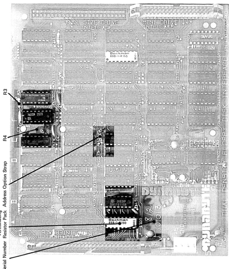
5.04 The user should refer to the Dynabyte S-IOO Card Technical Manual for
detailed infonmation for options to individual S-IOO cards and system compo-nents. Figures 5-2 through 5-4 will furnish the 5505 user with option settings necessary for a 5505 system to run diagnostic programs.
Set Up and Turn On
5.05 The following procedure will serve as a useful check list for setting
up or resetting up the 5505 Computer. For illustration purposes, the system
components are:
(1) Serial 1 Port is connected to the Serial Printer, 300 baud, and is the listing device (LST:).
5505 Technical Manual 404512
(3) Dynabyte Disk Operating System Diskette.
Set all ac line power switches to OFF.
Step Procedure
1 Install the 5505 so as not to obstruct the air flow through the
louvers in the bottom of the cabinet. Make certain there is a three-inch clearance from the rear of the fan. Dynabyte desk-type cabinets are designed to assure constant air flow through the equipment cabinets.
2 Check the option switch settings:
(1) Each S-lOO Bus card. Refer to 5.04 above.
(2) Video Terminal. Refer to the Technical Manual.
(3) Serial Printer. Refer to the Technical Manual.
3 Connect to computer system cables:
(1) EIA cable between Port 1 and the Serial Printer.
(2) EIA cable between Port 2 and the Video Terminal.
4 Connect the ac line cords:
(1) Video Terminal ac line cord to the wall receptacle.
(2) Serial Printer ac line cord to the wall receptacle.
(3) 5505 ac line cord to the wall receptacle.
5 Open the diskette drive door.
6 Turn on the ac power switches:
(1) Video Terminal
(2) Serial Printer
(3) 5505 Computer
7 Verify the following:
(1) Power on indicators on all units are lit.
(2) Fan in the 5505 is running.
(3) Disk Drive select lamp is flashing.
8 With Diskette label facing left and the slot horizontal, insert
the System Diskette into the Diskette Drive. Close the door to the drive.
9 The Video Terminal should present the Dynabyte sign-on message.
10 Refer to the 5505 Computer Operation Manual.
IMPORTANT
Tighten the retaining screws on the DB-2S-S connectors. Do
not overtighten.
Always check that the drive does not already have a
Strap Options - -...
t'Zj
..,.
\Q
C
t"1 CD
U1
I
~
n
CD ::s
rt
t"1 Q.I
~
~
tot"1
~ 0
0
~ (l)
en
tz:l en ..,.
I ~
1"0
OJ
§=
\.Q
C1> ..,.
rt
W
..
1-1
.a>
rt
..,.
0
::s
~
..,.
rt
0
::r ~
rt rt
..,.
~
en
~
5;
~trl
I
to
OJ
lO
CD
W rv
t'zJ
...,.
"l C
..,
CD
U'1
I
l\)
en
~
&'
8,
~
?5'
n
CD
en en
f
1'1
~ ...
~
rt
....
0
::s
~
....
rt
n
::r
(J)
CD
rt rt
....
~
en
NOTE: The dots on the switches indicate the direction in which the switch should be set for correct operation.
~
CD
n
::T
::s
... n
01
... ~
::s
c
OJ
~
...
'-'l c:,.,
CD U1 I W ~...
en~
~9
5;
:l~ r1'
t1
tzl 0
... I ...
." CD
,.,
OJ
--'-'l
ft)
~
W r1'
W ...
0 :l
i?
...
r1'
g.
fC
r1' r1'...
~ enSerial Number
Disk Clock Option Strap
NOTE: The dots on the switches indicate the direction in which the switch should be set for correct operation.
ROM Option Selection
Dynabyte Part No. Mnemonic 5505 Model
808088 UR10 5505-Al
808089 UR11 5505-B1 or 5505-Cl
808090 UR12 5505-Al
808091 UR13 5505-Bl or 5505-Cl
808092 UR14 5505-Al
808093 UR15 5505-Bl or 5505-Cl
5010 Model Dr ive Type
5010-01 Shugart 5010-01 Shugart
5010-01 Remex
5010-01 Remex
5010-02 Remex or Shugart 5010-02 Remex or Shugart
M
CC
v CC
0-ro
~
en
c
o
'.j:j
0.
o
III III CI,)
~
"tJ "tJ
«
C)..!!::
C (.J ' - ro
tea..
c ~
. - 0 Et; ~
.-CI,) III
~ CI,)
cc
~
CI,)
.0
E
:::l
Z
ro
.~
~
[image:35.617.74.541.123.671.2]5505 Technical Manual 404512
6. MAINTENANCE
6.01 The 5505 Computer is the result of several years of design,
develop-ment and modern electronic manufacturing. The units are designed around the latest semiconductors and integrated circuits. They operate at relatively low power levels with adequate cooling. Each 5505 Computer is operated under power
and functionally tested in the Dynabyte factory for a minimum of 72 hours
before shipnent. The 5505 Computer can be expected to operate at peak
perfor-mance for long intervals. No routine maintenance is required except occasional dusting and cleaning of the painted surfaces with a good all-purpose cleaner which does not attack or scratch painted surfaces or plastic.
Formula 409 All Purpose Cleaner Distributed by Clorox Company
Oakland, CA 94612
available from most supermarkets is well suited for this application.
Custaner Support Service
6.02 Maintenance and procedures described in this manual should be
performed in accordance with local instructions and the individual user's maintenance plan. Maintenance and repair of the 5505 Computer during the
warranty period should be limited to:
(I) returning the 5505 Computer
(2) isolation of a fault to a specific pc assembly or unit
(3) replacement of the ac line fuse once.
Repacking and Returning Material
6.03 The Dynabyte Customer Support staff is available by telephone for
assistance in troubleshooting and recommendations for repairs. If equipment is
to be returned for repair or replacement, the following procedure will
expedite repair and return of the equipment. All communications and material
should be directed to:
Dynabyte, Inc. Customer Support 521 Cottonwood Drive M[lpitas, CA 93035
(408) 263-1221 TELEX 346-359
Step Procedure
1 Call Dynabyte Customer Support by telephone and provide the
following infonnation:
2
3
4
5
6
7
(1) The nearest Dynabyte Authorized Service Center name and
numbe r, if known.
(2) The Dynabyte Model Number and Serial Number of the
equipnent. Figure 6-1 illustrates the Dynabyte Identifica-tion Plate for equipment. Nonnally this is located at the rear of the equipment.
If the fault has been traced to a specific subassembly, e.g., an S-IOO Bus card, furnish the type, part number and serial number.
'Ibis infonnation is marked on the component side of the pc
assembly.
(1) Subassembly replaced into the failed equipnent if one
was available.
(2) Subassembly to be returned to Dynabyte.
Furnish a brief statement of the problem.
Customer Support will issue a Return Material Authorization
Num-be r (RMA Number) •
(1) The RMA pennits the Dynabyte Customer Support staff to
provide better coordination of returned material.
(2) The RMA pennits the Dynabyte customer to easily
reference material returned to Dynabyte.
Package equipnent in the Dynabyte packing carton in which the equipment was received. If the original packing material is not available, Dynabyte Customer Support will provide infonnation and recommendations of material to be used.
Fill out and enclose a Dynabyte Repair Service Report with the equipment or provide the following infonnation in writing:
(1) The RMA number furnished by Dynabyte.
(2) The nearest Dynabyte Authorized Service Center.
(3) M:>del number and serial number of equipment. Refer to
Step 1 above.
(4) A brief statement of the problem.
5505 Technical Manual
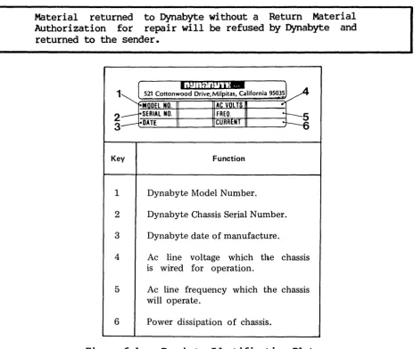
NOTE
Material returned to Dynabyte without a Return Material Authorization for repair will be refused by Dynabyte and
returned to the sender.
Diagnostics
1
2
3
Key Function
1 Dynabyte Model Number.
2 Dynabyte Chassis Serial Number.
3 Dynabyte date of manufacture.
4 Ac line voltage which the chassis
is wired for operation.
5 Ac line frequency which the chassis
will operate.
6 Power dissipation of chassis.
Figure 6-1 -- Dynabyte Identification Plate
404512
6.04 A diagnostic program supplied on a diskette is available for the 5505
Computer from a Dynabyte Authorized Service Center. This program will verify that the 5505 works in general and the diskette and hard disk drives are functioning properly. The program diskette is supplied with a Dynabyte Technical Manual describing the program operation in detail.
Fault Location
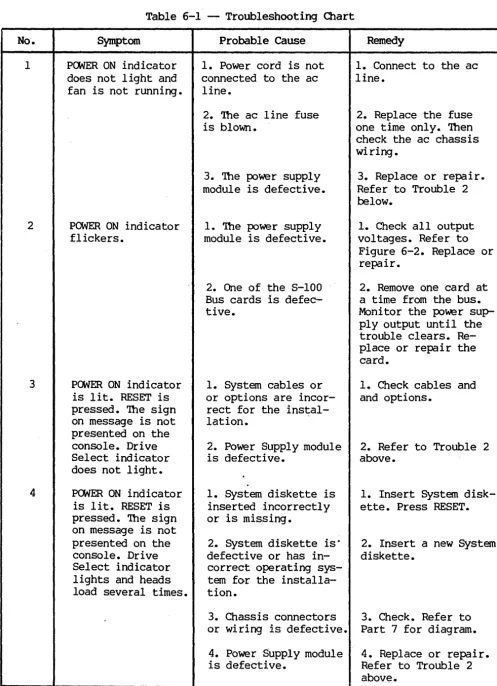
6.05 A troubleshooting chart has been included in this manual to assist the
user in isolating a fault location to one of three areas. Refer to Table 6-1.
(1) The fault symptom resulted from incorrect user operation of the 5505
Computer.
(2) The fault symptom resulted from some other piece of equipnent, e.g.,
cable, diskette storage, diskette or terminal.
[image:38.618.83.547.81.473.2](3) The fault symptom resulted from a 5505 S-IOO card or power supply module.
Table 6-1 does not tabulate all the possible symptoms, only those Dynabyte Customer Support has found most likely to occur. The diagnostic program, refer to 6.04 above, will also provide pointers for troubleshooting hardware malfunctions.
Power Supply Module Voltages and Adjustment
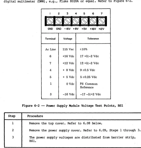
6.06 The procedure which follows will assist the user in checking and
adjusting the power supply should it be necessary. The user will need a digital multimeter (DMM),e.g., Fluke 8020A or equal. Refer to Figure 6-2.
Step
1
2
3
I 2 3 4 5 6 7
GND GND -16V +8V +5V +16V +12V
Terminal
Ac Line
6
7
4
5
1
3
Voltage
115 Vac
+16 Vdc
+12 Vdc
+ 8 Vdc
+ 5 Vdc
o
Vdc-16 Vdc
Tolerance
±10%
17 +3/-2 Vdc
12 +3/-2 Vdc
9 ±O.5 Vdc
5 ±O.25 Vdc
PS Common Reference
-17 -3/+2 Vdc
Figure 6-2 - Power Supply Module Voltage Test Points, BSI
Procedure
Remove the top cover. Refer to 6.08 below.
Remove the power supply cover. Refer to 6.09, Steps 1 through
The power supply voltages are distributed from barrier strip, BSI.
[image:39.621.56.553.229.748.2]5505 Technical Manual
4 Connect the DDM (-) lead to Terminal 1 and the (+) lead to
Terminal 4. The voltage should be:
9 + 0.5 Vdc
404512
5 If it is necessary to adjust the +8 Vdc supply to bring this
into tolerance, adjust R2 on the Modulator PC Assembly.
6 Check that each of the other voltages tabulated in Figure 6-2
are in tolerance.
Removing Assemblies
6.07 The user will need the following hand tools to remove the major
assemblies from the 5505 Computer chassis:
(1) 3/32 hex Allen wrench
(2) 11/32 socket wrench
(3) 1/4 socket wrench
(4) No. 2 Phillips head screwdriver
(5) No. 3 Phillips head screwdriver
6.08 Top Cover - The descriptions which follow view the 5505 Computer from
the front. Perform the following:
Step
1
2
Procedure
Remove the center three 3/32 hex head screws from each side of the top cover.
Remove the cover and place it in position so the woodgrain surface will not be marred during servicing.
WARNING
Hazardous Disconnect assemblies.
voltages are present inside the cabinet.
ac power before removing the cabinet cover or
6.09 Power Supply Module - is located between the card cage and the rear
panel. Perform the following:
Step Procedure
1 Disconnect the following cables:
(1) Port I/O Cable from the CPU.
(2) Disk Interface I/O Cable from the Controller.
Dress cables back over the rear panel.
2 Remove the two 6-32 Kep nuts and flat washers from the left side
of the black anodized power supply cover.
3 Remove the two 4-40 Kep nuts and flat washers from the right
side of the power supply cover.
4 Remove the power supply cover.
5 Disconnect the Motherboard Power Cable.
(1) BSI - 1 BLK (2)
- 2 BLK (2) - 3 VIO/WHT (1) - 4 ORG/WHT (2) - 5 ORG (3) - 6 RED/WHT (1) - 7 RED (2)
(2) 882 - 5 YEL (1)
6 Remove the four Phillips head 10-32 screws, star washers and
flat washer Which secure the Power Supply Module to the cabinet base.
7 Shift the Power Supply Module slightly to gain access to the
rear interior. Disconnect the ac line. This is two push-on connectors on the EMI line filter.
8 Remove the Power Supply Module from the 5505.
NOTE
Handle I/O cables with care as they can be easily damaged.
6.10 ~ Cage -- S-IOO ~ Motherboard - is located directly behind the
5505 Technical Manual 404512
Step Procedure
1 Remove all the 8-100 cards installed in the card cage.
2 Disconnect the front panel cable connector from J14, the
four-conductor pc-mounted receptacle.
3 Remove the fourteen 6-32 x 3/8 Phillips head screws and star
washers which secure the 8-100 Motherboard PC Assembly to the cabinet base.
4 Remove the card cage from the 5505 Computer.
5 Remove the eight 6-32 x 3/8 Phillips head screws and star
washers which secure the 8-100 Bus Motherboard PC Assembly to the card cage.
6.11 Front or Rear Panel - Both panels are secured to the
cabinet bezel
bY
frve-6-32 Kep nuts. It is more convenient toentire bezel. Perform the following:
respective remove the
Step Procedure
4
1 Remove the two 3/32 hex head screws from each side.
2 Remove the five 8-32 x 3/4 Phillips head screws and star washers
which secure the bezel to the cabinet base. Two of these screws also secure rubber bumpers.
3 Disconnect the electrical connections from the respective panel.
(1) Front Panel - Disconnect the ac line cable from the rear
panel and the front panel cable connector from J14, the four-conductor pc mounted receptacle.
(2) Rear Panel - Disconnect the ac line cable to the front panel and the ac line cable to the power supply. This consists of two push-on connectors on the EMI line filter.
Remove the panel.
Table 6-1 -- Troubleshooting Chart No. 1 2 3 4 Symptom
POWER ON indicator does not light and fan is not running.
POWER ON indicator flickers.
POWER ON indicator is lit. RESET is pressed. The sign on message is not presented on the console. Drive Select indicator does not light.
POWER ON indicator is lit. RESET is pressed. The sign on message is not presented on the console. Drive Select indicator lights and heads load several times.
Probable Cause
1. Power cord is not connected to the ac line.
2. The ac line fuse is blown.
3. The power supply module is defective.
1. The powe r supply module is defective.
2. One of the S-lOO Bus cards is defec-tive.
1. System cables or or options are incor-rect for the instal-lation.
2. Power Supply module is defective.
1. System diskette is inserted incorrectly or is missing.
2. System diskette is· defective or has in-correct operating sys-tem for the installa-tion.
3. Chassis connectors or wiring is defective.
4. Power Supply module is defective.
Remedy
1. Connect to the ac line.
2. Replace the fuse one time only. Then check the ac chassis wiring •
3. Replace or repair~
Refer to Trouble 2 below.
1. Check all output voltages. Refer to
Figure 6-2. Replace or repair.
2. Remove one card at a time from the bus. Moni tor the power sup-ply output until the trouble clears. Re-place or repair the card.
1. Check cables and and options.
2. Refer to Trouble 2 above.
1. Insert System disk-ette. Press RESET.
2. Insert a new System diskette.
3. Check. Refer to Part 7 for diagram.
[image:43.621.58.556.59.746.2]