warwick.ac.uk/lib-publications
Manuscript version: Author’s Accepted Manuscript
The version presented in WRAP is the author’s accepted manuscript and may differ from the
published version or Version of Record.
Persistent WRAP URL:
http://wrap.warwick.ac.uk/121460
How to cite:
Please refer to published version for the most recent bibliographic citation information.
If a published version is known of, the repository item page linked to above, will contain
details on accessing it.
Copyright and reuse:
The Warwick Research Archive Portal (WRAP) makes this work by researchers of the
University of Warwick available open access under the following conditions.
Copyright © and all moral rights to the version of the paper presented here belong to the
individual author(s) and/or other copyright owners. To the extent reasonable and
practicable the material made available in WRAP has been checked for eligibility before
being made available.
Copies of full items can be used for personal research or study, educational, or not-for-profit
purposes without prior permission or charge. Provided that the authors, title and full
bibliographic details are credited, a hyperlink and/or URL is given for the original metadata
page and the content is not changed in any way.
Publisher’s statement:
Please refer to the repository item page, publisher’s statement section, for further
information.
Automatic PLC Code Generation Based on Virtual
Engineering Model
Mohammad Jbair, Bilal Ahmad, Mus’ab H. Ahmad, Daniel Vera, Robert Harrison, Tony Ridler
E-mail: {Mohammad.Jbair, B.Ahmad, M.Ahmad.8, D.A.Vera, Robert.Harrison, T.Ridler} @warwick.ac.uk WMG, University of Warwick, CV4 7AL, Coventry, West Midlands, UK
Abstract— Today’s automotive firms, regardless the systems they use (e.g. mass production, mass customisation, just-in-time, etc.) face common challenges that can result in sudden and frequent disruptions across the supply chain. Manufacturing systems should rapidly respond to these disruptions. This can be made possible by introducing new smart engineering methods and technologies to enable realisation of high level of reconfigurable and dynamic manufacturing processes to improve the overall performance of manufacturing plants. This paper investigates a methodology to develop a digital model for a fuel-cell assembly system and then utilises the developed model to automatically generate machine’s Programmable Logic Controller (PLC) code, connectivity, and process data records. These automatically generated parts can then be used in order to create a Cyber Physical System (CPS). The aim of this paper is to demonstrate the automatic generation of the control code and structure it in order to be effectively and efficiently used in industrial applications. The on-going DIGIMAN project [1], which aims to deliver a proof of process fuel-cell assembly system for the automotive industry, is being used as a proof of concept to validate the proposed methodology and framework.
Keywords—Cyber Physical Systems; Automatic PLC Code Generation; Virtual Engineering; Digital Twin
I. INTRODUCTION
Recent initiatives, such as Industrie 4.0, promises the introduction of smart manufacturing to address the challenges faced by the manufacturing industry. Smart manufacturing is aimed to bridge the gap between digital and physical environments with the goal of optimising design, deployment and operation of manufacturing processes.
Virtual engineering and modelling tools are widely used in industry, particularly in automotive manufacturing, offer powerful capabilities and functions throughout both system and product lifecycles. However, to a large extent, the use of virtual engineering is currently confined to the design phase. There is a need to extend the use of digitalisation to deployment and operation phase. In this context, this paper is looking into development of virtual models of manufacturing systems that can be used to automatically generate structured PLC code, where this code can be deployed directly to manufacturing application. The paper investigates the current methods and practices to create a PLC code manually and automatically.
Furthermore, it investigates the existing engineering tools that consider automatic generation of a PLC code, identify the gap in these practices and propose a methodology to bridge this gap. Therefore, the novelty of this research is to automatically generate a structured PLC code that meets manufacturing applications requirements, and in-line with both maintenance and operation’s needs in order to facilitate monitoring, troubleshooting, and diagnostics activities.
II. LITERATURE REVIEW
A. PLC Software Development
PLC programming languages are widely based on IEC61131-3 standard, published in 1993 to standardise PLC programming languages. It defines five languages; Ladder Diagram (LD), Function Block Diagram (FBD), Structured Text (ST), Instruction List (IL), Sequential Function Chart (SFC) [2]. PLC vendors have widely adopted these languages. However, it is been observed, according to the survey conducted in [2], that the use of these programming languages mostly do not follow a standardised practice from code structuring perspective. Some companies (both system integrators and end-users) often define their own software structure standard to promote common look and facilitate monitoring, troubleshooting, and diagnostics activities. This also allows programmers to copy code from previous projects and edit it to match new project’s requirements. The choice of the programming languages depends on many factors such as programmer knowledge, complexity of automation task, and modification / troubleshooting frequency. Nevertheless, there is no preference to one language compared to others.
PLC software is developed either manually by a programmer or automatically using engineering tools. The sections below provide a brief overview of the existing practices for both methods within automotive industry.
B. Manual PLC programming Practices within
Automotive Industry
structuring from them. The following illustrates these practices:
Structured Transfer-Machine EDDI Programming System (STEPS) [3]:
STEPS was developed by Ford Motor Company and was extensively used across a number of Ford plants globally. STEPS was an evolution of EDDI and thus adopted a number of features from EDDI (Error Diagnostic Dynamic Indication), which was originated in 1980’s. A number of features were refined to meet the requirements of all machine types used by Ford and was published to all machine vendors of Ford Motor Company. STEPS used only LD programming language. It focused on machine maintenance and diagnostics such as displaying fault messages in a meaningful manner, and enhancing fault detection and diagnostic functions of machine control code. The program structure consists of: 1) Standard beginning; contains all ladder logic for machine modes of operations (manual and automatic) and ensure homing before start. 2) Machine Control Zone; to control an operation for the machine equipment. 3) Constantly Monitored Zone (CMZ); monitors all machine safety interlocks such as emergency stop, safety door, etc. 4) Hardware module signals; controls I/O modules. 5) Interface to Operator Terminal; controls the HMI and 6) Standard End; vendor Specific Logic.
Structured Transfer-Machine EDDI Programming System Function Block (STEP FB) [4]:
STEPS FB is designed to simplify STEP programming structure. Instead of using zones and repeating the same program in all other zones. STEP FB divides the machine into a number of components, each component is programmed using LD or ST language, and one main machine sequence that controls all of the components programmed using SFC language. STEPS FB code structure is: 1) Main Control; mode of operations, stop cycle, and go home control. 2) SFC Control; an SFC sequencer to program machine components such as Robot, Lift table, etc. 3) Component Blocks; piece of program that used to control one component of the machine. 4) Constantly Monitored Zone (CMZ). 5) HMI; controls the HMI and its messages. 6) IO Mapping; maps the I/O modules for the machine.
Ford And Siemens Transline (FAST) [5]:
FAST programming practice is a result of cooperation between Ford Motor Company and Siemens Company. It was released in 2013 for powertrain production machinery. FAST uses LD as a main programming language, though there is no emphasis on use of a specific language for vendor-specific function blocks. The structure of code for implementing control functions is very loosely defined, said that it allows flexibility to programmers to write code for most of the control functions as they want. FAST assumes that a machine consists of a maximum number of six stations and each station contains a number of components and a sequence of operation. FAST code structure includes: 1) Main Program; where all machine and its stations codes are called. 2) Machine Block; programs machine interlocks,
alarms and power diagnostics. 3) Station Blocks; control station mode of operation, station alarms, station HMI, station components, communication, traceability and station sequence of operation. 4) Safety Block; monitors all machine safety inlocks.
Function Orientated Modularisation (FOM) [6]:
FOM was introduced by ThyssenKrupp System Engineering (TKSE) GmbH in 2007. This practice considers a production system hierarchy concept. A production system is composed of Areas, each Area consists of a number of Stations. The sequence of operations for a Station is controlled via Process Steps, each Process Step controls number of Units. Units are FBs that controls actuators. FOM uses LD programming language for the high-level structure of the code. However, most of the software blocks such as Process Steps and Units are written in Instruction List. The structure of the code is modular and facilitates code reusability to a great extent.
C. Automatic PLC programming Generation Practices
Automatic code generation is a transformation of machine control behaviour, defined in a higher level of abstract during design phase, into a code that can be implemented directly into the automation system [7]. Typically, machine behaviour data are available and can be extracted from design tools that are used to define control behavior of a machine [8].
A number of researchers presented a framework and methods for automatic PLC code generation. Birgit Vogel-Heuser [9] suggested a framework to generate PLC code from Unified Modelling Language (UML) model. Real-Time Studio from Artisan was used in this research as a modelling tool. This tool defines system architecture as a prerequisite to the code generator, which in turns automatically creates IEC 61131-3 codes (SFC and ST). The generated code is structured for machine troubleshooting purposes. However, all FBs are programmed using ST language, which creates complexity and difficulty in reconfigurations and adding new functions to the machine. Martin Bergert [10] presented a framework for PLC code generation based on digital process information, modeled in DILMILA Process Engineer (DPE). The presented framework translates XML file that contains the machine specifications and generated by PDE into IEC 61131-3 code (SFC and FB). Other research conducted by Michael Steinegger [11], proposed a conceptual method to generate a PLC code from manufacturing process-engineering tools. However, this research does not demonstrate a practical solution for the proposed method.
D. Virtual Engineering of Manufacturing Systems
The purpose of virtual engineering tools is to create a digital model of manufacturing systems. Typically, virtual models consist of three main aspects: mechanical, electrical and control. Mechanical: such as geometry, layout, and kinematic. Electrical: such as power consumption, power efficiency, and power management. Control: such as machine software logic and communication links. The designed digital model allows investigation of system behaviour, as a result of components interactions by using simulation feature. The dynamic model allows validation of the system logic, as well as optimisation of the machine processes.
A wide variety of virtual engineering tools are available in the market to assist in designing and engineering of manufacturing systems. Siemens NX Mechatronics Concept Designer [12], Process Simulate, Dassault Systems DELMIA [13], WinMOD [14] and VueOne [16] are examples of these tools. These tools allow simulation of manufacturing systems in a 3D environment and enable linking the physical Inputs/Outputs with the virtual processes to ensure continuous alignment between cyber and physical worlds. As a result, a closed loop system is implemented, and optimisation can be achieved through manufacturing system’s life cycle.
E. Limitations and Gaps of Current Researches and
Practices
Most of the existing automatic code generation approaches are considered as impractical or providing incomplete solution and thus have not been put into industrial practices. Most of the carried out academic research ignore existing best practices in programming PLCs and do not meet manufacturing applications’ operational and maintenance requirements, which make activities such as machine troubleshooting are very difficult to perform. On the other hand, virtual engineering tools that are widely used in industry, mainly focus on process modelling and simulation, and do not consider the entire manufacturing lifecycle. These tools often fail to consider control system deployments, especially for PLC and HMI, which in return results more engineering time, waste of resources, and increase the overall project cost [15].
Therefore, this paper aims to propose a methodology to address these limitations in order to improve manufacturers’ competitiveness and achieve the high demand for reconfigurability.
III. METHODOLOGY
The proposed methodology in this paper aims to generate the PLC code based on the control behaviour represented by a digital model within a virtual engineering tool. The generated code is structured in a way that can be practically used in industrial application, which been represented in section IV, and considering code traceability, reconfigurability and ease of troubleshooting and maintenance activities.
A. VueOne Virtual Engineering Toolset
VueOne is a virtual engineering toolset used in this research work. VueOne is developed by the Automation Systems Group (ASG) at the University of Warwick [16]. This toolset consists of Editor, Viewer, Mapper, and Gateway. It facilitates machine lifecycle engineering and development including kinematic modelling and simulation, process planning, and mechanical and control design. VueOne facilitates component-based approach to enable component reusability and system reconfigurability. Modelling in VueOne can be broadly categoriesed into: 1) component modelling (e.g. sensor, actuator) and 2) system modelling. Components encapsulate data that defines component geometry using VRML 3D model, kinematics and control behaviour. Components can be saved in a library and be utilised throughout the machine lifecycle. System modelling can be carried out by assembling components and defining sequence of operations that define relationships and interactions between the utilised components. VueOne uses STD (State Transition Diagram) for control behavior definition that is compliant with IEC 61131-3 for process definition.
B. Research Framework
The framework targets to generate structured PLC control code by extending the capabilities of VueOne toolset. This can be seen in Fig. 1 where authors’ contributions are highlighted in green colour. The contributions are in the form of extending VueOne Mapper capabilities, so that the outcome from VCG will include: PLC Function Blocks (components FBs), Process Sequence of Operations, Machine Connectivity, and Machine Digital Twin Data Records.
The proposed framework aims to integrate and optimise the engineering phase for the PLC programming. At the design phase, machine mechanical and control behaviour (including components behavior and sequence of operations) are designed using VueOne Editor, then this design can be exported in XML format to VueOne Code Generator (VCG), which noted as the first input1 in Fig.1.
Fig. 1. Research Framework
C. PLC as a Component in Cyber Physical System (CPS)
The framework proposed in this paper aims to extend the PLC code generation and includes not only the basic PLC code to execute the automation task, but also, to generate all communication blocks and machine physical process values (digital twin data records). The communication blocks are required to connect the PLC with the plant central database via Internet of Things (IoT) protocol such as Open Platform Communication Unified Architecture (OPC UA) to create a connected digital twin and gain the benefits of data analytics and smart services such as Cause and Effect application as shown in Fig. 1. Once the PLC has the required code for physical process automation, connected with virtual world via IoT, and feedback all process values in real time, then this PLC will be acting as a component of a Cyber Physical System (CPS).
IV. PROOF-OF-CONCEPT IMPLEMENTATION
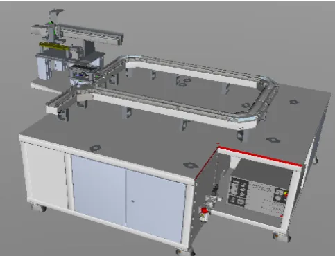
The case study in this paper demonstrates the use of VueOne toolset in order to automatically generate the PLC code for the Proof-of-Process (PoP) Demonstrator Polymer Electrolyte Membrane (PEM) fuel cell assembly system used in DIGIMAN project. The assembly system consists of four stations (i.e. cell manufacturing, fuel-cell test, fuel-cell stacking, and fuel-cell stacking test stations.) The overall assembly process is divided into zones, each zone consists of a number of workstations. PEM fuel-cells are manufactured in the first station. Each PEM cell consists of multiple layers of different material (cell layers), each layer is built using a pick and place or lamination process by dedicated stations within the PoP Demonstrator [1]. After cell manufacturing, each cell is tested. Then, a pack of the validated discrete cells is assembled into a fuel cell stack. Finally, Fuel-cell stack is tested in the fuel-cell stacking test station. For this case study, first station of the PoP Demonstrator is used. Siemens S7-300 PLC is used in the proof-of-concept implementation for this paper.
A. Methodology Workflow Implementation
The framework proposed in section III-B aims to facilitate the development of machine engineering lifecycle, by including functionality to automatically generate control
code from VueOne toolset. The implementation shall include virtual model engineering, PLC library development and VCG configuration, below sections demonstrates the implementation of this methodology:
Virtual Model:
The virtual model is a machine representation in a digital form. Fig. 2 shows virtual model of the fist station of the PoP Demonstrator, which developed in VueOne Editor.
The PLC control system requirements for this station mainly include:
1) Station sequence of operation: it describes a set of operation steps that Anode station needs to perform in order to assemble Anode layer.
Fig. 2. Anode station model in VueOne Editor from DIGIMAN project
2) Mode of operations: manual and automatic modes. During manual mode, the station steps are performed using buttons on the HMI, whereas the automatic mode executes machine sequence automatically without any human intervention. Automatic mode consists of three cycles; continuous cycle, single cycle and dry cycle, continuous cycle executes the sequence automatically for every machine cycle, single cycle executes the sequence only once, and dry cycle executes the sequence for every cycle but without material. 3) Safety machine interlocks: to ensure the operations of machine are executed in a safe manner. 4) Machine components alarms & diagnostics: to allow faster and efficient maintenance and troubleshooting. 5) Machine connectivity via OPC UA: the machine needs to communicate with the virtual world via IoT protocols such as OPC UA. 6) Machine data records: the machine should feedback the physical process data to the virtual world in order to create a connected and synchronised digital twin.
[image:5.595.316.558.242.427.2]Fig. 3. Process component STD in VueOne Editor
PLC Library:
VCG maps each component from the modeled machine with a FB from the PLC library. Fig. 4 shows the interface of a template FB with all inputs/outputs interfaces. Although machine components functionalities are different, the structure of FBs is same for all components. All FBs are programmed using LD language and published with version control in the library.
The FB considers two mode of operations; automatic and manual modes, if automatic mode is selected, then based on the sequence of operation, the automatic command for the component will be performed using “Auto Cmd” input. “Handshake” input will be activated when the machine sequence of operation executes all steps. If manual mode is selected, then buttons from the HMI will operate the component using “Man Cmd” input. During movement from home to work positions, safety interlocks are checked using “Home Interlocks” and “Work Interlocks” inputs. “PDIs” inputs represent the physical inputs from the machine and “PDOs” are the command to generate physical outputs. When the automatic or manual command is activated, a fault timer will trigger to check the physical feedback. If this feedback is not activated within the “Fault Timer” time, then a “Fault” will be generated. Fault can be reset using “Fault Reset” input.
“Alarm” output is acting as the diagnostics feature for the machine during operation and maintenance. The output is a value range between 1 to 10, this output helps the user to monitor and diagnose the machine during operations. Each number indicates an alarm state of the component, for example, number 1 indicates unit component is faulty, number 7 indicates unit inhibit, etc. “Data Record” output is an array of component’s process values that communicated back to the central database in order to create the connected digital twin. This output will be triggered once the component end of operation or movement is completed.
[image:6.595.317.556.55.208.2]DIGIMAN project has utilised this FB template in order to generate machine components FBs, such as multi-position
Fig. 4. Function Block example from PLC Library
electrical cylinder, pneumatic cylinder, Robot arm for pick and place and other components.
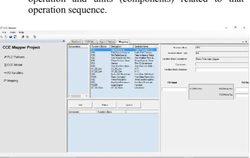
VueOne Code Generator (VCG):
In order to generate the target control code, VCG interface is used as shown in Fig. 5. It lists all components, which have been imported from the XML file and lists all FBs for the components. By selecting the component (left side) and then select FB (right side), the VCG links the component with the FB and create the PLC FBs. Finally, the user can generate the PLC code using code generation function provided in the VCG interface. The Process Sequences is generated automatically based on the STD diagram that programmed in the virtual model as one-to-one generation to a FB, this FB uses S7 Graph programming language.
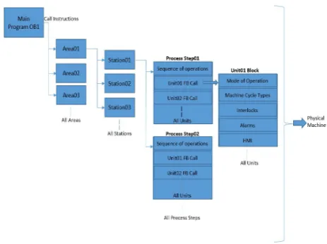
The automatically generated PLC code from VCG is structured to meet the operational and maintenance requirements and bridge the gap that described in section I-E. A brief description of the code structure is given below, and Fig. 6 has demonstrated the structure as a hierarchy diagram.
1 Main program OB1 calls production line areas’ FBs. 2 Every area consists of a number of stations.
3 Each station calls number of Process Steps.
4 Each Process Step calls the main sequence of operation and units (components) related to that operation sequence.
[image:6.595.316.565.534.691.2]Fig. 6. PLC code structure generated from VCG
B. VCG code generation for DIGIMAN case study
[image:7.595.37.282.343.457.2]The case study considers the first station of the PoP Demonstrator (Anode station), which places the Anode layer of the PEM fuel cell. The digital model for this station has been illustrated in Fig. 2 and process sequence has been explained in Fig. 3. The generated code from VCG tool is shown in below Fig. 7.
Fig. 7. Anode station PLC generated code from VCG tool.
V. CONCLUSION AND FUTURE WORK
The paper demonstrates structured PLC automatic code generation based on virtual engineering model and process planning data available in VueOne toolset. The generated code has been structured in order to be in-line with currently manual programming practices used in industrial applications. The generated code can be monitored and changed by technicians if required (such as bypassing an interlock due to a faulty sensor). Furthermore, it considers simple programming style for easy code tracing, machine monitoring and diagnostics, maintenance activities, and machine future reconfiguration and upgrades activities. This research paper also considers another angle of the PLC code generation, which is connectivity and machine data records. This is an important aspect of smart manufacturing systems, where the PLC needs to be a part of the CPS and provide all required IoT connectivity as well as real time process data to feed it back to the virtual world and create a connected digital twin.
The case study implementation was carried out on a full-scale industrial machine. The proposed framework was validated on the Anode station. Moreover, the created data records are stored in a central database (digital twin) for further data analytics by the Cause and Effect application, which been developed by DIGIMAN stakeholders.
Future work will show how this methodology can be extended to generate the PLC code for the entire DIGIMAN stations, and validate and evaluate the generated code for further components within this project such as VFD, RFID tag, smart sensors and actuators.
VI. ACKNOWLEDGMENT
The research leading to these results has received funding from the Fuel Cells and Hydrogen 2 Joint Undertaking under grant agreement No 736290, DIGIMAN. This Joint Undertaking receives support from the European Union’s Horizon 2020 research and innovation programme, Hydrogen Europe and Hydrogen Europe research. The authors gratefully acknowledge the contribution of Dr. Tony Wilson (Intelligent Energy), David Urquhart (WMG) and Jiayi Zhang (WMG).
VII.REFERENCES
[1] H. 2020, “DigiMan Project.” [Online]. Available:
http://digiman.eu/index.php. [Accessed: 12-Nov-2018].
[2] V. Hajarnavis, K. Young, V. Hajarnavis, and K. Young, “An
investigation into programmable logic controller software design techniques in the automotive industry,” 2015.
[3] F. M. Company, “STEPS Specification,” 1996.
[4] F. M. Company, “DVM4 Auto Station Engine Assembly
Specification.”
[5] Siemens, “PTO Manufacturing Engineering FAST PLC Structure
Manual,” 2012.
[6] ThyssenKrupp, “STEP 7 Programming Course FOM Training
Course,” 2002.
[7] S. Lee, M. A. Ang, and J. Lee, “Automatic generation of logic
control,” p. 2006, 2006.
[8] M. Jbair et al., “Industrial Cyber Physical Systems : A Survey for
Control-Engineering Tools.”
[9] B. Vogel-heuser, M. Ieee, D. Witsch, and U. Katzke, “Automatic
Code Generation from a UML model to JEC 61131-3 and system configuration tools,” pp. 1034–1039, 2005.
[10] M. Bergert, C. Diedrich, M. Germany, J. Kiefer, and T. Bär,
“Automated PLC Software Generation Based on Standardized Digital Process Information Institute of Automation Technology ( IFAT ) Function and Production Modeling ( GR / EPF ),” pp. 352–359, 2007.
[11] M. Steinegger and A. Zoitl, “Automated Code Generation for
Programmable Logic Controllers based on Knowledge Acquisition from Engineering Artifacts : Concept and Case Study,” no. Xml, pp. 1–8, 2012.
[12] Siemens, “NX MCD.” [Online]. Available:
https://www.plm.automation.siemens.com/global/en/products/me
chanical-design/mechatronic-concept-design.html. [Accessed:
12-Nov-2018].
[13] D. Systems, “Delmia.” [Online]. Available:
https://www.3ds.com/products-services/delmia/. [Accessed: 25-Jan-2018].
[14] “WinMOD.” [Online]. Available: http://www.winmod.de/en/.
[Accessed: 25-Jan-2018].
[15] M. Pellicciari, A. O. Andrisano, F. Leali, and A. Vergnano,
“Engineering method for adaptive manufacturing systems design,” pp. 81–91, 2009.
[16] R. Harrison, D. Vera, and B. Ahmad, “Engineering Methods and