Thesis by Justin Boland
In Partial Fulfillment of the Requirements for the Degree of
Doctor of Philosophy
CALIFORNIA INSTITUTE OF TECHNOLOGY
Pasadena, California 2005
© 2005
ACKNOWLEDGEMENTS
Yu-Chong Tai, Trevor Roper, Tanya Owen, Wen Hsieh, Ellis Meng, Tom Tsao, Mattieu Liger, Qing He, Chi-Yuan (Victor) Shih, Scott Miserendino, Po-Jui (PJ) Chen, Nick Lo, Jayson Messenger, Svanhild (Swan) Simonson, Yuan-Heng (Denny) Chao, JR Heberle, the rest of the Caltech Micromachining Group, my candidacy committee (Yu-Chong Tai, Ken Pickar, David Rutledge, Axel Scherer, Kaushik Bhattacharya), my thesis committee (Yu-Chong Tai, Ken Pickar, David Rutledge, Melany Hunt, Changhuei Yang), funding sources (DARPA, AMRDEC, NSF), and my wife Stacey Boland.
Dedication:
A
B S T R A C T
Micro Electret Power Generators
T
A B L E O F
C
O N T E N T S
I. Introduction ... 1
I.1. Scope of thesis ... 1
I.1.a. Organization... 2
I.1.b. Problem Statement... 4
I.2. Electricity... 5
I.2.a. Generating Electricity ... 5
I.2.a.i. Triboelectricity... 7
I.2.a.ii. Photovoltaic Generation ... 7
I.2.a.iii. Chemical Generation ... 8
I.2.a.iv. Electromagnetic Generation... 8
I.2.a.v. Electrostatic Generation... 9
I.2.b. Alternative Energy... 10
I.2.b.i. Portable Alternative Energy ... 11
I.3. Energy Harvesting ... 13
I.3.a. Energy Harvesting Methods ... 15
I.3.b. Survey of Kinetic Energy Harvesting Devices... 17
I.3.b.i. Alternative Definition: Power Scavenging... 17
I.3.b.ii. Figures of Merit... 18
I.3.b.ii.1. Linear Energy Harvesters... 18
I.3.b.ii.2. Rotational Energy Harvesters... 22
I.3.b.iv. Linear Electromagnetic Power Generators... 26
I.3.b.v. Piezoelectric Power Generators ... 28
I.3.b.vi. Charge Shuttle ... 30
I.3.b.vii. Electrostatic Power Generators ... 31
I.4. Displacement Current Power Generators... 33
I.4.a. Origin of Displacement Current ... 33
I.4.a.i. Displacement Current in a Capacitor... 33
I.4.b. Displacement Current For Power Generation ... 35
I.4.b.i. Variable Distance Electret Power Generators... 37
I.4.b.ii. Variable Area Electret Power Generators ... 38
I.4.b.iii. Variable Permittivity Electret Power Generators ... 39
I.5. Physical Scaling ... 40
I.5.a. Physics-Based Definition of MEMS... 40
I.5.b. Process-Based Definition of MEMS ... 42
I.5.c. Applying MEMS... 43
I.6. Funding ... 44
II. Electrets... 54
II.1. Electret Classification... 56
II.1.a. Heterocharge Electrets... 56
II.1.b. Homocharge Electrets ... 57
II.2. Charging Methods ... 58
II.2.a. Triboelectric... 58
II.3. Measurement Techniques ... 63
II.3.a. Charge Density ... 63
II.3.a.i. Error in Depth of Charge... 65
II.3.a.ii. Lateral Resolution of Charge ... 65
II.3.b. Depth Sounding Techniques... 67
II.4. Uniformity ... 69
II.4.a. Floating Metal Layer Electret... 69
II.4.a.i. Floating Metal Layer Process... 70
II.5. Conclusions ... 72
III. Variable Area Rotational Electret Power Generator... 73
III.1. Introduction ... 73
III.1.a. Related Works ... 74
III.1.b. Micromachining Electrets... 75
III.2. Theoretical Development ... 76
III.3. Design and Fabrication... 82
III.3.a. Design Optimization ... 82
III.3.a.i. Charge Density... 83
III.3.a.ii. Dielectric Constant... 83
III.3.a.iii. Gap Spacing... 84
III.3.a.iv. Number of Poles... 85
III.3.b. Fabrication Considerations ... 86
III.3.b.i. Teflon Processing... 88
III.3.d. REPG Version 2.0 ... 93
III.3.e. REPG Version 3.0 ... 96
III.3.f. REPG Version 4.0, 5.0 / Prototype Version 1.0, 2.0 ... 97
III.4. Experimental Results... 99
III.4.a. Charge ... 99
III.4.b. Testbeds... 100
III.4.b.i. Rotational Speed ... 101
III.4.b.ii. Rotational Angular Misalignment... 102
III.4.b.ii.1. Testbed Version 1... 103
III.4.b.ii.2. Testbed Version 2... 104
III.4.b.ii.3. Testbed Version 3... 107
III.4.c. Power Generation Tests... 109
III.4.c.i. REPG V1.0 on Testbed Version 1 ... 109
III.4.c.ii. 32 Pole REPG V2.0 ...111
III.4.c.iii. 64 Pole REPG V2.0 ... 112
III.5. Conclusions ... 114
IV. Liquid Rotor Electret Power Generator... 116
IV.1. Introduction... 119
IV.2. Theory ... 121
IV.2.a. Using Liquid Metal Instead of Liquid Dielectric ... 125
IV.3. Design and Fabrication ... 127
IV.3.a. General Considerations ... 127
IV.3.a.ii. Cavity Material... 128
IV.3.a.iii. Electret ... 129
IV.3.b. Fabrication... 132
IV.3.b.i. LEPG V1.0: Quick and Dirty... 132
IV.3.b.ii. LEPG V2.0: PDMS Mold and Process Refinements... 134
IV.3.c. LEPG V3.0: Multiple Channels on Single Chip ... 136
IV.4. Experimental Details... 138
IV.4.a. Data ... 139
IV.4.a.i. Replacing Mercury with Steel Beads ... 139
IV.4.a.ii. Parallel Arrays... 142
IV.4.a.iii. Serial Arrays... 143
IV.4.a.iv. Non-Obvious Electrical Connections ... 145
IV.5. Conclusions... 148
V. Conclusions and Future Work... 150
V.1. Rotary Electret Power Generator ... 150
V.2. Liquid Rotor Electret Power Generator... 158
T
A B L E O F
F
I G U R E S
Figure I-1 Measured vibrations from a microwave oven ...10
Figure I-2 Electrical power delivered over time from various sources [5]...13
Figure I-3 Generator architecture comparison...20
Figure I-4 Diagram of Seiko’s Kinetic line of energy harvesting watches...23
Figure I-5 Exploded Diagram of Seiko’s Kinetic line of energy harvesting watches...24
Figure I-6 Lab test of Seiko’s Kinetic generator. Speed corresponds to the relative rotation of the magnet to the coil. ...25
Figure I-7 Linear electromagnetic power generator developed by Perpetuum [15]. ...26
Figure I-8 Perpetuum’s 2-terminal power generator package [16]...27
Figure I-9 PMG0100 Evaluation Model [17] ...27
Figure I-10 Piezoelectric cantilever with proof mass for converting vibrations to electricity...28
Figure I-11 Schematic for piezoelectric windmill power generator ...29
Figure I-12 Cross section of a charge shuttle ...30
Figure I-13 Drive circuitry for the charge shuttle...31
Figure I-14 In-plane variable gap capacitance micromachined power generator...32
Figure I-15 Out-of-plane variable gap capacitance micromachined power generator...32
Figure I-16 Pulsed Chemical-Electret Generator system concept ...45
Figure I-17 Pulsed combustion of a prototype symmetric PCTR in natural aspirating mode at three different phase angles ...48
Figure I-18 Semi-ceramic combustion chambers ...50
Figure I-19 Two interconnected fluidic microcavities...50
Figure I-20 Coupon...50
Figure I-21 CFD simulation of a turbine ...51
Figure I-22 Proposed new design for pulsed combustor thermal resonator and shaker generator system. ...53
Figure II-2 Contour plot of electric potential from a sheet electret ...54
Figure II-3 Streamline plot of electric field from a sheet electret...55
Figure II-4 Heterocharge by polarization ...56
Figure II-5 Homocharge electret with implanted electrons ...56
Figure II-6.Triboelectrically charged Teflon chip...59
Figure II-7 Charge density of implanted Teflon using the back lighted thyratron ...61
Figure II-8 Mean charge depth for corona charged FEP Teflon ...62
Figure II-9 Isoprobe mounted on X-Y micropositioner...64
Figure II-10 Charge density measurement used to determine minimum distance between data points. ...66
Figure II-11 Average charge density and standard deviation when dropping data points from dataset used to produce Figure II-10. ...67
By statistically comparing neighboring data points from the scan of Figure II-10, it was determined that a measurement spacing of 1mm would allow both average measurement of charge and high contrast as shown in Figure II-12...67
Figure II-13 Polarization map of a 11 µm thick PVDF film poled with a T-shaped electrode. At z=1μm (top graph), the polarization is significantly lower than in the bulk. The arrow indicates the direction of the high-resolution scan [ibid]...68
Figure II-14 Charge implanted in a chip with floating metal layer. ...70
Figure III-1 First electret power generator. Tada (1992) ...74
Figure III-2. Schematic of electret generator (cross-section view). ...76
Figure III-3. Perspective view of electret generator showing a 4-pole rotor and stator. ...77
Figure III-4 Equivalent circuit for variable area electret power generator. ...78
Figure III-5 Used to find the critical width w from gap distance ...85
Figure III-6 Table of different Fluorinert solvents, which are used to dilute Teflon AF 1601-S ...89
Figure III-7 Process flow for first version of REPG...91
Figure III-8 REPG V1.0 mounted on testbed version 1. Photo taken before rotor and stator are aligned...92
Figure III-10 Process flow for bulk-etched electrets ...94
Figure III-11 Bulk-etched Teflon with anchors before reflow step. ...95
Figure III-12 Bulk-etched Teflon with anchors after reflow step. ...95
Figure III-13 REPG version 4.0. Cutaway view of final assembled device including bearings. ...97
Figure III-14 Stator for REPG version 5.0. This design incorporated the use of bulk-etched cavities...98
Figure III-15 Charge density measurements of a 4-pole floating metal layer electret that is triboelectrically charged ...99
Figure III-16 Proceedure for measuring angular misalignment...102
Figure III-17 Law of reflections on laser trajectory used to find angular misalignment ...102
Figure III-18 Testbed with rotor and stator mounted...103
Figure III-19 Side view of ball joint ...104
Figure III-20 Inside View of ball joint...104
Figure III-21 Side view of testbed with rotor and stator mounted...106
Figure III-22 Newest testbed for REPG ...108
Figure III-23 Power output from 3 experimental trials using different load resistances and theoretical power of a continuously load matched system...110
Figure III-24 Power measured and theoretical vs. rotation for the 32-pole power generator with a 600kΩ load, -5x10⁻⁴C/m2 charge implanted, 2cm diameter rotor-stator pair, and 4.25μm thick Teflon electret...111
Figure III-25 Load matching test of a 64 pole generator on testbed version 3 at 2.5kRPM ...112
Figure III-26 Power vs. rotation for the 64-pole power generator with a 50.3kΩ load...113
Figure III-27 Comparison of power measured from an actual Seiko watch to rotational electret power generators. ...114
Figure IV-1 Femlab modeling of spatial potential from an electret that is modified by a sphere of mercury...117
Figure IV-2. LEPG conceptual image...119
Figure IV-3. Equivalent circuit for each half of the channel. ...121
Figure IV-5 Mathematically defined capacitances over one cycle. No allowance has been made for stray capacitance. ...124 Figure IV-6 LEPG with a small droplet of water in the channel. ...132 Figure IV-7 Process Flow a. deposit metal on glass substrate b. pattern metal c.
spin-on Teflon AF d. mask design used. ...134 Figure IV-8 Mold Master for Sylgard 184 and peeled PDMS...135 Figure IV-9 Assembled LPG Device. Clear epoxy binds the top plate to the
bottom plate and prevents the mercury from leaking...135 Figure IV-10 Electrode pattern for 6x3 cavities with 2 top and 2 bottom
electrodes per cavity. ...136 Figure IV-11 Assembled LEPG device with cutaway to reveal bottom
electrodes...137 Figure IV-12 Test setup for LEPG mounted on shaker...138 Figure IV-13 Power generated in LPG V2.1 with 100μm Teflon PTFE...140 Figure IV-14 Still-frame position 1 taken at 2000fps while shaking at 60Hz and
1 mm peak to peak. ...141 Figure IV-15 Still-frames position 2 taken at 2000fps while shaking at 60Hz and
1 mm peak to peak. ...141 Figure IV-16 Experimental values for parallel channels shaking of 2.58 mm
peak-to-peak at 60Hz. ...142 Figure IV-17 Experimental values for serial columns shaking at 1 mm
peak-to-peak at 60Hz...143 Figure IV-18 Experimental values for shaking at 2.58 mm peak-to-peak at 60
Hz and Rl of 4 MOhm...144 Figure IV-19 Diagram showing all connections across LEPG ...145 Figure IV-20 Voltage waveforms with resistors connected across V3-V4,
V1-V2, and V2-V3 on an LEPG device shaking at f = 60 Hz,
displacement = 2 mm p-p, R = 14 MOhm for all three resistors. ...146 Figure IV-21 Waveforms from same connections as above in Figure IV-19
except only one resistor is connected at any time. ...147 Figure V-1 Comparison of Seiko’s Kinetic electromagnetic power generator to
the REPG...151 Figure V-2 Liquid bearing concept for gap control in REPG. ...152 Figure V-3 Micromachined magnets (red is north pole up, blue is south pole up)
Figure V-4 Theoretical plot of rotational speed versus gap displacement showing that higher rotational speeds are necessary when gap
distance is large. ...154 Figure V-5 A Wimshurst machine used to generate electricity from electrostatics
and triboelectricity...156 Figure V-6 Decay curve of charge 1farad supercapacitor due to leakage current
T
A B L E O F
T
A B L E S
Insert I-1. Brief history of electricity [1-4] ...6
Table I-2. Comparisons of power conversion techniques...9
Table I-3. Power density of various electrical power generators. * Flux density measured in (μW/cm2)...15
Table I-4. Survey of power sources [9, 10]...16
Table I-5 Power conversion definitions ...20
Table II-1 Process flow for floating metal layer electret ...71
Table III-1 REPG parameters for optimization...83
C
H A P T E R
1
I.
I
NTRODUCTION
I came to the California Institute of Technolgy for the purpose of applying my background in physics to real world problems, or as I put it in my statement of purpose on my application, “I want to build cool stuff.” I think this thesis is true to that purpose.
I.1.
S
COPE OF THESISThe central focus of this work is the generation of electricity using mechanical forces in combination with permanent electrostatic fields. Electric fields provide a powerful force for doing work, which is inversely proportional to the square of the distance between charged particles. To take advantage of this large force, electrostatic devices must be made with high precision and small dimensions. A wealth of technological knowledge for producing high-precision, micro-scale, electrical and mechanical system exists in the field of micromachining. The work in this thesis was performed in the Caltech Micromachining Laboratory, which provides micromachining equipment and process technology expertise necessary to build small electrostatic devices to generate electricity.
alternating displacement current through an external circuit, which provides useful electrical power.
Two mechanisms are explored and proven feasible to produce electricity from an electrostatic field in two new power generating devices. First, a device is build that uses a rotational torque to modify the overlapping area of a charged capacitor structure. Second, a vibrational mechanical force is used to shake a fixed capacitor structure that contains an air gap and liquid that can flow into and out of the air gap, which changes the strength of an electric field within the charged capacitor structure. This thesis demonstrates 2.5mW of power generated from a 2cm diameter rotary generator at 12kRPM and 10μw for a 0.1cm3 linear shaking generator at 60Hz.
I.1.a.
O
RGANIZATIONThis thesis is divided into five chapters: Introduction, Electrets, Variable Area Rotational Electret Power Generator, Liquid Rotor Electret Power Generator, and Conclusions and Future Work.
to the development project followed by the delineation of duties. Although this project is funded as part of a power generation system, the generators described are separate and complete systems worthy of an entire thesis.
Chapter 2 explains “electrets”, which provide the electric field used to generate electricity in the generators presented. This chapter provides examples of electret fabrication, as well as the specific micromachining technology used in this work and the unique electron implantation system used in the Caltech Micromachining Laboratory. Measurement techniques used to characterize the electret are then explained. Finally, electrets produced for this work are analyzed, and a new fabrication method for producing superior uniformity is explained and characterized.
Chapter 3 covers the world’s first micromachined rotary electret power generator (REPG). Background information is given that sets the stage for applying micromachining techniques to produce the REPG. New theory is development to address the design of this new device. Design and fabrication of several versions of the device are presented as well as the experimental results.
fabricate LEPG devices. LEPG devices are tested over a wide range of variables, as well as parallel and serial combinations of devices and some non-obvious electrical connections that prove advantageous.
Chapter 5 summarizes the contributions of this work and proposes some future work using the insight gained during this course of study. As with any new area of exploration, a great deal of knowledge is learned but much more awaits the eager researchers who follow.
I.1.b.
P
ROBLEMS
TATEMENTI.2.
E
LECTRICITYOf the four fundamental forces of nature: strong force, electromagnetic force, weak force and gravitational force, the electromagnetic force is the best understood. The origin of the electric force is the negatively charged elementary particle, the electron, which exerts an attractive force towards positively charged protons and a repulsive force towards other negatively charged electrons. Since all stable matter is made of these elementary particles, the electric force dominates most observed interactions between materials.
The magnetic force is a consequence of electrical charge in motion, and consequently the electromagnetic force is simply a unified theory for explaining the physical interactions of electricity and magnetism.
Electric and electricity are the general term associated with stationary and moving electric charges. In the past two centuries, humans have become especially adept at moving electrical charges.
I.2.a.
G
ENERATINGE
LECTRICITYFrom the writings of Thales of Miletus it appears that Westerners knew as long ago as 600 B.C. that amber becomes charged by rubbing. There was little real progress until the English scientist William Gilbert in 1600 described the electrification of many substances and coined the term electricity from the Greek word for amber. As a result, Gilbert is called the father of modern electricity. In 1660 Otto von Guericke invented a crude machine for producing static electricity. It was a ball of sulfur, rotated by a crank with one hand and rubbed with the other. Successors, such as Francis Hauksbee, made improvements that provided experimenters with a ready source of static electricity. Today's highly developed descendant of these early machines is the Van de Graaf generator, which is sometimes used as a particle accelerator. Robert Boyle realized that attraction and repulsion were mutual and that electric force was transmitted through a vacuum (c.1675). Stephen Gray distinguished between conductors and nonconductors (1729). C. F. Du Fay recognized two kinds of electricity, which Benjamin Franklin and Ebenezer Kinnersley of Philadelphia later named positive and negative.
Insert I-1. Brief history of electricity [1-4]
Remarkable advances in human understanding of electricity began occurring in the 18th
I.2.a.i. TRIBOELECTRICITY
The generation of electricity from rubbing two dissimilar things together is known as “triboelectricity,” which is the first source of man-made electricity. Everyone has seen examples of triboelectricity in the form of lightning, which is caused by charge transfer between air and water. Children generate triboelectricity by dragging their shoes on carpet to build up a charge that allows them to shock a friend. This method of generating electricity is simply the conversion of mechanical energy to electrical energy through friction. This motion causes electrons to be transferred from one material to another, causing an excess of electrons on one material and a deficiency of electrons on the other.
While this is the oldest form of electricity, it is still the least understood. Modern theses on triboelectricity still fail to lead to reliable laws that can quantify or predict the outcome of a triboelectric event. The unpredictability of triboelectricity prevents it from being widely used as a source for electrical energy.
I.2.a.ii. PHOTOVOLTAIC GENERATION
energy from the sunshine or indoor lighting as a power source is a convenient way to generate electrical power.
I.2.a.iii. CHEMICAL GENERATION
The battery is probably the most recognized device for producing electrical energy. The battery is a chemical system that generates electricity as the byproduct of a chemical reaction. Chemical generation of electricity is limited to the quantity of chemicals in a system, but is well known as an effective method to store a large amount of useful energy in a small, portable space that can easily be converted to electrical energy.
I.2.a.iv. ELECTROMAGNETIC GENERATION
generators do not scale well to very small dimensions due to the need for many coils of wire and the difficulty in maintaining strong magnetic dipoles in small magnets.
I.2.a.v. ELECTROSTATIC GENERATION
Electrical power generation is the production of a useful electrical current at some voltage. Typically, AC current is produced via a varying magnetic field and collecting electrical current from loops of wire. Electrical current can also be generated by a chemical reaction, photoelectric effect, triboelectric effect, quantum-thermal effect, or in the case of this work by the influence of a purely electric field.
Table I-2. Comparisons of power conversion techniques.
common being lights and motors. Machines waste kinetic energy in the form of vibration. AC electricity commonly has a frequency of 60 Hz. When a motor is operated at 60 Hz it will inevitably produce vibrations at this drive frequency and multiples of the drive frequency. Figure I-1 describes the measured vibrations of a simple microwave oven with a fundamental mode around 120Hz and roughly a 1ω2 displacement[5]. The obvious question, then, is “can wasted vibrations be reclaimed for some other use?”
Figure I-1 Measured vibrations from a microwave oven
I.2.b.
A
LTERNATIVEE
NERGYA form of alternative energy that is not renewable is nuclear fission since the source of this energy, radioactive elements, are changed in a physical manner that is not feasibly reversible within a human lifespan.
I.2.b.i. PORTABLE ALTERNATIVE ENERGY
Since chemical cell batteries are the standard for portable electricity, there is an analog to alternative energy that is called “portable alternative energy.” The major disadvantage of alkaline and other non-rechargeable batteries is that they cannot be made to contain more energy without industrial reprocessing. Rechargeable batteries require connection to an energy source to regain their power, and they have a limited number of cycles before the chemistry degrades to the point where industrial reprocessing is also necessary. Batteries are useful because of their large energy density, but they require maintenance.
Demand for power supplies used in portable products in the United State is projected to increase 6.1 percent annually to $10.3 billion in 2008. Batteries are the standard technology for providing portable power, but they have limited lifetimes. The amount of batteries being disposed of in landfills became so great that in 1996 President Clinton signed into law the Mercury-Containing and Rechargeable Battery Management Act in an effort to reduce the toxicity of landfills and incinerator ash that is caused by the heavy metals found in batteries [6]. This act significantly contributes to the recycling of batteries, but it has not curbed the dependence on chemical cells for portable energy. Re-usable batteries all suffer from limitations that prevent them from being cheaper and/or more effective.
In contrast, solar cells used in calculators and watches provide energy by converting an external energy source, the sun or indoor lighting, to electrical power. Furthermore, solar cells do not degrade noticeably over the lifetime of the device. This alternative approach to providing portable electrical power can eliminate the dependence on batteries and maintenance, which has allowed for new applications, like earth-orbiting satellites, that would not otherwise be possible with chemical cell batteries.
I.3.
E
NERGYH
ARVESTING“Energy Harvesting” is the term used to describe converting wasted ambient energy into useable electrical energy. For example, bridges vibrate as vehicles travel over them, and those vibrations have kinetic energy that could be used for generating electricity. An energy harvester might convert enough of the vibration into electricity to operate a sensor and wireless node to monitor the temperature, stress, or humidity on the bridge and relay the information to listening posts for analysis.
Energy harvesters promote innovation by eliminating conventional power supplies. Devices that convert the vibrations to usable electricity would allow new applications, such as “set and forget” remote sensors that rarely or never need maintenance. Networks of sensors can be dispersed to monitor an area, such as “Smart Dust” [7, 8].
Natural sources of energy are ubiquitous. Solar energy, gravitational energy in the form of ocean waves and hydroelectric dams, and wind energy are already being harvested to produce electricity.
Harvesting applications must receive some input energy from the environment. Assuming the environmental energy is relatively constant, Figure I-2 clearly shows the advantages of energy harvesting over time. Both solar energy (indoors and outside) and vibrational energy in the environment may fluctuate within the gray ranges shown in Figure I-2, but they never cease as a source of environmental energy.
I.3.a.
E
NERGYH
ARVESTINGM
ETHODSPower Density (μW/cm3) Over one year Over 10 years Over 100 years
Solar* (Direct Sun) 10000 10000 10000
Solar* (indoor) 6 6 6
Thermoelectric(DT=10°C) 15 15 15
Vibration (Piezoelectric) 100 100 100
Vibration (Electrostatic) 50 50 50
Vibration (Electret) 1000 1000 1000
Biomotion Energy (inside shoe) 330 330 330
Batteries (Lithium) 45 4.5 0.45
Hydrocarbon (micro heat engine) 330 33 3.3
Fuel Cells (Methanol, theoretical) 280 28 2.8
Table I-3. Power density of various electrical power generators. * Flux density measured in (μW/cm2)
Power source (μW)/cm3 (Joules)/cm3(μW)/cm3/yrStorage needed?Regulation?Available?
Primary battery N/A 2,880 90 No No Yes
Secondary battery N/A 1,080 34 N/A No Yes
Micro fuel cell N/A 3,500 110 Maybe Maybe No
Ultracapacitor N/A 50–100 1.6–3.2 No Yes Yes
Heat engine 1 x 10⁶ 3,346 106 Yes Yes No
Radioactive (63Ni) 0.52 1,640 0.52 Yes Yes No
Solar (outside) 15,000* N/A N/A Usually Maybe Yes
Solar (inside) 10* N/A N/A Usually Maybe Yes
Temperature 40*† N/A N/A Usually Maybe Soon
Human power 330 N/A N/A Yes Yes No
Air flow 380‡ N/A N/A Yes Yes No
Pressure variation 17§ N/A N/A Yes Yes No
Vibrations 375 N/A N/A Yes Yes No
LEPG 100 N/A N/A Yes Yes No
* Measured in power per square centimeter, rather than power per cubic centimeter. † Demonstrated from a 5ºC temperature differential.
‡ Assumes an air velocity of 5 m/s and 5% conversion efficiency. § Based on 1 cm3 closed volume of helium undergoing a 10ºC change once a day.
Table I-4. Survey of power sources [9, 10]
I.3.b.
S
URVEY OFK
INETICE
NERGYH
ARVESTINGD
EVICESPreceding this work are many examples of energy harvesting devices. Many of these devices are built using micromachining tools, while other devices are just small. The physical principles that govern each device are very different, and now the scope will be narrowed to better explore the area of interest. Specifically, the focus of this thesis is on converting raw kinetic energy into electrical energy.
I.3.b.i. ALTERNATIVE DEFINITION:POWER SCAVENGING
Power scavenging is the art of harvesting small amounts of energy from the local environment without significantly affecting the original environment. Power scavengers are a subset of energy harvesters where the available ambient energy converted is small compared to the total energy available so that the presence of the device is not noticed. The distinction of a device being a “power scavenger” becomes relevant depending on the end application.
I.3.b.ii. FIGURES OF MERIT
Energy conversion devices convert one form of energy to another, and the typical measure of the success of the device is the efficiency: the ratio of the output power to the input power. The second law of thermodynamics can be used to prove that the output power can never be greater than the input power, thus efficiency is always 100% or less. For any device that delivers electricity, the first metric used to characterize it is efficiency.
However, for power scavenging devices the input energy is much less than the available energy. The measure of efficiency ignores the requirements placed on the design of power scavengers, namely that the volume and mass of the generator must be minimized for the scavenger to be an attractive power solution. That is why the most important measure that is used in comparing power scavenger devices is the power output divided by the volume of the generator, or the power density.
I.3.b.ii.1. Linear Energy Harvesters
have operational maximums at the same frequency, volume, mass, or acceleration, which makes comparing them difficult.
For vibration driven power generators, power output has been shown to scale in proportion to the source motion amplitude (Y0), the driving frequency (ω), and the mass of the device (m) [11-13]. This is not surprising because the kinetic energy (KE) of any resonant system is
(
)
20
1 cos( )
2
KE= m Yω ωt (I.1)
while power P is the rate of energy, which is proportional to
2 3 0
P Y∝ ω m (I.2)
Term Definition Significance
VDRG Velocity Damped Resonant
Generator Resonant structure, magnetic field based
CDRG Coulomb Damped Resonant
Generator Resonant structure, electrostatic based
CFPG Coulomb Force Parametric Generator Non-resonant structure, electrostatic based
0
Y Drive amplitude move a large distance while the internal portion has little or It is possible for the structural frame of the generator to no relative motion to the frame
l
Z Maximum internal displacement The moving element inside the generator has limited motion relative to the structural frame of the generator
ω Drive frequency Frequency of oscillation/rotation n
ω Resonant frequency Frequency at which a fixed energy input produces maximum internal displacement
c
ω ω ωn Ratio of the drive frequency to the resonant frequency. Can be greater or less than 1
m mass Total mass of the generator including the frame and the moving portion PLEH Power from a LEH device LEH power is derived from vibrations/impacts PREH Power from a REH device REH power is derived from rotation
NLEH Figure of merit for a LEH device 2 3 0
LEH LEH
P N
Y ω m V
=
NREH Figure of merit for a REH device REH REH2 P N
f V
[image:36.612.89.458.70.390.2]=
Table I-5 Power conversion definitions
Figure I-3 shows the relative strengths and weaknesses of each architecture where ωc is the ratio of the driving frequency (ω) divided by resonant frequency (ωn) and Z Yl 0 is the ratio of the maximum displacement of the moving element inside the generator with respect to the frame of the generator (Zl) divided by the drive amplitude (Y0). It should be noted that both resonant cases are equally efficient at the resonant frequency of the device, while the parametric-generator (CFPG) is best suited for frequencies much below the resonant frequency of the device. Figure I-3 also shows that the CFPG dominates at low Z Yl 0 ratios. For power scavenging devices mounted in applications where the driving frequency is not fixed and the drive amplitude is large, as in the case for a wristwatch, the best choice is obviously a CFPG.
In order to compare various linear vibrational energy harvesters on a consistent scale, a new figure of merit is defined that normalizes the output power by the quantity in Equation (I.2) and also divides by the device volume V since this is parameter is relevant to the utility of a power generator. The units of this figure of merit are 1Volume or cc−1, where 1cc is roughly the volume of a sugar cube. Thus, linear energy harvesters (LEH) can be compared with the following figure of merit (NLEH)
2 3 0
LEH LEH
P N
Y ω m V
= (I.3)
I.3.b.ii.2. Rotational Energy Harvesters
For rotary power generators used as power scavengers, the driving force is also much larger than the kinetic energy converted to electrical power. Seiko’s Kinetic power generator uses a counterweight to convert planar shaking motions to rotation. While the same metrics as above could be applied to describe the merits of the generator, it is more convenient to define a figure of merit where the power produced (PREH) is divided by rotational speed squared (f2) at which it is produced. Power output on a fixed load resistance scales as the square of the speed when the load resistance is less than the load-matched resistance, which is the typical mode of operation when the load resistance is fixed. Again, since these devices are meant to fit into tiny applications, it is also necessary to divide the power generated by the volume of the generator. This is a fair evaluation as long as the driving power remains significantly larger than the power harvested. For rotational energy harvesters (REH)
2 REH REH P N f V
= (I.4)
The units of this figure of merit are Power2
Frequency Volume⋅ , or more
2 1 W Hz cc
μ − − which
is more appropriate for miniature power generators.
I.3.b.iii. ROTARY ELECTROMAGNETIC POWER GENERATORS
They have developed a tiny electromagnetic generator, using the same physical principles of large-scale generators.
Figure I-4 Diagram of Seiko’s Kinetic line of energy harvesting watches.
Figure I-5 Exploded Diagram of Seiko’s Kinetic line of energy harvesting watches.
0 5 10 0.2
0.4 0.6 0.8 1.0
milliWatt
Powe
r
Rotational Speed
Seiko Kinetic series watch generator
kRPM
Figure I-6 Lab test of Seiko’s Kinetic generator. Speed corresponds to the relative rotation of the magnet to the coil.
The plot in Figure I-6 shows the RMS power generated by a Seiko generator across a 327Ω load resistor. For the experiment, the gears from the assembly were removed and the magnet rotor (#3 in Figure I-5) was driven in place directly by an external motor from 600RPM to 11,000RPM. Speed was measured with a stroboscope, while voltage across the load resistor was measured with a Fluke true RMS multimeter. This test measured the production of 45μW at 30Hz. The volume the generator occupies is difficult to measure. Using only the magnet and the coil as the generator volume, the volume is approximately 1cc. Then, the figure of merit for the generator is
2 1 0.05 REH
N = μW Hz cc− − . The low power produced at low speeds is inherent in rotary
I.3.b.iv. LINEAR ELECTROMAGNETIC POWER GENERATORS
[image:42.612.144.400.164.377.2]Since MEMS allows for easy design of planar structures, it is no surprise that linear electromagnetic power generators have been well explored. [12, 14]
Figure I-7 Linear electromagnetic power generator developed by Perpetuum [15].
Figure I-8 Perpetuum’s 2-terminal power generator package [16].
The packaged, 2-terminal version of this power generator shown in Figure I-8 is roughly 30 cubic centimeters, weighs 50grams, and delivers 4mW at 100Hz (see Figure I-9 for power curve) and an acceleration of 0.4g. Thus, the figure of merit is 3.3 1
LEH
[image:43.612.150.392.65.278.2]N = cc−.
I.3.b.v. PIEZOELECTRIC POWER GENERATORS
[image:44.612.93.454.328.556.2]The most aggressive development in mechanical energy harvesting devices has used piezoelectric materials [5, 10, 18-24]. These materials convert a mechanical stress to an electrical polarization, which can then induce a current in an external circuit. The piezoelectric material used is typically lead zirconate titanate (PBT) with a perovskite crystalline lattice. Any piezoelectric material, such as porous electrets [25-29] or lead barium titanate [30], can be used providing a compatible machining process exists. The ability of the material to convert mechanical force to electrical energy is limited by the efficiency which the piezoelectric material converts force to charge. A typical example of a piezoelectric cantilever is shown in Figure I-10 [31].
Although piezoelectric materials and transducers are well explored, novel piezoelectric generators have recently been presented in literature, such as the piezoelectric windmill presented by Priya et al. [32] in 2005.
Figure I-11 Schematic for piezoelectric windmill power generator
I.3.b.vi. CHARGE SHUTTLE
More recently, the coulomb force power generator (CPFG) is being realized as the best microscale non-resonant power generator system [33]. Simple theoretical arguments presented by Mitcheson et al. show that, at low amplitudes, velocity damped resonant generators (VDRG), such as electromagnetic power generators, produce much less power output than CFPGs by the ratio
4 CFPG
VDRG P P
β π
= (I.5)
Where β is the breakaway factor—the fraction of the maximum acceleration that the mass is able to move relative to the frame. The geometry of such a design can be seen in Figure I-12
Figure I-12 Cross section of a charge shuttle
Figure I-13 Drive circuitry for the charge shuttle.
It is reported that this power generator produces 0.3μJ per cycle at 1Hz, 250μm displacement, and a mass of 0.5g. Therefore, 73,000 -1
LEH
N = cc , which is most likely a gross exaggeration because the total mass and volume of the device were not explicitly stated. Furthermore, the power that is required to operate the circuitry is not reported, which is most likely much larger that the power generated.
I.3.b.vii. ELECTROSTATIC POWER GENERATORS
Figure I-14 In-plane variable gap capacitance micromachined power generator
Figure I-15 Out-of-plane variable gap capacitance micromachined power generator
The following was reported for the variable gap generator shown in Figure I-14: power generated = 116μW/cc, mass assumed to be the density of silicon times the moving mass = 0.04g (does not take into account total device mass), frequency = 120Hz, displacement = 5.6μm, which yields 51,000 -1
LEH
I.4.
D
ISPLACEMENTC
URRENTP
OWERG
ENERATORSI.4.a.
O
RIGIN OFD
ISPLACEMENTC
URRENTJames Clerk Maxwell coined the term “displacement current” to explain the magnetic effects caused by time varying electric fields. Maxwell’s generalization of Ampere’s Law states
0 0 0
E
B J
t
ε μ ∂ μ
∇× = +
∂ (I.6)
where B is the magnetic field, ε0 is the permittivity of free space, μ0 is the permeability of free space, E is the electric field and J is the current density. WhenB=0, equation (I.6) reduces to
0 D
E J
t
ε ∂ = −
∂ (I.7)
which is the mathematical definition of displacement current JD.
I.4.a.i. DISPLACEMENT CURRENT IN A CAPACITOR
Assume the potential across the capacitor is initially zero, that is V tC
(
=0−)
=0. In this case, the electric field inside the capacitor is also zero. Now, an external voltage source,S
V , and current limiting resistor is applied across the capacitor plates to make an electric circuit. The voltage difference across the resistor causes instantaneous current to flow through the resistor and into the capacitor defined by Ohm’s Law as
( )
VS V tC( )
I tR
−
= (I.8)
When the current reaches the top capacitor plate, it is physically stopped because there is no further conduction path. Yet, somehow, the bottom plate of the capacitor sends the same current back around the circuit. So, even though no conduction path exists through the capacitor element, current still flows through the entire circuit.
This effect exists because any charge q on the top plate will create a mirror charge −q
on the bottom plate equal in magnitude but opposite in sign. The simple visualization is that charge q the bottom plate is instantaneously repelled by q the top plate and, by conservation of charge, −q is left behind.
From Gauss’s law, any charge q on the top plate will establish an electric field inside the capacitor of 0 ( ) ( ) 2 q t E t Aε −
where A is the area of the capacitor plate. The −q charge on the bottom plate presents an additional electric field of the same magnitude in the same direction as that described in (I.9). Thus, the electric field in the capacitor has changed from E tC
(
=0−)
=0 to( )
0 ( ) C q t E t Aε −= (I.10)
Charge flowing through the resistor at the rate I t
( )
q t( )
t∂ =
∂ , or described as a volume
current density into the top plate of the capacitor J t
( )
I t( )
A= , creates an instantaneous
time changing electric field inside the capacitor equal to
( )
( )
0 c
E t J t
t ε
∂ −
=
∂ (I.11)
which is equivalent to equation (I.7). The current into the capacitor’s top plate is J t
( )
, the displaced current out of the bottom plate of the capacitor is J t( )
, and now described, and the displacement current JD describes a fictitious current flowing across the gap in the capacitor to conserve charge.I.4.b.
D
ISPLACEMENTC
URRENTF
ORP
OWERG
ENERATIONdriven by just a metal plate and an impinging time changing electric field. In essence, a displacement current device can be used to generate electrical power. When the electric field is provided by a permanent electric dipole, called an electret, this device is called an electret power generator.
The main elements of the electret power generator are the electret, metal plates, and a mechanism to change the electric field on the plates. The change in capacitance
( )
C t occurs by changing the distance between the plates d t
( )
, the overlapping area of the capacitor A t( )
, or the permittivity of the capacitor ε( )
tA C
d
ε
= (I.12)
The electret material inside the generator stores a fixed amount of charge Q, which creates mirror charge on the capacitor plates. The voltage V of the capacitor is
( )
Q( )
V t C t
= (I.13)
Then, an external circuit is connected and powered by the voltage of the capacitor. The external circuit, whether a light bulb or sophisticated electronics, is represented as a load
R. The power that the generator can supply to the load is simply
2 V P
R
I.4.b.i. VARIABLE DISTANCE ELECTRET POWER GENERATORS
Changing the distance between two capacitive plates changes the capacitance of the structure originally described in Equation (I.12) by
( )
( )
2
1
C t A A d d
C t
t t d d t d t
ε ε
∂ = ∂ ⎛ ⎞=− ∂ = −∂
⎜ ⎟
∂ ∂ ⎝ ⎠ ∂ ∂ (I.15)
When some fixed charge is implanted in a thin layer of dielectric inside the capacitor, it will create a voltage on the top and bottom electrodes. An external circuit can be connected to measure the voltage across this capacitor.
If one of the plates is mounted such that pressure waves will cause one of the plates to move, this structure can then be used to measure sound waves. This is the basic operating principle of an electret microphone. This was the topic for the Ph.D. thesis of Wen Hsieh [38] who graduated the Caltech Micromachining Laboratory in 2000. This example of fixed-charge variable capacitance devices in the Caltech Micromachining Laboratory provides precedence for the work in this thesis.
The electret microphone fabricated in the Caltech Micromachining Laboratory was very successful. The voltage output was sufficient for making sensitive acoustical measurements as a sensor device. However, the current output of the electret microphone was not sufficient as a power source.
current at the frequency of largest spectral power density. This would imply that it would also have a narrow frequency of interest, and probably have poor performance as a microphone. This type of device was not pursued as a power generator because the maximum capacitance change obtained with this structure is limited to the displacement range a support structure could allow, which would need to be considerably large and flexible to compete with the following designs.
I.4.b.ii. VARIABLE AREA ELECTRET POWER GENERATORS
Changing the overlapping area of a capacitor changes the capacitance describe in Equation (I.12). Ignoring stray fields, capacitance changes linearly with change in area of the capacitor originally described in Equation (I.12) by
( )
( )
C t A A t
t t d d t
ε ε
∂ = ∂ ⎛ ⎞= ∂
⎜ ⎟
∂ ∂ ⎝ ⎠ ∂ (I.16)
I.4.b.iii. VARIABLE PERMITTIVITY ELECTRET POWER GENERATORS
Finally, the capacitance of Equation (I.12) can be varied by changing the permittivity of a capacitor’s air gap. Ignoring stray fields, capacitance changes linearly with change in permittivity of the capacitor originally described in Equation (I.12) by
( )
( )
C t A A t
t t d d t
ε ε
∂ = ∂ ⎛ ⎞= ∂
⎜ ⎟
∂ ∂ ⎝ ⎠ ∂ (I.17)
This linear relationship is also fairly clear. A capacitor with an air gap has a changing permittivity caused by the insertion of another dielectric into the capacitor with time. Mirror charge is induced in the electrodes by placing a thin, charged dielectric inside this capacitor without taking up a significant portion of the air gap. When the air gap is completely empty, the capacitor will have an induced voltage of
0 0 Qd V A ε
= (I.18)
When a dielectric material occupies the gap completely, the voltage will be described by (I.19) 0 2 l Qd V k A
λ = ε (I.19)
where klε0 is the permittivity of the introduced dielectric and 2
λ represents half a period
0 1 1 pp l Qd V A k ε ⎛ ⎞ = ⎜ − ⎟
⎝ ⎠ (I.20)
The voltage of the two plates will change in time proportionally to the permittivity of the air gap, and this is used to drive an external circuit.
To extend the ability to generate electricity, two novel micromachined devices for converting mechanical energy into electrical energy using electric fields are presented in this thesis.
I.5.
P
HYSICALS
CALINGMicro electro mechanical systems (MEMS) is the term used to describe devices whose characteristic dimension is roughly between 0.1x10⁻⁶ meters and 100x10-6 meters. “Micro” is the System International (SI) prefix meaning 1 x10⁻⁶, and is often written as 1μ, and for measuring distance as 1 μm. Since the characteristic dimension of a device is not always obvious, an alternate denotation for the term MEMS is: any device fabricated using microscale processes; typically such processes are complimentary to or were developed for the production of integrated circuits (IC). Both definitions prove useful and are described in more detail below.
I.5.a.
P
HYSICS-B
ASEDD
EFINITION OFMEMS
quantities of a system. By knowing which types of interactions dominate, simplifying assumptions can be made to facilitate calculations.
Engineering advances often come in quantities of length: when all other quantities are held constant, increasing or decreasing the lengths in a design often increase the effect of ignored terms in nonlinear fashion, which soon produces undesirable effects. To engineers, the Tacoma Narrows bridge is a tragic example of this effect.
For the layman, it is well known that water runs downhill. However, a droplet of water tossed at wall may stick and appear to defy gravity, whereas a gallon of water tossed at a wall will not. Effects such as surface energy, gravity, temperature, density, and others will have an influence on what size of droplet will stick, but for everyday conditions, the water will not move if the ratio between the volume and the surface area is significantly below a certain quantity. Arbitrarily, this quantity is called λ, which is related to the ratio of the droplet volume to its surface area, as described in Equation (I.21).
3 4 3 2 4 r r r π λ π
= ∝ (I.21)
will dominate the droplet. It is not a coincidence that the simple number for determining which physical mechanism will dominate a droplet thrown at a wall is a unit of length. A device can be said to be a micro device if the operating principles require it to have a characteristic dimension less than 100x10-6 meters. Similarly, nano devices operate on physical principles that become significant below 100x10-9 meters. Micro devices are used to exploit a wide variety of physics, but the overwhelming majority of devices take advantage of mechanical or electrical gains at the microscale, which leads to the term micro electro mechanical systems. The terms “MEMS device” and “micro device” are used interchangeably to describe devices that exploit physics of the micro world.
I.5.b.
P
ROCESS-B
ASEDD
EFINITION OFMEMS
Since MEMS is a process and materials driven field, the definition based on the scale of the process is just as valid as the definition based on physical interactions, and the term is used broadly. Often, both definitions apply to the same device.
I.5.c.
A
PPLYINGMEMS
Many MEMS devices are designed to interact with the larger scale world. For instance, a MEMS accelerometer mounted in a vehicle can determine when an impact occurs and to what magnitude. The key to this interaction is proper mounting of the accelerometer to the frame of the vehicle so that physical accelerations are transmitted properly. The transferal of large scale mechanical force to a small scale electric field is the operating principle of this device.
MEMS are also the key to observing nanoscale phenomena. An atomic force microscope utilizes a MEMS cantilever with a MEMS-process sharpened tip to trace over and plot the three-dimensional world at 10-9 meter (nearly atomic scale) precision. An SEM uses a microscale aperture as a starting point in controlling an electron beam that can detect features with nano precision.
I.6.
F
UNDINGTo understand the origin of this work, it is necessary to explain the context and goals for which it is performed. The project below provides funding in an effort to design and build a more efficient device to convert chemical energy to electricity for use in remote locations. The work described thereafter in this thesis can be considered an independent system.
Figure I-16 Pulsed Chemical-Electret Generator system concept
temperature capabilities. In addition to thermal management, chemical species transport and reactions will be numerically simulated for design optimization. With the following innovative claims, a unique high voltage MPG will be developed for powering MEMS actuators and sensors:
1. No moving parts (neither pumps nor valves) and non-pressurized liquid fueled (no pressurized lines and tanks) MEMS pulsed chemical-thermal reactor (PCTR) for high efficiency chemical-to-kinetic energy conversion.
2. Thermal management through fuel evaporation will allow silicon-based materials to be used instead of exotic and process-limited materials such as silicon carbide (SiC).
3. Efficient 3D turbines for kinetic energy coupling from the PCTR reactor jet streams to the electret generator.
4. A new electret generator for delivering kV range output based on a newly developed thin-film Teflon® electret technology.
5. Photostructurable ceramic glass for fabricating high efficiency 3D turbine and high aspect ratio MEMS.
7. Numerical simulations of the pulsating flow-thermal- reacting fields will be used for system and component optimization
Figure I-17 Pulsed combustion of a prototype symmetric PCTR in natural aspirating mode at three different phase angles
thin-film Teflon® electret, while EMGs will require heavy permanent magnets. Third, the
proposed EGs are fundamentally more efficient than the EMGs due to their simplicity and low mass. The total energy loss in an EMG includes mechanical loss (friction from inertial loads on bearings/commutators and aerodynamic viscous dissipation) and electrical loss (resistive loss in the coil windings). Even if the mechanical energy loss (bearings and aerodynamics) of the proposed EG is assumed to be the same as in EMGs, EGs are more efficient than EMGs because they have minimal resistive losses; they have no coil windings. Serious efforts in developing electret generators in the past never took off mainly because of the lack of good electret technology. Recently, our group has successfully developed a new thin-film Teflon® electret technology based on the new
DuPont spin-on Teflon® (AF Series) that became available only a few years ago. In fact,
we have demonstrated a working, high-sensitivity electret microphone out of this technology. As a result, the timing is perfect for using the indispensable long-life-time, high-charge-density electret technology for the proposed power generator.
microfabrication of true 3D structures in photocerams. Their approach utilizes the best aspects of direct-write and batch-processing techniques. The technique uses a merged-process approach whereby the direct-write step is only used to impregnate the 3D image (3D turbine blades) via a volumetric patterning step. Key aspects are that the resulting microstructures can be either left in a semi-ceramic state or converted to a full ceramic state. The following figure shows an array of semi-ceramic combustion chambers (left picture), two interconnected fluidic microcavities converted to full ceramic state (middle picture) and a coupon where only the center portion has been converted to a full ceramic state (right picture).
Figure I-18 Semi-ceramic combustion chambers
Figure I-19 Two interconnected fluidic microcavities.
Figure I-20 Coupon.
We have also refined a process for 3D laser direct-write processing of silicon. The process uses a laser-assisted chlorine etch chemistry to remove material at rates of ~100,000 cubic micrometers per second. We propose to use the novel 3D silicon processing capability to fabricate efficient MPG turbines and as a selective area post-process tool to “tailor” microstructure geometries for enhancing MPG efficiency.
and pressure sensors for combustion diagnostics and studies, a computational virtual prototyping tool can provide insight into system operation and aid in the design optimization. We propose to adapt existing multi-disciplinary simulation tools, CFD-ACE+, for computation design and optimization of the complete power generation system.
Figure I-21 CFD simulation of a turbine
CFD-ACE+ is an advanced multi-physics, multi-scale computational package, and it has all the essential modules for combustion, combustion instability, turbo machinery, electrostatics and electromagnetism. Chemical power conversion, turbine and electret generator operation can be modeled with these modules. The code can also provide for design optimization. In this study, the existing combustion module will be modified for pulsed combustion with special emphasis on thermal inertia and hence operational frequency. Maximum amplitude and frequency of temperature variation can be found through this process to determine capability of the present concept. From this, energy
Inlet
utilization and efficiency will be estimated. Comparison and validation against experimental data will be made for the pulsed combustion model; the computed thermal fields will be compared to experimental data. A systematic parametric study will be carried out focusing on system geometry, arrangement of combustor stabilizer, fuel efficiency, effective ventilation, etc. CFD analysis will also be used for micro-turbo-generator design. Combustor nozzle, turbine blade, and turbine geometry will be optimized by the CFD code for efficient conversion of jet flow energy into rotational kinetic energy. Finally, even though the electret generator is not a fluid or thermal device, its performance will be analyzed by the existing electrostatics capability in CFD-ACE+.
Our unique pulsed combustor will energize a novel high-voltage power generator for MEMS sensor and actuator applications. This innovative MPG consists of four major components and will be performed by four groups which have established records in successfully developing numerous MEMS components and systems.
Pulsed chemical-thermal reactor – UCLA
Electret high voltage generator – Caltech
3-D laser fabrication – Aerospace Cooperation
While working on rotational power generation, the concept for a linear power generation system began to take form.
Figure I-22 Proposed new design for pulsed combustor thermal resonator and shaker generator system.
The above cartoon (Figure I-22) is the current concept of a system to generate power from linear vibration. In this case, the PCTR drives a liquid rotor electret generator directly without the use of a turbine. This system is much simpler that the previously described rotational system, and this new concept may prove to have superior efficiency.
C
H A P T E R
2
II.
E
LECTRETS
“Electrets” are insulating materials that exhibit a permanent net electrical dipole moment. Figure II-1 shows the magnetic field from the familiar bar-magnet and Figure II-2 depicts the field generated from what could be termed a “bar-electret.” Both exhibit a permanent dipole field, where field lines emanate from the top and end at the bottom of the bars. While many parallels can be drawn between the two cases, some relationships are misleading while others are completely false. The magnetic field shown in Figure II-1 has approximately the same shape as the electric potential shown in Figure II-2, however, the electric field is actually shown in Figure II-3.
Figure II-1 Contour plot of magnetic field from a bar electret.
Figure II-3 Streamline plot of electric field from a sheet electret
The magnet and the electret are established by effective sinks and sources, called north and south poles for magnets and positive and negative poles for electrets. These sinks and sources cause a disruption of the neutrality of space and they interact with susceptible materials. In both cases, like poles will repel each other while opposite poles will attract. A material such as iron that exhibits characteristic ferromagnetism, can be attracted to magnetic fields. Iron atoms, which individually may initially be magnetically neutral, are influenced by a magnetic field and spontaneously align themselves to the field. Once the iron is thus polarized, there is an attractive force between the magnet and the iron that depends on the strength of the dipoles.
II.1.
E
LECTRETC
LASSIFICATIONElectret materials exhibit an electric dipole through one or both of the following physical mechanisms: polarization and charge storage. In this thesis, the latter of these effects is exploited for power generation because trapped charge electrets have a longer lifetime and larger electric dipole moment than purely polarized electrets.
Figure II-4 Heterocharge by polarization Figure II-5 Homocharge electret with implanted electrons
II.1.a.
H
ETEROCHARGEE
LECTRETSII.1.b.
H
OMOCHARGEE
LECTRETSII.2.
C
HARGINGM
ETHODSThere are few different methods to create an electret, but the discussion will focus on methods that are relevant to this thesis.
II.2.a.
T
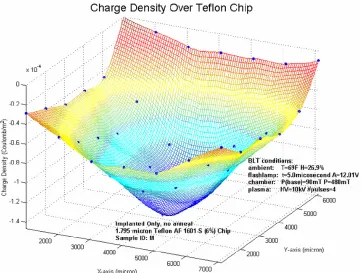
RIBOELECTRICFigure II-6.Triboelectrically charged Teflon chip
The resolution of Figure II-6 is not adequate to discern fine details. The time necessary to make this surface scan by hand is 10 minutes. Doubling the resolution for this scan would take 40 minutes to complete, and such a long and tedious scan is sure to increase operator error. A simple solution to this problem is to add a computer controlled x-y stage and read in the voltages using a GPIB device, which has since been implemented.
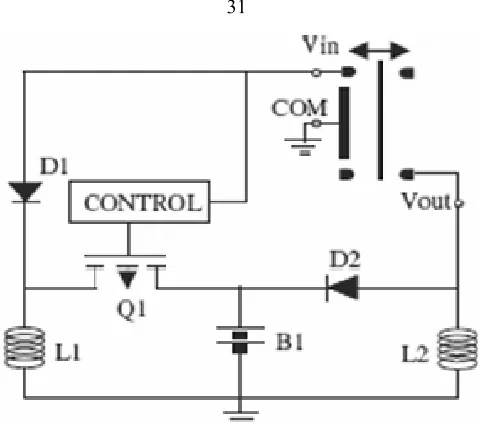
II.2.b.
B
ACKL
IGHTEDT
HYRATRON FORE
LECTRONB
EAMI
MPLANTATIONfield builds up inside the empty region. The field can be kept from breaking down on its own by choosing proper voltages and pressures in accordance with the Paschen curve. The proper operation point is at a helium pressure of 100-600mTorr and a voltage of 1-25kV.
When the thyratron is at the proper voltage and pressure, the UV flashlamp is pulsed, causing the copper inside the assembly produces electrons via the photoelectric effect. These electrons cause an avalanche effect as they are accelerated towards ground, creating a high density pocket of electrons. Once the pocket of electrons escapes the thyratron region, the electric field is no longer sufficient to maintain the avalanche. The process is repeatable in the time it takes to recharge the flashlamp, about 5 seconds. The result is a controlled, high density, pulsed, electron beam.
Care must be taken such that the applied voltage for a given helium concentration does not break down and generate plasma on its own. Although the majority of electrons produced by continuous plasma do not have significant electron implantation energy, a large transient pulse is generated at the start which is undesirable because the electron dose cannot be controlled. Implanting more electrons into the Teflon causes electric field breakdown inside the bulk of the material, which leads to lower total charge densities.
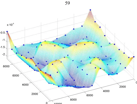
The high density pocket of electrons formed by the psuedospark forms a pulsed beam that is accelerated towards the ground plane. The beam spreads as it travels through space due to electron-electron repulsion. The cross-section of the electron beam is captured by a Teflon dielectric placed on the ground plane, which records the spatial distribution of charge. Figure II-7 is a plot of the spatial charge density, which appears as a 2-D Gaussian in the transverse directions. At higher voltages, the Gaussian is concentrated and the electrons have more kinetic energy.
The use of a BLT as an electron source is unique to the Caltech Micromachining Laboratory. It is utilized because of the high density of electrons, the speed of the electron implantation process, and the large acceleration voltage that allows electrons to be stored in deep traps where they will be stable for hundreds of years. Useful theoretical development on the lifetime of implanted charge can be found elsewhere[44].
[image:78.612.206.337.285.481.2]Also critical to the storage of charge is the electron implantation depth. The electrons must be located within the bulk of the dielectric material, or else they can easily be lost to surface conduction and humidity.
Figure II-8 Mean charge depth for corona charged FEP Teflon


![Figure I-7 Linear electromagnetic power generator developed by Perpetuum [15].](https://thumb-us.123doks.com/thumbv2/123dok_us/9416444.443578/42.612.144.400.164.377/figure-i-linear-electromagnetic-power-generator-developed-perpetuum.webp)
![Figure I-9 PMG0100 Evaluation Model [17]](https://thumb-us.123doks.com/thumbv2/123dok_us/9416444.443578/43.612.150.392.65.278/figure-i-pmg-evaluation-model.webp)