REFERENCE GUIDE
Windows API Guide
Reference
Volume 2
Version 3.0
c
o
N
T
Introduction 1
Document conventions ... 2
Part 3 General reference Chapter 7 Data types and structures 7 Data types ... 7
Data structures ... 9
BITMAP ... 10
Bitmap data structure ... 10
BITMAPCOREHEADER . . . .. 11
Device-independent bitmap format information ... 11
BITMAPCOREINFO ... 12
Device-independent bitmap informa tion ... 12
BITMAPFILEHEADER ... 14
Bitmap file information ... 14
BITMAPINFO . . . .. 14
~evice-i~dependent bitmap InformatIOn ... 14
BITMAPINFOHEADER ... 16
Device-independent bitmap format information ... 16
CLIENTCREATESTRUCT . . . .. 20
MDI client window creation structure . 20 COLORREF .. . . .. 20
Color specification ... 20
Palette-relative rgb ... 21
COMP AREITEMSTRUCT . . . .. 22
Owner-draw item-sorting information. 22 COMSTAT ... 23
Communication device status ... 23
CREATESTRUCT ... 24
Window-creation structure . . . .. 24
E
N
T
s
DCB ... 25Communications device control block . 25 DELETEITEMSTRUCT ... 28
Deleted owner-draw list-box item .... 28
DEVMODE ... 29
Printer driver initialization information ... 29
DLGTEMPLATE ... 32
Dialog template. . . .. 32
Header data structure ... 32
Font-information data structure . . . . .. 34
DRA WITEMSTRUCT ... 36
Owner-draw control drawing information ... 36
HANDLETABLE ... 38
Window-handle table ... 38
LOGBRUSH . . . .. 38
Logical-brush attribute information .. 38
LOGFONT ... 40
Logical-font descriptor ... 40
LOGP ALETTE ... 43
Logical color palette information ... 43
LOGPEN ... 44
Logical-pen attribute information .... 44
MDICREATESTRUCT ... 45
Mdi child window creation structure . 45 MEASUREITEMSTRUCT ... 46
Owner-draw control dimensions . . . .. 46
MENUITEMTEMPLATE ... 47
Menu-itemtemplate ... 47
METAFILEPICT ... 49
Metafile picture structure ... 49
MSG ... 50
Message data structure ... 50
Windows help key word table
structure . . . .. 50
OFSTRUCT ... 51
Open-file structure .. . . .. 51
P AINTSTRUCT . . . .. 52
WINDOWS paint information ... 52
P ALETTEENTRY ... 52
Logical palette color entry ... 52
POINT ... 54
Point data structure ... 54
RECT ... 54
Rectangle data structure ... 54
RGBQUAD ... 55
Rgb color structure . . . .. 55
RGBTRIPLE . . . .. 55
Rgb color structure . . . .. 55
TEXTMETRIC ... 56
Basic font metrics ... 56
WNDCLASS ... 58
Window class data structure . . . .. 58
Chapter 8 Resource script statements 61 Single-line statements ... 61
User-defined resources ... 63
Rcdata statement ... 64
Stringtable statement ... . . .. 65
Accelerators statement ... 67
Menu statement ... 68
Item-definition statements ... 70
MENUITEM ... 70
POPUP ... 71
MENUITEMSEPARATOR ... 73
DIALOG statement. . . .. 73
Dialog option statements . . . .. 75
STYLE ... 75
CAPTION ... 77
MENU ... 78
CLASS ... 78
FONT ... 79
Dialog control statements ... 79
LTEXT ... 80
RTEXT ... 81
CTEXT ... 82
CHECKBOX ... 83
PUSHBUTTON . . . .. 84
LISTBOX ... 85
GROUPBOX ... 86
DEFPUSHBUTTON ... 87
RADIOBUTTON . . . .. 88
EDITTEXT . . . .. 89
COMBO BOX . . . .. 91
ICON ... 92
SCROLL BAR . . . .. 93
CONTROL ... 94
Directives. . . .. 103
#include statement ... 103
#define statement ... 103
#Undef statement ... 104
#ifdef statement ... 104
#ifndef statement ... 105
#if statement ... 105
#elif statement ... 106
#else statement ... 106
#endif statement ... 107
Chapter 9 File formats 109 Bitmap file formats . . . .. 109
Icon resource file format ... 110
Cursor resource file format . . . .. 111
Clipboard file format ... 113
Metafile format ... 113
Metafile header . . . .. 114
Metafile records ... 115
Typical metafile record ... 116
Function-specific records. . . .. 116
AnimatePalette record 3.0 ... 117
BitBlt record (prior to 3.0) ... 117
BitBlt record 3.0 . . . .. 118
CreateBrushIndirect record. . . .. 118
CreateFontIndirect record . . . .. 119
CreatePalette record 3.0 . . . .. 119
CreatePatternBrush record (prior to 3.0) ... 119
CreatePatternBrush record 3.0 .... 120
Create region record ... 121
DeleteObject 3.0 ... 122
DrawText record ... 122
Escape record ... 122
ExtTextOut record ... 123
Polygon record ... 124
Poly Polygon record ... 124
Polyline record ... 125
SelectClipRegion ... 125
SelectObject ... 125
SelectPalette record 3.0 ... 126
SetDIBitsToDevice record 3.0 ... 126
SetPaletteEntries record 3.0 . . . .. 127
StretchBlt record (prior to 3.0) .... 127
StretchBlt record 3.0 ... 128
StretchDIBits record 3.0 .. . . .. 129
TextOut record ... 130
Sample metafile program output .... 130
Summary ... 132
Chapter 10 Module-definition statements 133 CODE ... 134
DATA ... 134
DESCRIPTION ... 135
EXETYPE ... 136
EXPORTS ... 136
HEAPSIZE . . . .. 137
IMPORTS .. .. . .. . .. . .. .. .. .. .. .. ... 138
LIBRARY ... 139
NAME ... 139
SEGMENTS .. . .. . .. . .. .. .. .. .. .. ... 140
STACKSIZE ... 141
STUB ... 141
Chapter 11 Binary and ternary raster-operation codes 143 Binary raster operations ... 143
Ternary raster operations ... 146
Chapter 12 Printer escapes 153 ABORTDOC ... 153
BANDINFO .. .. .. . . .. . .. . . .. . .. .... 154
BEGIN_PATH ... 156
CLIP _TO_PATH ... 157
DEVICE DATA ... 158
DRAFTMODE .. .. . .. . .. . . ... 158
DRAWPATTERNRECT ... 158
ENABLEDUPLEX . . . .. 160
ENABLEP AIRKERNING ... 160
ENABLERELATIVEWIDTHS ... 161
ENDDOC ... 162
END_PATH ... 162
ENUMPAPERBINS ... 164
ENUMPAPERMETRICS ... 165
EPSPRINTING ... 166
EXT_DEVICE_CAPS ... 166
EXTTEXTOUT ... 168
FLUSHOUTPUT .. . .. .. . . .. .. .. . . . .. 169
GETCOLORTABLE ... 169
GETEXTENDEDTEXTMETRICS ... 170
GETEXTENTT ABLE ... 173
GETFACENAME ... 174
GETPAIRKERNTABLE ... 174
GETPHYSPAGESIZE ... 176
GETPRINTINGOFFSET . . . .. 176
GETSCALINGFACTOR ... 176
GETSETP APERBINS ... 177
GETSETPAPERMETRICS ... 178
GETSETP APERORIENT ... . . . .. 179
GETSETSCREENPARAMS ... 180
GETTECHNOLOGY ... 181
GETTRACKKERNTABLE . . . .. 181
GETVECTORBRUSHSIZE ... 182
GETVECTORPENSIZE ... 183
MFCOMMENT . . . .. 183
NEWFRAME .. .. . .. . .. . .. . .. . . ... 184
NEXTBAND ... 184
PASSTHROUGH ... 185
QUERYESCSUPPORT . . . .. 186
RESTORE_CTM ... 186
SAVE_CTM ... 187
SELECTP APERSOURCE . . . .. 188
SETABORTPROC ... 188
SETALLJUSTV ALUES . . . .. 189
SET_ARC_DIRECTION . . . .. 190
SET_BOUNDS. . . .. 191 Using shared memory objects ... 208
SET_CLIP_BOX ... 192 Using clipboard formats ... 208
SETCOLORTABLE .. .. . . .. .. . .. .. . .. 193 U sing the System topic ... 208
SETCOPYCOUNT ... 194 DDE message directory . . . .. 209
SETKERNTRACK ... 195 WM_DDE_ACK ... 209
SETLINECAP ... 196 WM_DDE_ADVISE ... 211
SETLINE]OIN ... 196 WM_DDE_DATA ... 213
SET_MIRROR_MODE .. . . .. 197 WM_DDE_EXECUTE ... 214
SETMITERLIMIT ... 198 WM_DDE_INITIATE . . . .. 216
SET_POLY_MODE ... 199 WM_DDE_POKE ... 217
SET_SCREEN_ANGLE ... 201 WM_DDE_REQUEST ... 218
SET_SPREAD ... 201 WM_DDE_TERMINATE ... 219
STARTDOC . . . .. 202 WM_DDE_UNADVISE ... 219
TRANSFORM_CTM ... 203
Appendix A Virtual-key codes 221 Chapter 13 Windows DDE protocol definition 205 Using the DDE message set ... 206
T
A
B
L
E
s
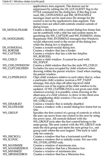
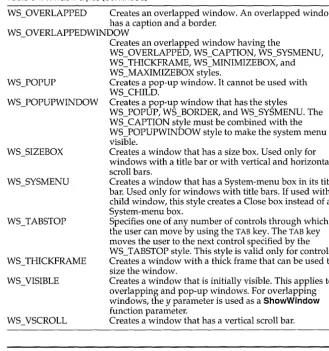
8.1: Window styles ... 75 11.2: Operation Indexes for PSo and
8.2: Control classes ... 94 DPSoo ... 146 8.3: Control styles ... 96 11.3: Raster-operation codes ... 147 9.1: Bit mask results ... 112 12.1: Meaning of BANDINFOSTRUCT 9.2: GDI functions and values ... 115 fields ... 155 11.1: Operation indexes for DPo and 13.1: DOE messages ... 206
N T R
o
Du
c
To
NThis manual gives the Windows-application developer general as well as detailed information about Windows functions, messages, data types, Resource Compiler statements, assembly language macros, and file formats. This manual provides detailed descriptions of each component of the Windows application program interface (API) for readers who already have a basic understanding of Windows programming. This manual is divided into two volumes. Volume 1 contains reference information describing the Windows functions and messages.
Volume 2 contains reference material for other components of the Windows API. It contains the following nine chapters and five appendixes:
Chapter 7, "Data types and structures," contains a table of data types and an alphabetical list of structures found in Windows.
Chapter 8, "Resource script statements," describes the statements that define resources which the Resource Compiler adds to an application's executable file. The statements are arranged according to functional groups.
Chapter 9, II File formats, II describes the formats of five types of files:
bitmap files, icon resource files, cursor resource files, clipboard files, and metafiles. Each description gives the general file structure and
information about specific parts of the file.
Chapter 10, "Module-definition statements, II describes the statements
contained in the module-definition file that defines the application's contents and system requirements for the LINK program.
Chapter 11, II Binary and ternary raster-operation codes, II describes the
raster operations used for line output and those used for bitmap output.
Chapter 13, "Windows DDE protocol definition," contains an alphabetical listing and description of the Windows messages that comprise the Windows Dynamic Data Exchange protocol.
Appendix A, "Virtual-key codes," lists the symbolic names and
hexadecimal values of Windows virtual-key codes and includes a brief description of each key.
Appendix B, "RC Diagnostic messages," contains a listing of Resource Compiler error messages and provides a brief description of each message.
Document conventions
Throughout this manual, the term ''~OS'' refers to both MS-DOS® and PC-DOS, except when noting features that are unique to one or the other. The following document conventions are used throughout this manual:
Convention Bold text
()
Italic text
Monospaced type
Description
Bold letters indicate a specific term or punctuation mark intended to be used literally: language key words or functions (such as EXETYPE or CreateWindow), DOS commands, and command-line options (such as /Zi). You must type these terms and punctuation marks exactly as shown. However, the use of uppercase or lowercase letters is not always significant. For instance, you can invoke the linker by typing either LINK, link, or Link at the DOS prompt.
In syntax statements, parentheses enclose one or more parameters that you pass to a function.
Words in italics indicate a placeholder; you are expected to provide the actual value. For example, the following syntax for the SetCursorPos function indicates that you must substitute values for the X and Y coordinates, separated by a comma:
SetCursorPos(X, Y)
Code examples are displayed in a nonproportional typeface.
Vertical ellipses in program examples
indicate that a portion of the program is omitted.
[[ ]]
{ }
horizontal ellipses indicate that you can specify more than one breakaddress for the 9 command:
9 [[=startaddress]] [[breakaddress]] ...
Double brackets enclose optional fields or parameters in command lines and syntax statements. In the following example, option and executable-file are optional parameters
of the RC command:
RC [[option]] filename [[executable-file]]
A vertical bar indicates that you may enter one of the entries shown on either side of the bar. The following command-line syntax illustrates the use of a vertical bar:
DB [[address I range]]
The bar indicates that following the DB (dump bytes) command, you can specify either an address or a range.
Curly braces indicate that you must specify one of the enclosed items.
SMALL CAPITAL LETTERS Small capital letters indicate the names of keys and key sequences, such as:
3.0
ALT + SPACEBAR
p
A
R
T
3
General reference
c
HData types
A p T E R
7
Data types and structures
This chapter describes the data types and structures used by Microsoft Windows functions and messages. It contains two parts: a table of data types and a list of Windows data structures, each arranged alphabetically.
The data types in the following list are key words that define the size and meaning of parameters and return values associated with Windows functions. This list contains character, integer, and Boolean types, pointer types, and handles. The character, integer, and Boolean types are common to most C compilers. Most of the pointer-type names begin with either a P prefix (for short pointers) or an LP prefix (for long pointers). A short pointer accesses data within the current data segment; a long pointer contains a 32-bit segment/offset value. A Windows application uses a handle to refer to a resource that has been loaded into memory. Windows provides access to these resources through internally maintained tables that contain individual entries for each handle. Each entry in the handle table contains the address of the resource and a means of identifying the resource type. The Windows data types are defined in the following list:
Data type
BOOl
BYTE char
Description
16-bit Boolean value. Unsigned 8-bit integer.
DWORD FAR FARPROC GLOBALHANDLE HANDLE HBITMAP HBRUSH HCURSOR HOC HFONT HICON HMENU HPALETTE HPEN HRGN HSTR int LOCALHANDLE long LONG LPBITMAP LPBITMAPCOREHEADER LPBITMAPCOREINFO LPBITMAPFILEHEADER LPBITMAPINFO LPBITMAPINFOHEADER LPCOMPAREITEMSTRUCT LPCREATESTRUCT
Unsigned 32-bit integer or a segment/offset address.
Data-type attribute that can be used to create a long pointer.
Long pointer to a function obtained by calling the MakeProclnstance function.
Handle to global memory. It is a 16-bit index to a block of memory allocated from the system's global heap.
General handle. It represents a 16-bit index to a table entry that identifies program data.
Handle to a physical bitmap. It is a 16-bit index to GDl's physical drawing objects.
Handle to a physical brush. It is a 16-bit index to GDl's physical drawing objects.
Handle to a cursor resource. It is a 16-bit index to a resource-table entry.
Handle to a display context. It is a 16-bit index to GDl's device-context tables.
Handle to a physical font. It is a 16-bit index to GDl's physical drawing objects.
Handle to an icon resource. It is a 16-bit index to a resource-table entry.
Handle to a menu resource. It is a 16-bit index to a resource-table entry.
Handle to a logical palette. It is a 16-bit index to GDl's physical drawing objects.
Handle to a physical pen. It is a 16-bit index to GDl's physical drawing objects.
Handle to a physical region. It is a 16-bit index to GDl's physical drawing objects.
Handle to a string resource. It is a 16-bit index to a resource-table entry.
Signed 16-bit integer.
Handle to local memory. It is a 16-bit index to a block of memory allocated from the application's local heap.
Signed 32-bit integer. Signed 32-bit integer.
Long pointer to a BITMAP data structure. Long pointer to a BITMAPCOREHEADER data structure.
Long pointer to a BITMAPCOREINFO data structure.
Long pointer to a BITMAPFILEHEADER data structure.
Long pointer to a BITMAPINFO data structure. Long pointer to a BITMAPINFOHEADER data structure.
Long pointer to a COMPAREITEMSTRUCT data structure.
LPDELETEITEMSTRUCT LPDRAWITEMSTRUCT LPHANDLETABLE LPINT LPLOGBRUSH LPLOGFONT LPLOGPALETIE LPLOGPEN LPMEASURBTEMSTRUCT LPMETAFILEPICT LPMSG LPOFSTRUCT LPPAINTSTRUCT LPPALETIEENTRY LPPOINT LPRECT LPRESOURCELIST LPSTR LPTEXTMETRIC LPVOID LPWNDCLASS NEAR NPSTR PINT PSTR PWORD short void WORD
Data structures
Long pointer to a DELETEITEMSTRUCT data structure.
Long pointer to a DRAWITEMSTRUCT data structure.
Long pointer to a HANDLETABLE data structure. Long pointer to a signed 16-bit integer.
Long pointer to a LOGBRUSH data structure. Long pointer to a LOGFONT data structure. Long pointer to a LOGPALETIe data structure. Long pointer to a LOG PEN data structure. Long pointer to a MEASUREITEMSTRUCT data structure.
Long pointer to a METAFILEPICT data structure. Long pointer to a MSG data structure.
Long pointer to an OFSTRUCT data structure. Long pointer to a PAINTSTRUCT data structure. Long pointer to a PALETIEENTRY data structure. Long pointer to a POINT data structure.
Long pointer to a RECT data structure.
Long pointer to one or more RESOURCESTRUCT data structures.
Long pointer to a character string.
Long pointer to a TEXTMETRIC data structure. Long pointer to an undefined data type. Long pointer to a WNDCLASS data structure. Data-type attribute that can be used to create a short pointer.
Near pointer to a character string. Pointer to a signed 16-bit integer. Pointer to a character string.
Pointer to an unsigned 16-bit integer. Signed 16-bit integer.
Empty value. It is used with a function to specify no return value.
Unsigned 16-bit integer.
BITMAP
BITMAP
Bitmap
data
structure
The BITMAP structure defines the height, width, color format, and bit values of a logical bitmap.
typedef struct tagBITMAP TBitmap = record
short bmType; bmType: Integer;
bmWidth: Integer; bmHeight: Integer; bmWidthBytes: Integer; bmPlanes: Byte; bmBitsPixel: Byte; bmBits: Pointer;
short bmWidth;
short bmHeight;
short bmWidthBytes;
BYTE bmPlanes;
BYTE bmBitsPixel;
LPSTR bmBits;
BITMAP; end;
The BITMAP structure has the following fields:
Field
bmType
bmWidth
bmHeight
bmWidthBytes
bmPlanes bmBitsPixel
bmBits
Description
Specifies the bitmap type. For logical bitmaps, the bmType field must be zero.
Specifies the width of the bitmap (in pixels). The width must be greater than zero.
Specifies the height of the bitmap (in raster lines). The height must be greater than zero.
Specifies the number of bytes in each raster line. This value must be an even number since the graphics device interface (GDI) assumes that the bit values of a bitmap form an array of integer (two-byte) values. In other words, bmWidthBytes 8 must be the next multiple of 16 greater than or equal to the bmWidth field.
Points to the number of color planes in the bitmap. Points to the number of adjacent color bits on each plane needed to define a pixel.
Points to the location of the bit values for the bitmap. The bmBits field must be a long pointer to an array of character (one-byte) values.
Comments The currently used bitmap formats are monochrome and color. The monochrome bitmap uses a one-bit, one-plane format. Each scan is a multiple of 16 bits.
Scans are organized as follows for a monochrome bitmap of height n:
Scan n-2 Scan n-l
BITMAP
The pixels on a monochrome device are either black or white. If the corresponding bit in the bitmap is 1, the pixel is turned on (white); if the corresponding bit in the bitmap is zero, the pixel is turned off (black). All devices that have the RC_BITBLT bit set in the device capabilities support bitmaps.
Each device has its own unique color format. In order to transfer a bitmap from one device to another, use GetDIBits and SetDIBits.
See also The CreateBitmaplndirect and GetObject functions in Chapter 4, "Functions directory," in Reference, Volume 1.
BITMAPCOREHEADER
3.0
Device-independent
bitmap
format
information
The BITMAPCOREHEADER structure contains information about the dimensions and color format of a device-independent bitmap that is compatible with Microsoft OS/2 Presentation Manager versions 1.1 and 1.2 bitmaps.
typedef struct tagBITMAPCOREHEADER {
DWORD bcSize;
TBitmapCoreHeader = record bcSize: Longint;{ used to get to
color table }
WORD bcWidth;
WORD bcHeight;
WORD bcPlanes;
WORD bcBitCount;
} BITMAPCOREHEADER;
bcWidth: Word; bcHeight: Word; bcP lanes: Word; bcBitCount: Word; end;
The BITMAPCOREHEADER structure has the following fields:
Field bcSize bcWidth bcHeight bcPlanes bcBitCount
Description
Specifies the number of bytes required by the BITMAp·
COREHEADER structure.
Specifies the width of the bitmap in pixels. Specifies the height of the bitmap in pixels.
Specifies the number of planes for the target device and must be set to 1.
BITMAPCOREHEADER
Comments The BITMAPCOREINFO data structure combines the
BITMAPCOREHEADER structure and a color table to provide a complete definition of the dimensions and colors of a device-independent bitmap. See the description of the BITMAPCOREINFO data structure for more information about specifying a device-independent bitmap.
An application should use the information stored in the bcSize field to locate the color table in a BITMAPCOREINFO data structure with a method such as the following:
pColor = ((LPSTR) pBitmapCoreInfo + (WORD) (pBitmapCoreInfo
-» bcSize))
BITMAPCOREINFO
3.0
Device-independent
bitmap
information
The BITMAPCOREINFO structure fully defines the dimensions and color information for a device-independent bitmap that is compatible with Microsoft OS/2 Presentation Manager versions 1.1 and 1.2 bitmaps.
typedef struct _BITMAPCOREINFO { BITMAPCOREHEADER bmciHeader; RGBTRIPLE
TBitmapCoreInfo = record bmciHeader: TBitmapCoreHeader; bmciColors: array[O .. O] of
TRGBTriple; bmciColors [] ;
} BI TMAP CORE INFO; end;
The BITMAPCOREINFO structure contains the following fields:
Field bmciHeader bmciColors
Description
Specifies a BITMAPCOREHEADER data structure that contains information about the dimensions and color format of a device-independent bitmap.
Specifies an array of RGBTRIPLE data structures that define the colors in the bitmap.
BITMAPCOREINFO
The bcBitCount field of the BITMAPCOREHEADER structure determines the number of bits which define each pixel and the maximum number of colors in the bitmap. This field may be set to any of the following values:
Value
1
4
.8
24
Description
The bitmap is monochrome, and the bmciColors field must contain two entries. Each bit in the bitmap array represents a pixel. If the bit is clear, the pixel is displayed with the color of the first entry in the bmciColors table; if the bit is set, the pixel has the color of the second entry in the table.
The bitmap has a maximum of 16 colors, and the bmciColors field contains 16 entries. Each pixel in the bitmap is represented by a four-bit index into the color table. For example, if the first byte in the bitmap is Ox1F, then the byte represents two pixels. The first pixel contains the color in the second table entry, and the second pixel contains the color in the 16th table entry.
The bitmap has a maximum of 256 colors, and the bmciColors field contains 256 entries. In this case, each byte in the array represents a single pixel.
The bitmap has a maximum of 224 colors. The bmciColors field is NULL, and each three bytes in the bitmap array represents the relative intensities oired, green, and blue, respectively, of a pixel.
The colors in the bmciColors table should appear in order of importance. Alternatively, for functions that use device-independent bitmaps, the
bmciColors field can be an array of 16-bit unsigned integers that specify an index into the currently realized logical palette instead of explicit RGB values. In this case, an application using the bitmap must call device-independent bitmap functions with the wUsage parameter set to DIB_PAL_COLORS.
_ The bmciColors field should not contain palette indexes if the bitmap is to be stored in a file or transferred to another application. Unless the
BITMAPFILEHEADER
BITMAPFILEHEADER
3.0
Bitmap file
information
Comments
BITMAPINFO
Device-independent
bitmap
information
The BITMAPFILEHEADER data structure contains information about the type, size, and layout of a device-independent bitmap (DIB) file.
typedef struct tagBITMAPFILEHEADER { WORD bfType;
TBitrnapFileHeader = record bfType: Word;
DWORD bfSize;
WORD bfReservedl;
WORD bfReserved2;
DWORD bfOffBits;
bfSize: Longint; bfReservedl: Word; bfReserved2: Word; bfOffBits: Longint;
} BITMAPFILEHEADER; end;
The BITMAPFILEHEADER data structure contains the following fields:
Field Description
Specifies the type of file. It must be BM. Specifies the size in DWORDs of the file. Is reserved and must be set to zero. Is reserved and must be set to zero.
bfType bfSize bfReserved1 bfReserved2
bfOffBits Specifies in bytes the offset from the BITMAPFILEHEADER of the actual bitmap in the file.
A BITMAPINFO or BITMAPCOREINFO data structure immediately follows the BITMAPFILEHEADER structure in the DIB file.
3.0
The BITMAPINFO structure fully defines the dimensions and color information for a Windows 3.0 device-independent bitmap.
typedef struct tagBITMAPINFO {
BITMAPINFOHEADER brniHeader;
RGBQUAD brniColors[l];
} BITMAP INFO;
TBitrnapInfo = record
brniHeader: TBitrnapInfoHeader; brniColors: array[O .. O] of TRGBQuad; end;
Field
bmiHeader
bmiColors
BITMAPINFO
Description
Specifies a BITMAPINFOHEADER data structure that contains
information about the dimensions and color format of a device-independent bitmap.
Specifies an array of RGBQUAD data structures that define the colors in the bitmap.
Comments A Windows 3.0 device-independent bitmap consists of two distinct parts: a BITMAPINFO data structure that describes the dimensions and colors of the bitmap, and an array of bytes that define the pixels of the bitmap. The bits in the array are packed together, but each scan line must be zero-padded to end on a LONG boundary. Segment boundaries can appear anywhere in the bitmap, however. The origin of the bitmap is the lower-left corner.
The biBitCount field of the BITMAPINFOHEADER structure determines the number of bits which define each pixel and the maximum number of colors in the bitmap. This field may be set to any of the following values:
Value
1
4
8
24
Description
The bitmap is monochrome, and the bmiColors field must contain two
entries. Each bit in the bitmap array represents a pixel. If the bit is clear, the pixel is displayed with the color of the first entry in the
bmiColors table; if the bit is set, the pixel has the color of the second entry in the table.
The bitmap has a maximum of 16 colors, and the bmiColors field
contains up to 16 entries. Each pixel in the bitmap is represented by a four-bit index into the color table. For example, if the first byte in the bitmap is Ox1F, then the byte represents two pixels. The first pixel contains the color in the second table entry, and the second pixel contains the color in the 16th table entry.
The bitmap has a maximum of 256 colors, and the bmiColors field
contains up to 256 entries. In this case, each byte in the array represents a single pixel.
The bitmap has a maximum of 224 colors. The bmiColors field is NULL, and each three bytes in the bitmap array represents the relative intensities of red, green, and blue, respectively, of a pixel.
The biClrUsed field of the BITMAPINFOHEADER structure specifies the number of color indexes in the color table actually used by the bitmap. If
the biClrUsed field is set to 0, the bitmap uses the maximum number of colors corresponding to the value of the biBitCount field.
The colors in the bmiColors table should appear in order of importance. Alternatively, for functions that use device-independent bitmaps, the
BITMAPINFO
index into the currently realized logical palette instead of explicit RGB values. In this case, an application using the bitmap must call device-independent bitmap functions with the wUsage parameter set to DIB_PAL_COLORS.
. . The bmiColors field should not contain palette indices if the bitmap is to be stored in a file or transferred to another application. Unless the application uses the bitmap exclusively and under its complete control, the bitmap color table should contain explicit RGB values.
BITMAPINFOHEADER
3.0
Device-independent
bitmap
format
information
The BITMAPINFOHEADER structure contains information about the dimensions and color format of a Windows 3.0 device-independent bitmap.
typedef struct tagBITMAPINFOHEADER{ DWORD biSize;
TBitmaplnfoHeader = record biSize: Longint;
DWORD biWidth; biWidth: Longint;
biHeight: Longint; biPlanes: Word; biBitCount: Word; biCompression: Longint; biSizelmage: Longint; biXPelsPerMeter: Longint; biYPelsPerMeter: Longint; biClrUsed: Longint; biClrlmportant: Longint; DWORD biHeight;
WORD biPlanes;
WORD biB it Count DWORD biCompression; DWORD biSizelmage; DWORD biXPelsPerMeter; DWORD biYPelsPerMeter; DWORD biClrUsed; DWORD biClrlmportant;
BITMAPINFOHEADER; end;
The BITMAPINFOHEADER structure has the following fields:
Field biSize biWidth biHeight biPlanes biBitCount
Description
Specifies the number of bytes required by the BITMAp· INFOHEADER structure.
Specifies the width of the bitmap in pixels. Specifies the height of the bitmap in pixels.
Specifies the number of planes for the target device and must be set to 1.
Specifies the number of bits per pixel. This value must be 1,4,
biCompression
biSizelmage biXPelsPerMeter
biYPelsPerMeter
biClrUsed
biClrlmportant
BITMAPINFOHEADER
Specifies the type of compression for a compressed bitmap. It can be one of the following values:.
Value Description
BCRGB Specifies that the bitmap is not compressed.
BCRLE8 Specifies a run-length encoded format for bitmaps with 8 bits per pixel. The compression format is a two-byte format consisting of a count byte followed by a byte containing a color index. See the following "Comments" section for more information.
BCRLE4 Specifies a run-length encoded format for bitmaps with 4 bits per pixel. The compression format is a two-byte format consisting of a count byte followed by two word-length color indexes. See the following "Comments" section for more information.
Specifies the size in bytes of the image.
Specifies the horizontal resolution in pixels per meter of the target device for the bitmap. An application can use this value to select a bitmap from a resource group that best matches the characteristics of the current device.
Specifies the vertical resolution in pixels per meter of the target device for the bitmap.
Specifies the number of color indexes in the color table actually used by the bitmap. If this value is 0, the bitmap uses the maximum number of colors corresponding to the value of the biBitCount field. See the description of the BITMAPINFO
data structure earlier in this chapter for more information on the maximum sizes of the color table. If biClrUsed is nonzero, then the biClrUsed field specifies the actual number of colors which the graphics engine or device driver will access if the
biBitCount field is less than 24. If the biBitCount field is set to 24, the biClrUsed field specifies the size of the reference color table used to optimize performance of Windows color palettes. If the bitmap is a "packed" bitmap (that is, a bitmap in which the bitmap array immediately follows the
BITMAP FINO header and which is referenced by a single pointer), the biClrUsed field must be set to 0 or to the actual size of the color table.
Specifies the number of color indexes that are considered important for displaying the bitmap. If this value is 0, then all colors are important.
Comments The BITMAPINFO data structure combines the BITMAPINFOHEADER
structure and a color table to provide a complete definition of the
BITMAPINFOHEADER
An application should use the information stored in the biSize field to locate the color table in a BITMAPINFO data structure with a method such as the following:
pCo1or = ((LPSTR) pBitmaplnfo + (WORD) (pBitmaplnfo -» biSize))
Bitmap compression formats
Windows supports formats for compressing bitmaps that define their colors with 8 bits per pixel and with 4 bits per pixel. Compression reduces the disk and memory storage required for the bitmap. The following paragraphs describe these formats.
When the biCompression field is set to BCRLE8, the bitmap is
compressed using a run-length encoding format for an 8-bit bitmap. This format may be compressed in either of two modes:
II Encoded
1'1 Absolute
Both modes can occur anywhere throughout a single bitmap.
Encoded mode consists of two bytes: the first byte specifies the number of consecutive pixels to be drawn using the color index contained in the second byte. In addition, the first byte of the pair can be set to zero to indicate an escape that denotes an end of line, end of bitmap, or a delta. The interpretation of the escape depends on the value of the second byte of the pair. The following list shows the meaning of the second byte:
Second Byte
Of Escape Meaning
a
End of line.1 End of bitmap.
2 Delta. The two bytes following the escape contain unsigned values indicating the horizontal and vertical offset of the next pixel from the current position.
Absolute mode is signalled by the first byte set to zero and the second byte set to a value between 03H and FFH. In absolute mode, the second byte represents the number of bytes which follow, each of which contains the color index of a single pixel. When the second byte is set to 2 or less, the escape has the same meaning as in encoded mode. In absolute mode, each run must be aligned on a word boundary.
The following example shows the hexadecimal values of an 8-bit compressed bitmap:
BITMAPINFOHEADER
02 78 00 00 09 IE 00 01
This bitmap would expand as follows (two-digit values represent a color index for a single pixel):
04 04 04 06 06 06 06 06 45 56 67 78 78
move current position 5 right and 1 down 78 78
end of line
IE IE IE IE IE IE IE IE IE end of RLE bitmap
When the biCompression field is set to BI_RLE4, the bitmap is
compressed using a run-length encoding format for a 4-bit bitmap, which also uses encoded and absolute modes. In encoded mode, the first byte of the pair contains the number of pixels to be drawn using the color indexes in the second byte. The second byte contains two color indexes, one in its high-order nibble (that is, its low-order four bits) and one in its low-order nibble. The first of the pixels is drawn using the color specified by the high-order nibble, the second is drawn using the color in the low-order nibble, the third is drawn with the color in the high-order nibble, and so on, until all the pixels specified by the first byte have been drawn.
In absolute mode, the first byte contains zero, the second byte contains the number of color indexes that follow, and subsequent bytes contain color indexes in their high- and low-order nibbles, one color index for each pixel. In absolute mode, each run must be aligned on a word boundary. The end-of-line, end-of-bitmap, and delta escapes also apply to BCRLE4. The following example shows the hexadecimal values of a 4-bit
compressed bitmap:
03 04 05 06 00 06 45 56 67 00 04 78 00 02 05 01 04 78 00 00 09 IE 00 01
This bitmap would expand as follows (single-digit values represent a color index for a single pixel):
040 06060 455 667 787 8
move current position 5 right and 1 down 787 8
CLiENTCREATESTRUCT
CLiENTCREATESTRUCT
3.0
MDI client
window
creation
structure
COLORREF
Color
The CLiENTCREATESTRUCT data structure contains information about the menu and first multiple document interface (MDI) child window of an MDI client window. An application passes a long pointer to this structure as the IpParam parameter of the CreateWindow function when creating an MDI client window.
typedef struct tagCLIENTCREATESTRUCT
{
TClientCreateStruct = record hWindowMenu: THandle; idFirstChild: Word;
HMENU hWindowMenu;
WORD idFirstChild; end;
} CLIENTCREATESTRUCT;
The CLiENTCREATESTRUCT structure contains the following fields: Field
hWindowMenu
idFirstChild
Description
Is the menu handle of the application's Window menu. An application can retrieve this handle from the MDI frame window's menu using the GetSubMenu function. Is the child window ID of the first MDI child window created. Windows increments the ID for each additional MDI child window that the application creates, and reassigns identifiers when the application destroys a window to keep the range of identifiers continuous. These identifiers are used in WM_ COMMAND messages to the application's MDI frame window when a child window is selected from the Window menu, and should not conflict with any other command identifiers.
specification
A COLORREF color value is a long integer that specifies a color. GDI functions that require a color (such as CreatePen and FloodFiII) accept aCOLORREF value as a parameter. Depending on how an application uses the COLORREF value, the value has three distinct forms. It may specify any of the following:
• Explicit values for red, green, and blue (RGB) • An index into a logical color palette
COLORREF
TColorRef = Longint;
ExpJict RGB When specifying an explicit RGB value, the COLORREF value has the following hexadecimal form:
OxOObbggrr
The low-order byte contains a value for the relative intensity of red; the second byte contains a value for green, and the third byte contains a value for blue. The high-order byte must be zero. The maximum value for a single byte is FF (hexadecimal). The following list illustrates the hexadecimal values that produce the indicated colors.
Value
OxOOOOOOFF OxOOOOFFOO OxOOFFOOOO OxOOOOOOOO OxOOFFFFFF Ox00808080
Color
Pure red Pure green Pure blue
Black White
Medium gray
The RGB macro accepts values for red, green, and blue, and returns an explicit RGB COLORREF value.
PaleHe index When specifying an index into a logical color palette, the COLORREF
value has the following hexadecimal form:
Palette-Ox0100iiii
The two low-order bytes consist of a 16-bit integer specifying an index into a logical palette. The third byte is not used and must be zero. The fourth (high-order) byte must be set to l.
For example, the hexadecimal value Ox01000000 specifies the color in the palette entry of index 0; Ox0100000C specifies the color in the entry of index 12, and so on.
The PALETTEINDEX macro accepts an integer representing an index into a logical palette and returns a palette-index COLORREF value.
relative rgb
When specifying a palette-relative RGB value, the COLORREF value has the following hexadecimal form:Ox02bbggrr
COLORREF
For output devices that support logical palettes, Windows matches a palette-relative RGB value to the nearest color in the logical palette of the device context, as though the application had specified an index to that palette entry. If an output device does not support a system palette, then Windows uses the palette-relative RGB as though it were an explict RGB
COLOR REF value.
The PALETTERGB macro accepts values for red, green, and blue, and returns a palette-relative RGB COLORREF value.
Comments Before passing a palette-index or palette-relative RGB COLORREF value to a function that also requires a device-context parameter, an application that uses its own palette must select its palette into the device context (by calling the SelectPalette function) and realize the palette (by calling
RealizePalette). This ensures that the function will use the correct palette-entry color. For functions that create an object (such as CreatePen), the application must select and realize the palette before selecting the object for the device context.
COMPAREITEMSTRUCT
3.0
Owner-draw
item-sorting
information
The COMPAREITEMSTRUCT structure supplies the identifiers and application-supplied data for two items in a sorted owner-draw combo box or list box.
Whenever an application adds a new item to an owner-draw combo or list box created with the CBS_SORT or LBS_SORT style, Windows sends the owner a WM_ COMP ARE ITEM message. The IParam parameter of the message contains a long pointer to a COMPAREITEMSTRUCT data structure. When the owner receives the message, the owner compares the two items and returns a value indicating which item sorts before the other. For more information, see the description of the WM_COMPAREITEM message in Chapter 6, "Messages directory," in Reference, Volume 1.
typedef struct tagCOMPAREITEMSTRUCT WORD CtlType;
WORD CtlID;
HWND hwndItem;
WORD itemID1; DWORD itemDatal; WORD i temID2; DWORD itemData2; COMPAREITEMSTRUCT;
TCompareltemStruct = record
CO MSTAT
Communi-cation
device
status
COMPAREITEMSTRUCT
The COMPAREITEMSTRUCT structure has the following fields:
Field
CtlType
CtIID hwndltem itemlD1
itemData1
itemlD2
itemData2
Description
Is ODT_LISTBOX (which specifies an owner-draw list box) or ODT_COMBOBOX (which specifies an owner-draw combo box).
Is the control ID for the list box or combo box. Is the window handle of the control.
Is the index of the first item in the list box or combo box being compared.
Is application-supplied data for the first item being
compared. This value was passed as the IParam parameter of the message that added the item to the combo or list box. Is the index of the second item in the list box or combo box being compared.
Is application-supplied data for the second item being compared. This value was passed as the IParam parameter of the message that added the item to the combo or list box.
The COMSTAT structure contains information about a communications device.
typedef struct tagCOMSTAT BYTE fCtsHold: 1; BYTE fDsrHold: 1; BYTE fRlsdHold: 1; BYTE fXoffHold: 1; BYTE fXoffSent: 1; BYTE fEof: 1; BYTE fTxim: 1; WORD cblnQue; WORD cbOutQue; COMSTAT;
TComStat = record
Flags: Byte; cblnQue: Word; cbOutQue: Word; end;
The COMSTAT structure has the following fields:
Field Description
fCtsHold: 1 Specifies whether transmission is waiting for the clear-to-send (CTS) signal to be sent.
fDsrHold: 1 Specifies whether transmission is waiting for the data-set-ready (DSR) signal to be sent.
CO MSTAT
fXoffHold: 1
fXoffSent: 1
fEof: 1 fTxim: 1 cblnQue cbOutQue
Specifies whether transmission is waiting as a result of the XoffChar character being received.
Specifies whether transmission is waiting as a result of the XoffChar character being transmitted. Transmission halts when the XoffChar character is transmitted and used by systems that take the next character as XON, regardless of the
actual character. ' '
Specifies whether the EofChar character has been received. Specifies whether a character is waiting to be transmitted. Specifies the number of characters in the receive queue. Specifies the number of characters in the transmit queue.
See also The GetCommError function in Chapter 4, "Functions directory," in Reference, Volume 1.
CREATESTRUCT
Window-creation
structure
The CREATESTRUCT structure defines the initialization parameters passed to an application's window function.
typedef struet tagCREATESTRUCT
LPSTR lpCreateParams;
HANDLE hInstanee; HANDLE hMenu;
HWND hwndParent;
int ey;
int ex;
int y;
int x;
long style;
LPSTR lpszName;
LPSTR lpszClass;
long ExStyle;
CREATESTRUCT;
TCreateStruet = record lpCreateParams: PChar; hInstanee: THandle; hMenu: THandle; hwndParent: HWnd; ey: Integer; ex: Integer; y: Integer; x: Integer; style: LongInt; lpszName: PChar; lpszClass: PChar; dwExStyle: Longint; end;
The CREATESTRUCT structure has the follpwing fields:
Field IpCreateParams hlnstance hMenu hwndParent cy Description
Points to data to be used for creating the window. Identifies the module-instance handle of the module that owns the new window.
Identifies the menu to be used by the new window.
Identifies the window that owns the new window. This field is NULL if the new window is a top-level window.
DCB
Communi-cations
device
control
block
ex y x CREATESTRUCTSpecifies the width of the new window.
Specifies the y-coordinate of the upper-left corner of the new window. Coordinates are relative to the parent window if the new window is a child window. Otherwise, the coordinates are relative to the screen origin.
Specifies the x-coordinate of the upper-left corner of the new window. Coordinates are relative to the parent window if the new window is a child window. Otherwise, the coordinates are relative to the screen origin.
style IpszName
Specifies the new window's style.
Points to a null-terminated character string that specifies the new window's name.
IpszClass Points to a null-terminated character string that specifies the new window's class name.
ExStyle Specifies extended style for the new window.
The DeB structure defines the control setting for a serial communications device.
typedef struct tagDCB BYTE Id;
WORD BaudRate; BYTE ByteSize; BYTE Parity; BYTE StopBits; WORD RlsTimeout; WORD CtsTimeout; WORD DsrTimeout;
BYTE fBinary: 1; BYTE fRtsDisable: BYTE fParity: 1; BYTE fOutxCtsFlow: BYTE fOutxDsrFlow: BYTE fDummy: 2; BYTE fDtrDisable:
BYTE fOutX: 1; BYTE fInX: 1; BYTE fpeChar: 1; BYTE fNull: 1; BYTE fChEvt: 1; BYTE fDtrflow: 1; BYTE fRtsflow: 1;
1;
1 ;
1;
1;
TDCB = record
Id: Byte; BaudRate: Word; ByteSize: Byte; Parity: Byte; StopBits: Byte; RlsTimeout: Word; CtsTimeout: Word; DsrTimeout: Word; Flags: Word; XonChar: Char; XoffChar: Char; XonLim: Word; XoffLim: Word; PeChar: Char; EofChar: Char; EvtChar: Char; TxDelay: Word;
DeB
BYTE fDumrny2: 1;
char XonChar; char XoffChar; WORD XonLim; WORD XoffLim; char PeChar; char EofChar; char EvtChar; WORD TxDelay; DCB;
The DeB structure has the following fields:
Field
Id
BaudRate
ByteSize
Parity
StopBits
RlsTimeout
CtsTimeout
DsrTimeout
fBinary: 1
fRtsDisable: 1
Description
Specifies the communication device. This value is set by the device driver. If the most significant bit is set, then the DCB
structure is for a parallel device.
Specifies the baud rate at which the communications device operates.
Specifies the number of bits in the characters transmitted and received. The ByteSize field can be any number from 4 to 8. Specifies the parity scheme to be used. The Parity field can be anyone of the following values:
Value Meaning
EVENP ARITY Even
MARKPARITY Mark
NOPARITY No parity
ODDPARITY Odd
SP ACEP ARITY Space
Specifies the number of stop bits to be used. The StopBits
field can be anyone of the following values:
Value Meaning
ONESTOPBIT 1 stop bit
ONE5STOPBITS 1.5 stop bits
TWOSTOPBITS 2 stop bits
Specifies the maximum amount of time (in milliseconds) the device should wait for the receive-line-signal-detect (RLSD) signal. (RLSD is also known as the carrier detect (CD) signal.) Specifies the maximum amount of time (in milliseconds) the device should wait for the c1ear-to-send (CTS) signal. Specifies the maximum amount of time (in milliseconds) the device should wait for the data-set-ready (DSR) signal.
Specifies binary mode. In nonbinary mode, the EofChar
character is recognized on input and remembered as the end of data.
fParity: 1
fOutxCtsFlow: 1
fOutxDsrFlow: 1
fDummy: 2 fDtrDisable: 1
fOutX: 1
flnX: 1
fPeChar: 1
fNull: 1 fChEvt: 1
fDtrflow: 1
fRtsflow: 1
fdummy2: 1 XonChar
XoffChar
XonLim
XoffLim
DeB
remains low. If fRtsDisable is clear, RTS is sent when the device is opened and turned off when the device is closed. Specifies whether parity checking is enabled. If the fParity
field is set, parity checking is performed and errors are reported.
Specifies that clear-to-send (CTS) signal is to be monitored for output flow control. If the fOutxCtsFlow field is set and CTS is turned off, output is suspended until CTS is again sent. Specifies that the data-set-ready (DSR) signal is to be monitored for output flow control. If the fOutxDsrFlow field is set and DSR is turned off, output is suspended until DSR is again sent.
Reserved.
Specifies whether the data-terminal-ready (DTR) signal is disabled. If the fDtrDisable field is set, DTR is not used and remains low. If fDtrDisable is clear, DTR is sent when the device is opened and turned off when the device is closed. Specifies that XON jXOFF flow control is used during transmission. If the fOutX field is set, transmission stops when the XoffChar character is received, and starts again when the XonChar character is received.
Specifies that XON jXOFF flow control is used during reception. If the flnX field is set, the XonChar character is sent
when the receive queue comes within XoffLim characters of
being full, and the XonChar character is sent when the
receive queue comes within XonLim characters of being
empty.
Specifies that characters received with parity errors are to be replaced with the character specified by the fPeChar field. The fParity field must be set for the replacement to occur. Specifies that received null characters are to be discarded. Specifies that reception of the EvtChar character is to be flagged as an event.
Specifies that the data-terminal-ready (DTR) signal is to be used for receive flow control. If the fDtrflow field is set, DTR
is turned off when the receive queue comes within XoffLim
characters of being full, and sent when the receive queue
comes within XonLim characters of being empty.
Specifies that the ready-to-send (RTS) signal is to be used for receive flow control. If the fRtsflow field is set, RTS is turned
off when the receive queue comes within XoffLim characters
of being full, and sent when the receive queue comes within
XonLim characters of being empty. Reserved.
Specifies the value of the XON character for both transmission and reception.
Specifies the value of the XOFF character for both transmission and reception.
Specifies the minimum number of characters allowed in the receive queue before the XON character is sent.
DeB
PeChar EofChar EvtChar TxDelay
value is subtracted from the size of the receive queue (in bytes) to calculate the maximum number of characters allowed.
Specifies the value of the character used to replace characters received with a parity error.
Specifies the value of the character used to signal the end of data.
Specifies the value of the character used to signal an event. Not currently used.
See also The BuildCommDCB, GetCommState, and SetCommState functions in Chapter 4, "Functions directory," in Reference, Volume 1.
DELETEITEMSTRUCT
3.0
Deleted
owner-draw
list-box item
The DELETEITEMSTRUCT structure describes a deleted owner-draw list-box or combo-list-box item. When an item is removed from the list list-box or combo box, or when the list box or combo box is destroyed, Windows sends the WM_DELETEITEM message to the owner for each deleted item; the IParam parameter of the message contains a pointer to this structure.
typedef struct tagDELETEITEMSTRUCT
{
TDeleteltemStruct = record CtlType: Word;
WORD CtlType
WORD CtlID;
WORD itemID;
HWND hwndltem;
DWORD itemData;
DELETEITEMSTRUCT;
CtlID: Word; itemID: Word; hwndItem: HWnd; itemData: Longint; end;
The DELETEITEMSTRUCT structure has the following fields: Field
CtlType CtllD itemlD hwndltem item Data
Description
Is ODT_LISTBOX (which specifies an owner-draw list box) or ODT_COMBOBOX (which specifies an owner-draw combo box). Is the control ID for the list box or combo box.
Is the index of the item in the list box or combo box being removed.
Is the window handle of the control.
Contains the value passed to the control in the IParam parameter of the LB _INSERTSTRING, LB_ADDSTRING,
DEVMODE
Printer driver
initialization
information
DEVMODE3.0
The DEVMODE data structure contains information about the device initialization and environment of a printer driver. An application passes this structure to the DeviceCapabilities and ExtDeviceMode functions.
typedef struct _devicemode { TDevMode = record
dmDeviceName:
char dmDeviceName[32];
WORD dmSpecVersion;
WORD dmDriverVersion;
WORD WORD DWORD short short short short short short short short short short BYTE dmSize; dmDriverExtra; dmFields; dmOrientation; dmPaperSize; dmPaperLength; dmPaperWidth; dmScale; dmCopies; dmDefaultSource; dmPrintQuality; dmColor; dmDuplex;
array[O .. cchDeviceName-l] of Char; dmSpecVersion: Word;
dmDriverVersion: Word; dmSize: Word;
dmDriverExtra: Word; dmFields: LongInt; dmOrientation: Integer; dmPaperSize: Integer; dmPaperLength: Integer; dmPaperWidth: Integer; dmScale: Integer; dmCopies: Integer; dmDefaultSource: Integer; dmPrintQuality: Integer; dmColor: Integer; dmDuplex: Integer; dmDriverData[dmDriverExtra];
} DEVMODE;
end;
The DEVMODE structure contains the following fields:
Field dmDeviceName dmSpecVersion dmDriverVersion dmSize Description
Specifies the name of the device the driver supports; for example, "PCL/HP LaserJet" in the case of PCL/HP® LaserJet®. This string is unique among device drivers. Specifies the version number of the initialization data specification upon which the structure is based. The version number follows the Windows version number and is currently Ox300.
Specifies the printer driver version number assigned by the printer driver developer.
DEVMODE
dmDriverExtra
dmFields
dmOrientation
dmPaperSize
dm PaperLength
dmPaperWidth
dmScale
dmCopies
dmDefaultSource
Contains the size of the dmDriverData field and is the
length of the device-specific data in the DEVMODE
structure. If an application does not use device-specific information, it should set this field to zero.
Is a bitfield that specifies which of the remaining fields in the DEVMODE structure have been initialized. Bit 0 (defined as DM_ORIENTATION) corresponds to
dmOrientation; bit 1 (defined as DM_P APERSIZE) specifies dmPaperSize, and so on. A printer driver supports only those fields that are appropriate for the printer technology.
Selects the orientation of the paper. It can be either
DMORIENT _PORTRAIT (1) or
DMORIENT _LANDSCAPE (2).
Selects the size of the paper to print on. This field may be set to zero if the length and width of the paper are both set
by the dmPaperLength and dmPaperWidth fields.
Otherwise, the dmPaperSize field can be set to one of the following predefined values:
Value Meaning
DMPAPER_LETTER B/2-by-ll-inch paper
DMPAPER_LEGAL B/2-by-14-inch paper
DMPAPER_A4 210-by-297-millimeter paper
DMPAPER_CSHEET 17-by-22-inch paper
DMP APER_DSHEET 22-by-34-inch paper
DMPAPER_ESHEET 34-by-44-inch paper
DMPAPER_ENV _9 3/B-by-B/B-inch #9 envelope
DMPAPER_ENV _10 4/B-by-9/5-inch #10 envelope
DMPAPER_ENV _11 4/2-by-1O/B-inch #11 envelope
DMPAPER_ENV_12 4/4-by-ll-inch#12 envelope
DMPAPER_ENV _14 5-by-11/2-inch #14 envelope
Overrides the length of the paper specified by the
dmPaperSize field, either for custom paper sizes or for devices such as dot-matrix printers which can print on a page of arbitrary length. These values, along with all other values which specify a physical length, are in tenths of a millimeter.
Overrides the width of the paper specified by the
dmPaperSize field.
Scales the printed output. The apparent page size is scaled by a factor of dmScale/lOO from the physical page size. A letter-size paper with a dmScale value of 50 would appear to be 17 by 22 inches, and output text and graphics would be correspondingly half their normal height and width. Selects the number of copies printed if the device supports multiple-page copies.
dmPrintQuality
dmColor
dmDuplex
dmDriverData[ ]
IJ DMBIN_DEF AULT
IJ DMBIN_UPPER
IJ DMBIN_LOWER
IJ DMBIN_MANUAL
IJ DMBIN_TRACTOR
IJ DMBIN_ENVELOPE
DEVMODE
There is also a range of values reserved for device-specific bins. The GETSETP APERBINS and ENUMP APERBINS escapes use these indexes to be consistent with
initialization information.
Specifies the printer resolution. There are four predefined device-independent values:
IJ DMRES_HIGH (-4)
IJ DMRES_MEDIUM (-3)
IJ DMRES_LOW (-2)
IJ DMRES_DRAFT (-1)
If a positive value is given, it specifies the number of dots per inch (DP!) and is therefore device dependent. Switches between color and monochrome on color printers. Possible values are:
IJ DMCOLOR_COLOR (1)
IJ DMCOLOR_MONOCHROME (2).
Selects duplex or double-sided printing for printers capable of duplex printing. Values for this field include:
IJ DMDUP_SIMPLEX (1)
IJ DMDUP _HORIZONTAL (2)
IJ DMDUP _VERTICAL (3).
Contains device-specific data defined by the device driver.
Comments Only drivers fully updated for Windows version 3.0 and which export the
DLGTEMPLATE
DLGTEMPLATE
Dialog
template
Header
data
structure
The DLGTEMPLATE defines the contents of a dialog box. This structure is divided into three distinct parts:
Part Description
Header Data Structure Font-Information Data Structure List of Items
Contains a general description of the dialog box.
Defines the font with which text is drawn in the dialog box. This part is optional.
Describes the parts that compose the dialog box.
The CreateDialoglndirect, CreateDialoglndirectParam, DialogBoxlndirect,
and DialogBoxlndirectParam functions use this structure.
The DLGTEMPLATE header is shown here:
typedef struct { long dtStyle; BYTE dtltemCount; int dtX; int dtY;
int dtCX;
int dtCY;
char dtMenuName[]; char dtClassName[]; char dtCaptionText[]; DLGTEMPLATE;
The DLGTEMPLATE header has the following fields:
Field
dtStyle
Description
Specifies the style of the dialog box. This field may be any or all of these values:
Value
DS_LOCALEDIT
Meaning
Specifies that text storage for edit controls will be allocated in the application's local data segment. This allows the use of the EM_ GETHANDLE and
DS_MODALFRAME
DS_ABSALIGN
DS_NOIDLEMSG
DLGTEMPLATE
this style is not specified, edit-control data is located in a separate global data block. Specifies a system-modal dialog box.
Specifies a dialog box with a modal dialog-box border. This style can be combined with the WS_CAPTION and
WS_SYSMENU style flags to create a dialog box with a title bar and System menu.
Indicates that dtX and dtY are relative to the screen origin, not to the owner of the dialog box. Specifies that a font other than the system font is to be used to draw text in the dialog box. If this flag is set, the FONTINFO data structure described in the following paragraphs must immediately
follow the DLGTEMPLATE header.
When Windows creates a dialog box with this attribute, Windows sends the WM_SETFONT message to the dialog-box window prior to creating the controls.
Specifies that Windows will not send the WM_ENTERIDLE message to the owner of the dialog box while the dialog box is displayed.
dtitemCount Specifies the number of items in the dialog box. A dialog box can contain up to 255 controls.
dtX Specifies the x-coordinate of the upper-left corner of the
dialog box in units of /4 of the current dialog base width unit. The dialog base units are computed from the height and
width of the current system font; the GetDialogBaseUnits
function returns the current dialog base units in pixels. Unless DS_ABSALIGN is set in the dtStyle field, this value is relative to the origin of the parent window's client area.
dtY Specifies the y-coordinate of the upper-left corner of the
dialog box in units of /8 of the current dialog base height unit. Unless DS_ABSALIGN is set in the dtStyle field, this value is relative to the origin of the parent window's client area.
dtCX Specifies the width of the dialog box in units of /4 of the dialog base width unit.
DLGTEMPLATE
dtMenuName[ ]
dtClassName[ ]
dtCaptionText[ ]
Specifies a null-terminated string that specifies the name of the dialog box's menu. If this field is NULL, the dialog-box window does not have a menu.
Specifies a null-terminated string that supplies the name of the dialog box's class. If dtClassName[ ] is zero, it creates a dialog box with the standard dialog-box style. If an
application specifies a class name, it should provide a dialog procedure that processes each dialog-box message directly or calls the DefDlgProc function to process the message. Also, the application must register the class with the cbWndExtra field of the WNDCLASS data structure set to
DLGWINDOWEXTRA.
Specifies a null-terminated string that supplies the caption for the dialog box. .
Font-information
data
structure
The FONTINFO data structure contains information about the point size and face name of the font which Windows is to use to draw text in the dialog box.
PointSize; typedef struct{
short int char FONTINFO;
szTypeFace[); /* A null-terminated string */
The FONTINFO structure has the following fields:
Field Description
PointSize szTypeFace
Specifies the size of the typeface in points.
Specifies the name of the typeface; for example, "Courier".
Comments The font specified must have been previously loaded, either from WIN.INI or explicitly by calling the LoadFont function.
Item list The item list consists of one or more DLGITEMTEMPLATE data structures, one for each control in the dialog box. The first such structure
immediately follows the FONTINFO structure or the header at the first byte after the terminating null character in the szTypeFace field or the
dtCaptionText[ ] field. The following shows the format of the
DLGITEMTEMPLATE structure.
typedef struct {
int dtilX;
int dtilY;