International Conference on Renewable Energies and Power Quality (ICREPQ’17) Malaga (Spain), 4th to 6th April, 2017
exÇxãtuÄx XÇxÜzç tÇw cÉãxÜ dâtÄ|àç ]ÉâÜÇtÄ(RE&PQJ) ISSN 2172-038 X, No.15 April 2017
Design of an Appliance Switch Responding to Solar Energy
Ambalika Pradip Koshti 1, Dr. Arthur Williams 1
1
Department of Electronics and Electrical Engineering, University of Nottingham, UK.
Phone no.: +44 115 846 8684; +91 7709585782 Email: [email protected] Email: [email protected]
Abstract:
Knowing the ill effects of dependence upon conventional resources for generation of energy, the world is already making an effort to harness energy from renewable energy sources. However, the use of conventional resources is not fully eliminated from daily lives of people as the renewable energy sources are limited due to their intermittent nature.The paper presents a unique technique of Demand Side Management (DSM) for a domestic consumer whose house is equipped with on-grid solar PV panel system. DSM is the management of energy needs according to its availability. The paper deals with designing of an automated switch which is an adapter and can be inserted into standard 13amp socket. The adapter is equipped with a sensor that transmits data to it. The smart solar switch can detect surplus power generated by the PV system and it controls non-priority loads in the house depending upon the amount of surplus power. The designed switch provides an automatic, fast, easy to install and safe option for customers who want to increase their use of solar energy. Its performance was tested in a lab setup as well as in real time scenario in a home.
Key words:
Demand Side Management (DSM), Homeautomation system, Export power, Wireless communication, PV panels
1. Introduction
Utilisation of electrical energy is key to economic growth and improvement in people’s living standards. On the other hand, ever growing demand of energy throughout the globe leads to some serious issues, eg. CO2
emissions, which need urgent concern[1]. Renewable energy sources can substitute conventional sources however, their intermittent nature is a barrier to their wider uptake.
One approach to increase the use of renewable energy is called Demand Side Management (DSM). With reference to a smart grid, demand side management refers to the possibility of dynamically controlling and scheduling energy consumption [2]. Demand side management includes shifting of loads from a low generation period to a high generation period. Thus it maximises the use of available energy rather than increasing the generation. DSM techniques can be broadly classified into two categories, ie. centralised and de-centralised. Centralised techniques need collection of data centrally and hence usually remove control from the consumer [3]. De-centralised techniques, one of which is described in this paper, operate within a single home or customer. The aim is to manage energy consumption of appliances within the vicinity of a single consumer’s electricity supply and hence this approach does not necessarily include communication with the grid.
In a grid connected PV system, a consumer can use grid electricity when the electricity generated by the panels is not sufficient to meet demand and can export it into the grid if the panels generate surplus energy. However, it is usually advantageous to use the generated energy at home as much as possible rather than exporting it into grid. This is because the additional revenue to the household due to export of power is lower than the cost of buying electricity from the grid. In the case of the UK, where a Feed in Tariff (FiT) is paid to consumers who have a grid-connected solar PV system, the additional revenue for exported power is effectively zero. This is because FiT payments are based on a generation meter (rather than an export meter) and export payments are based on a fixed (nominal) 50% of generation. Even in other countries, where FiT is based on export, the cost of buying power from the supply company may be greater than the rate paid for export.
shift loads to improve utilisation. The difficulty of improving utilisation can result in customer’s apathy towards the use of resources as it seems inconvenient from the user’s point of view to keep record of instantaneous power generation and switch appliances on manually.
This paper presents a unique home automation system to apply DSM for domestic consumers whose houses are equipped with grid-connected PV panels. The design consists of an appliance switch that automatically responds to the availability of electricity generated from PV panels, which is a novel system for household DSM.
2. Review of existing de-centralised DSM units
The idea of maximizing use of capacity from intermittent renewable energy is not a new one, although the device described in this paper has several unique features. Some of the commercially available methods were researched before design was carried out. Some ideas in research papers that were also reviewed.
One product that has been available in the UK is known as ImmerSun (T1060) [4]. This is an automatic controller to maximise the use of green energy, which is mostly used with domestic PV systems. It monitors the electricity which is about to be exported to the grid and diverts it to an electric water heater. It uses a chopper circuit with a solid-state switch to control the immersion heater current, and so directs any surplus electricity generated from renewable sources to the heater in the hot water cylinder. Two disadvantages of this system are its relatively high cost and limited application. With the wider use of condensing combi boilers for hot water heating, many homes no longer have a hot water cylinder.
An interesting remote switching product named Belkin WeMo switch [5] was also investigated. The WeMo switch is connected with a home Wi-Fi and should be plugged with devices that are needed to be switched. It works with a free app which can be installed on smart phones or tablets. The app runs on mobile internet allowing customers to turn on/off their electronic appliances through the phone even if they are away from the home. The app also allows to schedule the devices as per customer choice, but it does not have the capability to detect spare solar capacity.
Shenzhen Sailwider Co. Ltd. manufactures a 2-way home energy monitoring and control system [6]. The system displays the balance between energy consumption and energy production from PV panels. The system consists of a transmitter with current clamp, a controller unit with a display and sensor plugs. It allows the user to set automatic switching for targeted appliances to the threshold balance value between energy consumption and energy production and consumption. The controller receives information about energy consumption of the devices plugged in to sensor plugs, and the current clamp for solar energy production. The controller also has
buttons to remotely switch on/off the devices. This system can be used to carry out the same function as the one described later, but it is much more complex and is likely only to be used by someone interested in energy consumption and monitoring.
A similar energy monitoring system is manufactured by “enagage.efergy” know as Engage Solar[7]. The system consists of two clamps one to be connected to a live feed wire and other one to a wire coming out of a solar inverter, with transmitters and an engage hub. These transmitters wirelessly send data to the hub which is connected to internet router via Ethernet cable. The web platform or app shows the energy consumption on devices such as computers, tabs or smart phones, enabling the consumer to remotely switch on loads when there is spare solar PV. However, there is no automatic capability to switch on an appliance when there is spare PV capacity. Thus there is still a place for a simple device to switch a specific appliance on, based on surplus PV capacity.
Other devices are described in research papers, for example by Cabrera et al.[8] which presents a method to maximise the use of the solar energy to power an air conditioning unit for low voltage consumers. The authors have developed a home energy management system (HEMS) in which the air conditioning unit was controlled according to the availability of solar radiation and the desirable inside temperature. The algorithm considered house and PV panels as a thermodynamic model. The HEMS receives metrological data for a day from the nearest weather forecasting station in terms of ambient temperature and solar irradiation. An advantage of this method is the GUI which allows users to input the desired temperature of a house and view key data. However, the model calculates PV power output based on the data from the weather forecasting station which may be some distance from the house. It does not consider the factors like inclination angle or shadows, so is unlikely to predict output power accurately with changes in local weather.
In another paper, by Boynuegri et. al [9], a system was proposed for a house equipped with solar PV panels, wind turbines and battery banks along with all electric inhome appliances and a power grid connection. An algorithm is suggested that monitors the state of charge (SoC) of the batteries which were charged from renewable energy sources only. Electrical loads were divided into two categories as critical loads and
non-critical loads. Usually, this type of division is done so as to avoid any discomfort
to customers. To monitor and manage devices, commercially available smart plugs were used. These plugs are able to communicate with a central computer through Zigbee protocol. However, the system is limited in application to houses with battery storage.
by a smart scheduler based on each device’s time of use probabilities and real time energy prices. It was assumed that the energy price would vary every hour. The smart meter autonomously learns the energy consumption pattern of each appliance under different weather conditions. A concept of load clustering was used so as to group the appliances which were expected to be switched on in same time slot. It then schedules loads based on price and priority information, and also responds to consumer requests. It demonstrates how a smart scheduler can be good option as a DSM technique for domestic consumers.
A similar system is proposed by Tascikaraoglu et al. [11] using a fuzzy logic-based controller to determine the appropriate load shifting and rescheduling operations with renewable sources. However, as in [9] a power forecasting approach was implemented, which has significant limitations.
3. Smart Solar Switch Description and
Working
Having looked at commercial and research ideas, the overall design of the smart solar switch unit was developed. The aim was to produce a relatively simple and low-cost system that would be able to switch a given low-priority appliance to make use of the lower (or zero) cost power during times of solar surplus. A key objective of the design was to provide a simple plug and play approach which could avoid any complications related to installation.
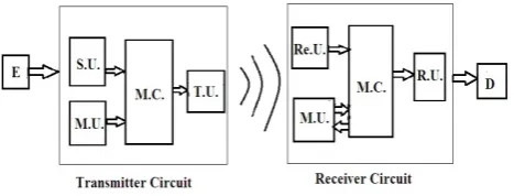
[image:3.595.49.283.496.585.2]The smart solar switch system has two distinct circuits- a transmitter circuit and a receiver circuit as shown in Figure 1. Both circuits are built around an Arduino Uno microcontroller (M.C.).
Fig. 1: Structure of Smart Solar Switch
The transmitter circuit contains a sensing unit (S.U.), a measuring unit (M.U.) and a transmitter unit (T.U.). To use the export power at any time, it is necessary to detect surplus power generation. The sensing unit must be able to sense the power level at the grid connection, and also have some method to detect the direction of that power – whether importing or exporting.
Energy companies prohibit any interference with the installed meter. To avoid any requirement to interfere with any mains cables, it was a prime objective to design a parallel system which could sense the export of power without going inside of the meter or consumer unit. A
standard consumer electricity meter contains a flashing LED which can be used to detect the direction of power flow. During power consumption, the LED flashes at a rate proportional to the imported power, but when exporting, the LED glows continuously. A phototransistor in the sensing unit detects light from the LED and feeds a signal to the microcontroller through a comparator circuit. Initially a photodiode was employed, but this was found to lack the current output needed to switch the microprocessor, given the relatively low light level of the meter LED.
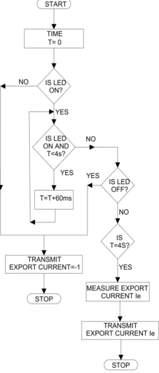
The phototransistor in the sensing unit needs to be placed in front of the meter LED and should be properly aligned with the LED to avoid interference of external light. The phototransistor and comparator circuit checks the status of the LED after every 60ms for a period of 4s. If the LED glows continuously during this period then the microcontroller produces a command to measure a value of export current.The on period of pulses generated from electricity meter is 50ms [12]. Hence, the status is checked after every 60ms.
The magnitude of the power flow is measured at the transmitter side by a current clamp fitted around a live wire coming to the electricity meter from the grid. There is no voltage measurement at the transmitter end, it only has the current clamp, which can be fitted by the consumer. The output of the current clamp was calibrated using a standard clamp meter. On receiving the command from the microcontroller, the clamp measures an instantaneous value of export current. This measured value is fed back to the microcontroller through a signal conditioning circuit. This circuit is necessary as the Uno board can only receive DC values. The value of export current (Ie) is sent to the receiver side by the transmitter
unit. A pair of RF transmitter and receiver of a frequency range of 433MHz is used for communication. This transmitter circuit is powered by a standard 9V dc power supply plugged into the mains, but could also be powered by a 9V battery.
Only current measurement is done at the electricity meter. As the voltage at all plugs in a house is approximately constant, current consumption can be used to estimate power flow, assuming stable power factor. Therefore, only current values are compared by the microcontroller.
The receiver circuit is divided into three parts (Fig.1) - a receiver unit (Re.U.), measuring unit (M.U.) and a relay unit (R.U.). This receiver circuit is provided with a push button. When a new device is connected to the smart switch, the button should be pressed for approximately 5s. This is all that needs to be done when connecting a new device. The push button runs an interrupt service routine (ISR) to measure power consumption of the newly connected device. The measuring unit records values of voltage, current and power factor along with the power value. The receiver side microcontroller stores a value which is 1.1 times the recorded current value as the device current (ID). The receiver unit receives the
stored ID value and if it is equal to or more than ID then
[image:4.595.329.526.62.409.2]the connected device will be turned on.
Figure 2 explains the algorithm of the transmitter circuit. When there is import of electricity from the grid, Ie is set
to -1.
Fig. 2: Transmitter End Flowchart
An issue with the control system is that if a device of say rated power P were connected and the transmitter unit detects power P being exported, then it would switch on the appliance using all of the surplus power so there would no longer be export. The device would then switch off, allowing P to be exported again and the control system would then go into an oscillation with the appliance being switched on and off at each cycle of the algorithm. Hence, the 10% allowance is added to ID to
provide necessary hysteresis to the control loop.
The receiver side program needs to take into account the appliance on/off state in its algorithm, hence it checks the state of the connected device before making a power comparison. Figure 3 indicates the sequence of commands at the receiver circuit.
Fig. 3: Receiver End Flowchart
3. Results and Discussion
The smart solar switch can be used with non-priority loads such as clothes dryer, heaters of low power rating, cooling fans etc. Two aspects were taken into consideration while testing the functionality of the plug - time response and measurement accuracy. The switch takes 4-5 seconds to turn on the appliance once the export of power is detected. This may seem a slow response but this time delay is necessary to avoid any false switching. On the other hand, in the absence of sufficient power, the device will be turned off instantaneously to avoid grid electricity consumption. The appliance circuit is switched using a relay, which is housed in a box (see Fig.5).
[image:4.595.70.230.131.505.2]Figure 4. The transmitter circuit under test.
Figure 5. The receiver circuit under test with a small fan heater as load.
Later the smart solar switch was tested in a house with a 3.9 kW grid-connected PV system. In this case the transmitter circuit was disconnected from the PC and placed near the meter, so that the current clamp could be correctly installed. The receiver circuit was placed in an upstairs room and used to switch a 300 W clothes dryer, or when more than 1 kW was available, a fan heater was connected.
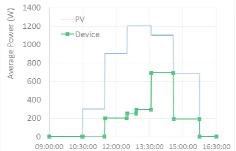
Figure 6. House test: average PV generation and device load throughout the daytime on a sunny January day.
Tests in the house showed that even in the winter, during a sunny day (when external temperature was below 5 °C) the smart solar switch could provide some extra use of the available solar power to provide background heat (Fig. 6). Not all of the PV could be used for the device because other loads (lights, computers, heating pump, an iron) were connected, using around 300 W on average.
During the period from 10.30 to 15.45, no power was imported from the grid. Obviously in summer months there is a much larger surplus from the PV system that could be put to use.
4. Conclusion
The smart solar switch provides a simple, easy to install and fully automatic solution to utilise surplus solar energy instantaneously. It is simpler to install than the immersion switch device available in the market, which needs to be hard wired into the AC mains voltage circuit [6]. It is also simpler and cheaper than other devices that are linked to an energy monitor unit, yet require the user to set the threshold power level. The total cost of components for the prototype was less than €45 and could be reduced with batch production. The smart solar switch provides a user friendly plug and play approach unlike other switches described in literature [13,14] which require a lot of involvement from customers. The user has flexibility to plug in various devices.
The phototransistor must be properly aligned with the meter LED to detect its light. A better system to fit this is required. Also, the longer-term reliability of the measuring units and relay needs to be tested. For further development towards a commercial device, the circuits could be made much smaller so that they are more easily installed. As a next stage it is hoped to be able to test it in social housing in Nottingham. Across the city, there are around 4000 houses let by City Homes that have solar PV installed. The occupiers are able to use the generated electricity to offset their energy costs, while City Homes collects the feed-in tariff. With the smart solar switch, occupiers would be able to make better use of their free renewable energy.
Acknowledgement
The authors would like to acknowledge the contribution to the research from two colleagues: Alex Ottway, from the Technical Support Team, who built the receiver box, and Dr Richard Davies, who helped set up the lab testing.
References
[1] Electricity Production in the World: General Forecast, 2013- Chapter 1 available at
www.energiesrenouvelables.org/observer/html/inventaire/ pdf/15e-inventaire-Chap01Eng.pdf
[2] Daniele Miorandi and Francesco De Pellegrini, “Demand-side management in smart grids: An evolutionary games perspective,”in Performance Evaluation Methodologies and Tools (VALUETOOLS), 6th Int. Conf., Cargese, Oct. 2012,pp 178-187.
[3] Thilliainathan Logenthiran, Dipti Srinivasan, Tan Zong Shun, “DSM in Smart Grid Using Heuristic Optimization”, in IEEE Transactions on Smart Grids,2012, Vol. 3, pp.1244-1252.
[4] https://www.immersun.co.uk/product/ accessed 12
Jan 2017
[5] https://store.stormfront.co.uk/belkin-wemo-switch
[image:5.595.49.286.505.656.2][6] http://sailwider-smartpower.com/eco/home-solar-pv-generator-monitor-control-system-hot/ accessed 12 Jan 2017
[7] http://efergy.com/ accessed 12 Jan 2017
[8] Ana K. Cabrera, Hasan Ul Banna, Cosmin Koch-Ciobotarus, Siddharta Ghosh, “Optimization of an air conditioning unit according to renewable energy availability and user's comfort”, in IEEE PES Innovative Smart Grid Technologies, Europe, Conf.at Istanbul, Oct. 2014, pp 1-7.
[9] A. Rifat Boynuegri, Bunyamin Yagcitekin, Mustafa Baysal, Arif Karakas, Mehmet Uzunoglu, “Energy management algorithm for smart home with renewable energy
sources,” in Power Engineering, Energy and Electrical Drives (POWERENG),4th Int. Conf., Istanbul, May 2013, pp 1753-1758.
[10]Christopher O. Adika and Lingfeng Wang, "Autonomous Scheduling for Household Energy Management,” in IEEE Transt. On Smart Grid, vol. 5, Aug. 2013,pp 673-682.
[11]A. Tascikaraoglu, A.R. Boynuegri, M. Uzunoglu, “A Demand Side Management Strategy Based on Forecasting of Residential Renewable Sources: A Smart House System In Turkey,” Energy and Buildings, vol.80, Elsevier, Sept 2014, pp 309-320.
[12] Educational Article available at
http://reuk.co.uk/Directory/index.htm
[13]Sanjaya Kumar Nayak, N.C.Sahoo, G. Panda, “Demand side management of residential loads in a smart grid using 2D particle swarm optimization technique”, in IEEE Power, Communication and Information Technology Conference (PCITC),Conf. at Bhubaneshwar, Oct. 2015, pp 201-206.