A&A 567, A51 (2014)
DOI:10.1051/0004-6361/201322534 c
ESO 2014
Astronomy
&
Astrophysics
Constraining the structure of the transition disk HD 135344B
(SAO 206462) by simultaneous modeling of multiwavelength
gas and dust observations
?,??,???
A. Carmona
1, C. Pinte
2,1, W. F. Thi
1, M. Benisty
1, F. Ménard
2,1, C. Grady
3,4,5, I. Kamp
6, P. Woitke
7, J. Olofsson
8,
A. Roberge
5, S. Brittain
9, G. Duchêne
10,1, G. Meeus
11, C. Martin-Zaïdi
1, B. Dent
12,
J. B. Le Bouquin
1, and J. P. Berger
13,11 UJF-Grenoble 1/CNRS-INSU, Institut de Planétologie et d’Astrophysique de Grenoble (IPAG) UMR 5274, 38041 Grenoble,
France
e-mail:[email protected]
2 UMI-FCA, CNRS/INSU France (UMI 3386), and Departamento de Astronomía, Universidad de Chile, 36D Casila, Santiago,
Chile
3 Eureka Scientific, 2452 Delmer, Suite 100, Oakland CA 96002, USA
4 ExoPlanets and Stellar Astrophysics Laboratory, Code 667, Goddard Space Flight Center, Greenbelt MD 20771, USA 5 Goddard Center for Astrobiology, Goddard Space Flight Center, Greenbelt MD 20771, USA
6 Kapteyn Astronomical Institute, PO Box 800, 9700 AV Groningen, The Netherlands
7 SUPA, School of Physics and Astronomy, University of St Andrews, St Andrews KY16 9SS, UK 8 Max Planck Institut für Astronomie, Königstuhl 17, 69117 Heidelberg, Germany
9 Department of Physics & Astronomy, 118 Kinard Laboratory, Clemson University, Clemson SC 29634, USA 10 Astronomy Department, University of California, Berkeley CA 94720-3411, USA
11 Departamento de Física Teórica, Universidad Autonoma de Madrid, Campus Cantoblanco, 28049 Madrid, Spain 12 Joint ALMA Observatory, Alonso de Córdova 3107, 763-0355 Vitacura, Santiago, Chile
13 European Southern Observatory, Alonso de Córdova, 3107 Vitacura, Chile
Received 25 August 2013/Accepted 23 March 2014
ABSTRACT
Context.Constraining the gas and dust disk structure of transition disks, particularly in the inner dust cavity, is a crucial step to-ward understanding the link between them and planet formation. HD 135344B is an accreting (pre-)transition disk that displays the CO 4.7µm emission extending tens of AU inside its 30 AU dust cavity.
Aims.We constrain HD 135344B’s disk structure from multi-instrument gas and dust observations.
Methods.We used the dust radiative transfer code MCFOST and the thermochemical code ProDiMo to derive the disk structure from the simultaneous modeling of the spectral energy distribution (SED), VLT/CRIRES CO P(10) 4.75µm,Herschel/PACS [O
] 63µm, Spitzer/IRS, and JCMT12COJ=3−2 spectra, VLTI/PIONIERH-band visibilities, and constraints from (sub-)mm continuum inter-ferometry and near-IR imaging.Results.We found a disk model able to describe the current gas and dust observations simultaneously. This disk has the following structure. (1) To simultaneously reproduce the SED, the near-IR interferometry data, and the CO ro-vibrational emission, refractory grains (we suggest carbon) are present inside the silicate sublimation radius (0.08<R<0.2 AU). (2) The dust cavity (R<30 AU) is filled with gas, the surface density of the gas inside the cavity must increase with radius to fit the CO ro-vibrational line profile, a small gap of a few AU in the gas distribution is compatible with current data, and a large gap of tens of AU in the gas does not appear likely. (4) The gas-to-dust ratio inside the cavity is>100 to account for the 870µm continuum upper limit and the CO P(10) line flux. (5) The gas-to-dust ratio in the outer disk (30<R<200 AU) is<10 to simultaneously describe the [O
] 63µm line flux and the CO P(10) line profile. (6) In the outer disk, most of the gas and dust mass should be located in the midplane, and a significant fraction of the dust should be in large grains.Conclusions.Simultaneous modeling of the gas and dust is required to break the model degeneracies and constrain the disk structure. An increasing gas surface density with radius in the inner cavity echoes the effect of a migrating jovian planet in the disk structure. The low gas mass (a few Jupiter masses) throughout the HD 135344B disk supports the idea that it is an evolved disk that has already lost a large portion of its mass.
Key words.protoplanetary disks – stars: pre-main sequence – planets and satellites: formation – techniques: high angular resolution –
techniques: interferometric – stars: individual: HD 135344B (SAO 206462)
? Based on PIONIER, CRIRES, and UVES observations collected at
the VLTI and VLT (European Southern Observatory, Paranal, Chile) with programs 087.C-0702(A,B,D), 087.C-0458(C), 087.C-0703(B), 179.C-0151(A), 077.C-0521(A).
??
Herschel is an ESA space observatory with science instruments provided by European-led Principal Investigator consortia and with im-portant participation from NASA.
??? Appendix A is available in electronic form at
http://www.aanda.org
1. Introduction
Observations of young stars of different ages reveal that pro-toplanetary disks evolve from optically thick, gas-rich disks to optically thin, gas-poor debris disks (e.g., see review by Williams & Cieza 2011). The transition between these two classes of objects is believed to occur relatively fast (105years)
compared to the disk’s life time (5−10 Myr) (e.g.,Cieza et al.
2007; Damjanov et al. 2007; Currie & Sicilia-Aguilar 2011).
Infrared space observatories have unveiled several young stars with spectral energy distributions (SED) characterized by IR-excess at>10µm and significantly reduced excesses at shorter wavelengths (e.g., Strom et al. 1989; Calvet et al. 2005; Sicilia-Aguilar et al. 2006;Hernández et al. 2006;Espaillat et al. 2007; Fang et al. 2009;Merín et al. 2010; Rebull et al. 2010; Cieza et al. 2010). These sources are commonly named “tran-sition disks”, because they are believed to be the objects in the transition phase between a young star with an optically thick gas-rich disk and a star with an optically thin gas-poor debris disk.
Generally, the lack of strong emission in the near or mid-IR SED is interpreted as evidence of a gap or cavity from a few up to tens of AU in the disk. Follow-up imaging of several transition disks with sub-mm interferometers have confirmed that transi-tion disks indeed have a deficit of sub-mm continuum emission at a few mJy levels inside tens of AU (e.g.,Piétu et al. 2007; Brown et al. 2009; Hughes et al. 2009; Andrews et al. 2011; Isella et al. 2012), thus providing further evidence for such inner disk cavities, at least on the large dust grains.
Several scenarios have been discussed in the literature to explain the presence of a cavity and the transitional disk SED shape: grain growth (e.g.,Dullemond & Dominik 2005;Birnstiel et al. 2012), migrating giant planets that opened a gap (e.g., Varnière et al. 2006;Zhu et al. 2011;Dodson-Robinson & Salyk 2011), dust filtration by a giant planet (e.g.,Rice et al. 2006;Zhu et al. 2012;Pinilla et al. 2012), disk dissipation due to a photo-evaporative disk wind (e.g.,Alexander & Armitage 2007;Owen et al. 2012), and dust free inner holes due to radiation pressure (Chiang & Murray-Clay 2007). One important step toward un-derstanding the transitional disk phenomenon is to understand how the gas and dust structures compare. Do they follow each other in density structure? Do they thermally de-couple? Does the gas-to-dust ratio stay constant as a function of the radius?
Several young stars with transition disks are emission-line stars that exhibit signs of accretion (e.g., Najita et al. 2007b; Muzerolle et al. 2010;Cieza et al. 2012). As a consequence, the cavities imaged in the sub-mm should have gas as the material from the optically thick outer disk flows through the cavity to be accreted by the central object (e.g.,Lubow & D’Angelo 2006). In fact, several transition disks display emission of CO at 4.7µm (e.g.,Salyk et al. 2009) a common tracer of warm gas in the inner disk (e.g.,Najita et al. 2007a). Furthermore, in a few transition disks, CO ro-vibrational emission has been spatially resolved up to distances of tens of AU (Pontoppidan et al. 2008). Moreover, recent studies of dust-scattered light in the near-IR have detected emission from small dust grains inside the cavities that were pre-viously imaged with sub-mm interferometry, with the additional and remarkable property that no sharp edge is seen at the loca-tion of the sub-mm cavity’s inner radius (e.g.Muto et al. 2012; Garufi et al. 2013). This suggests that what is observed is likely a change in the dust size distribution inside the cavity (Dong et al. 2012). Near-IR interferometry provides evidence of dust emission (and inhomogeneities) inside the dust cavity of transi-tion disks (e.g.,Kraus et al. 2013). Furthermore, recent ALMA observations have spatially resolved gas inside the cavity of tran-sition disks (Casassus et al. 2013;Bruderer et al. 2013).
In summary, the observational evidence indicating that the dust cavities of transitions disks are indeednot emptyhas been
steadily growing during past years. This opens interesting ques-tions such as how much gas and dust are present in the cavity; what is their distribution and chemical composition; if dust is present, what is its size distribution; if there is a gap in the gas or in the dust, how large is it?
The goal of this paper is to address the problem of the gas and dust structures in transition disks by performing a detailed study of the transition disk HD 135344B (SAO 206462). Our aim is to constrain the disk structure by modeling simultaneously and in a coherent way multiwavelength & multi-instrument gas and dust observations of the inner and the outer disk. Most specifically, we investigate gas and dust disk content and struc-ture inside the cavity by simultaneously modeling the SED, new VLTI-PIONIER near-IR interferometry data, the CO 4.7 µm emission, and constraints from sub-mm continuum interferom-etry. Furthermore, we seek to constrain the gas mass and the gas-to-dust ratio in the outer disk by employing the SED, the [O
] 63µm and 145µm lines, and (sub-)mm observations.HD 135344B is an accreting (2×10⁻⁸ M/yr,Sitko et al.
2012) F4V young star (8+8
−4 Myr, van Boekel et al. 2005)
that has a “pre-transition disk” (i.e., a transition disk with near-IR excess). It has the remarkable characteristic of exhibit-ing CO 4.7µm emission extending tens of AU inside the 45 AU sub-mm dust cavity (Pontoppidan et al. 2008) and scattered light emission from small dust grains down to 28 AU (Muto et al. 2012; Garufi et al. 2013). HD 135344B display spiral struc-tures (Muto et al. 2012; Garufi et al. 2013) and asymmetries in its outer disk dust emission (Brown et al. 2009; Andrews et al. 2011; Pérez et al. 2014). It is a transition disk that ex-hibits variability in its near-IR SED and in optical and near-IR line emission on time scales of months (Sitko et al. 2012). It is a source on which [O
] 63 µm emission has been detected inHerschel/PACS observations (Meeus et al. 2012). Finally, it is
a transition disk without close-in low-mass stellar companions (Vicente et al. 2011).
We start the paper by a brief summary of current observa-tional constraints on the disk of HD 135344B in Sect. 2. Then, in Sect. 3, we describe the modeling tools and the general mod-eling procedure. In Sect. 4, we present and discuss the different models that were tested. In Sect. 5, we examine the disk con-straints derived from the final disk model. In Sect. 6, we discuss our results in the context of the study of transitional disks and planet formation. Finally a summary and conclusions are pre-sented in Sect. 7.
2. Observational constraints
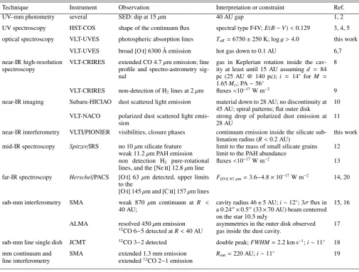
HD 135344B has been observed with a diversity of instruments and techniques from UV to mm wavelengths. In Table1, we present a concise summary of relevant previous observational constraints on HD 135344B. The most important observational constraints for this study are:
• the SED has a dip in the 10−50 µm region (Brown et al.
2007);
• the 10µm silicate feature is absent (Geers et al. 2006); • the inner radius of the sub-mm cavity is 46±5 AU (Brown
et al. 2009;Andrews et al. 2011);
• the 3σcontinuum flux upper limit at 870µm is 10.5 mJy for
a 0.2400 ×0.500 beam centered on the star (Andrews et al.
2011);
• CO ro-vibrational emission extends at least to 15 AU inside
the sub-mm dust cavity (25 AU ford=140 pc) (Pontoppidan
et al. 2008)1;
1 Pontoppidan et al.(2008) suggests a minimum extension of 15 AU
assuming a distance of 84 pc. The distance currently used to interpret HD 135344B data (Brown et al. 2009;Andrews et al. 2011) is 140 pc
(van Boekel et al. 2005). IfRout constraint is scaled to the 140 pc, that
Table 1.Summary of most relevant previous observations and disk constraints.
Technique Instrument Observation Interpretation or constraint Ref.
UV–mm photometry several SED: dip at 15µm 40 AU gap 1, 2
UV spectroscopy HST-COS shape of the continuum flux spectral type F4V;E(B−V)<0.129 3, 4, 5
optical spectroscopy VLT-UVES photospheric absorption lines Teff =6750±250 K; logg >4.0 this work
VLT-UVES broad [O
] 6300 Å emission hot gas down to 0.1 AU 6,7near-IR high-resolution
spectroscopy VLT-CRIRES extended CO 4.7profile and spectro-astrometry sig-µm emission; line nal
gas in Keplerian rotation inside the cav-ity at least until 15 AU assuming d = 84 pc (25 AU @ 140 pc); i = 14◦ for
M = 1.65M; PA∼56◦
8
VLT-CRIRES non-detection of H2lines at 2µm fluxes<10−17W m−2 9
near-IR imaging Subaru-HICIAO dust scattered light emission material down to 28 AU; no discontinuity at 45 AU; spiral patterns; flat outer disk 10 VLT-NACO polarized dust scattered light
emis-sion strong drop of polarized dust emission at28 AU 11 near-IR interferometry VLTI/PIONIER visibilities, closure phases continuum emission inside the silicate
sub-limation radius (R<0.2 AU) this work mid-IR spectroscopy Spitzer/IRS no 10µm silicate feature limit to the mass of small silicate grains 12
weak 11.2µm PAH emission limit to the PAH abundance non detection H2 pure-rotational
lines, and the [Ne
] 12.8µm linefluxes<10−17W m−2 13
far-IR spectroscopy Herschel/PACS [O
] 63µm detected, upper limitsto the F[O] 63µm=3.6−4.8×10
−17W m−2 14, 20
[O
] 145µm and [C
] 157µm linessub-mm interferometry SMA weak 870 µm continuum at R <
40 AU; cavity radius 46
±5 AU;i∼12◦; 3σflux in
a 0.2400×0.500(33×70 AU) beam centerred
on the star 10.5 mJy
15, 16
ALMA resolved 450µm emission asymmetries in the outer disk observed 17
12CO 6−5 detected atR<40 AU gas inside the dust cavity.
sub-mm line single dish JCMT 12CO 3−2 detected double peak;FWHM=2.2 km s−1;
i∼11◦ 18
mm continuum and SMA extended 1.3 mm emission Rout=220 AU;i∼11◦ 19
line interferometry extended12CO 2−1 emission
References.[1] see TableA.1, [2]Brown et al.(2007), [3]Grady et al.(2009), [4]France et al.(2012), [5]Schindhelm et al.(2012), [6]van der Plas
et al.(2008), [7]Fedele et al.(2008), [8]Pontoppidan et al.(2008), [9]Carmona et al.(2011), [10]Muto et al.(2012), [11]Garufi et al.(2013),
[12]Geers et al.(2006), [13]Lahuis et al.(2007), [14]Meeus et al.(2012), [15]Brown et al.(2009), [16]Andrews et al.(2011), [17]Pérez et al.
(2014), [18]Dent et al.(2005), [19]Lyo et al.(2011), [20]Fedele et al.(2013).
• near-IR dust scattering images reveal small dust inside the
sub-mm cavity down to 28 AU with a smooth surface bright-ness and no discontinuity at 45 AU (Muto et al. 2012;Garufi et al. 2013).
3. Modeling
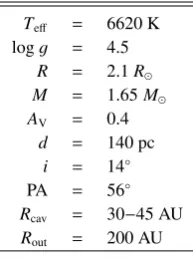
3.1. Stellar parameters
We provide a detailed discussion of the derivation of the stel-lar parameters in the Appendix A.2. For our models we used a star with Teff = 6620 K (F4V), a stellar radius of 2.1R,
a mass of 1.65 M, and Av = 0.4. Owing to uncertainties in
the photometry, the spectral type and, especially, the distance (±20 pc) the stellar radius can vary±0.3R, and the stellar mass
does so±0.1M. The stellar UV spectrum2 was parametrized
with a fractional UV excess fUV=LUV/L?equal to 0.001 (LUV
2 FUSE and HST-COS spectra were obtained from DIANA
pro-toplanetary disk observations and modeling database (http://www. diana-project.com/). Details on the data reduction procedures will be given in Dionatos et al. (in prep.).
is defined as the luminosity between 91.2 and 250 nm) and
Fν∝νγwithγ=−2.15. This parametrized stellar UV spectrum
is included in the P
D
M
gas heating calculation in additionto the interstellar UV field.
3.2. Disk inclination and position angle
Several data sets give different inclinations for HD 135344B: CO 4.7µm emission suggestsi = 14◦±4◦ (Pontoppidan et al.
2008, forM =1.65M); the COJ =3−2 line at 870µm
indi-catesi=11◦±2◦(Dent et al. 2005); sub-mm continuum
imag-ing points towardi=12◦(Andrews et al. 2011) and 21◦(Brown
et al. 2009); mm interferometry suggests i = 11◦ (Lyo et al.
2011); near-IR imaging sets an upper limit ofi = 20◦ Grady
et al.(2009); mid-IR imaging suggests i = 46◦±5◦ (Doucet
et al. 2006) and 45◦±5◦(Mariñas et al. 2011). For our
analy-sis of the SED and line profiles, we usedi =14◦. We used this
because it is consistent with the inclination derived from the ob-servations of CO gas in the outer disk3.
Several estimations exist for the disk’s position angle (PA). Pontoppidan et al. (2008) suggest a PA = 56◦ ±2◦ based on
spectro-astrometry of the CO 4.7 µm emission; Grady et al. (2009) suggest a PA=55◦±5◦based on near-IR scattered light
imaging; Andrews et al. (2011),Brown et al. (2009), andLyo et al. (2011) based on (sub-)mm interferometry continuum ob-servations suggest a PA=64◦, 55◦, and 64◦respectively. As we
aim to compare our model with the CO 4.7 µm lines we em-ployed a PA of 56◦.
3.3. Description of the general modeling procedure
We aimed to
1. simultaneously fitthe SED, the line profile of the COν =
1−0 P(10) line at 4.7545µm, and the near-IR PIONIER
vis-ibilities and closure phases;
2. reproduce within a factor of a fewthe detected line fluxes of
CO P(10), [O
] at 63 µm,12CO J = 3−2 at 870µm, and 12COJ=2−1 at 1.27 mm;3. obtain line fluxes below the upper limitsfor [O
] at 145µm,[C
] at 157 µm, H2 1−0 S(1) at 2.12µm, H2 0−0 S(1) at17µm, and CO and H2O infrared lines covered byHerschel
(see TablesA.2andA.3);
4. obtaina 870µm flux inside a beam of 400×0.500(33×70 AU)
centered on the star lower than 10.5 mJy.
To be consistent with the sub-mm continuum constraints, the in-ner radius of the outer disk’s large and small grains was set to 45 AU. Later in the modeling process, the inner radius of the outer disk’s small grains was allowed to extend down to 30 AU to be consistent with the near-IR scattered-light constraints.
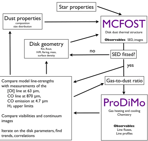
In Fig.1, we provide an schematic overview of the modeling procedure. The modeling starts by assuming a dust composition, a dust size distribution, a dust mass, and a gas-to-dust ratio, for the inner and the outer disk using a parametric disk (see details in next section). Then the Monte Carlo dust radiative transfer code MCFOST (Pinte et al. 2006,2009) is used to calculate the dust’s thermal and density structure,Tdust(r,z),ndust(r,z), and the
mean radiation fieldJν(r,z). MCFOST is employed to compute
a synthetic SED, and continuum images in the H band and at 870µm for comparison with VLTI/PIONIER and SMA contin-uum observations.
The MCFOST disk structure and radiation field is then used as input for the thermochemical radiative transfer code P
D
M
(Woitke et al. 2009). P
D
M
calculates the diskchemistry, the gas and dust heating and cooling, and the energy level populations of molecules and atoms. P
D
M
computesthe synthetic line fluxes and channel maps for gas emission lines from the optical to the mm using escape probability.
Details of the coupling between the codes MCFOST and P
D
M
and brief summaries of technical details of bothcodes are provided inWoitke et al.(2010),Pinte et al.(2010),
3 Recent near-IR imaging (Muto et al. 2012;Garufi et al. 2013) and
sub-mm interferometry (Brown et al. 2009;Andrews et al. 2011;Pérez
et al. 2014) have revealed that the disk of HD 135344B has spiral arms
and asymmetries in the dust emission. One possible reason for the dis-crepancy between the inclination derived from mid-IR imaging data (i.e., dust emission) and the inclination derived from near-IR and sub-mm CO gas observations is that disk asysub-mmetries could be present in the mid-IR dust emission, hence a different estimate of the inclination and PA.
Dust properties
composition size distribution
Disk geometry
Rin, Rout, H/R, flaring, mass,
surface density
Star properties
MCFOST
Disk dust thermal structureObservables: SED, images
ProDiMo
Gas heating and coolingChemistry
Observables: Line fluxes, Line profiles
Compare model line-strengths with measurements of the [OI] line at 63 μm, CO line at 870 μm, CO emission at 4.7 μm H2 upper limits
Compare visibilities and continuum images
Iterate on the disk parameters, find trends, correlations
SED fitted?
yes no
[image:4.595.309.555.73.307.2]Gas-to-dust ratio
Fig. 1.Schematic view of the general modeling procedure.
andKamp et al.(2011). Details of the implementation of CO ro-vibrational emission within P
D
M
are given inThi et al.(2013).
The modeling was performed without computing the hy-drostatic equilibrium. The disk gas and dust density distribu-tion (thus the gas-to-dust ratio) was set as input. We chose this approach to explore a large fraction of the parameter space. Computing the hydrostatic equilibrium would have resulted in a running time an order of magnitude longer and would have pre-vented us from performing a large exploration of the parameter space. We have verified that our last model, Model 5, is consis-tent with hydrostatic equilibrium; i.e., the scale height we used as input is consistent withhhydro =
q
kTgas (z=0)r3/GMµ.
We started our exploration with simple models, and com-plexity in the model was only added when we were not able to fit some of the observations. The model was refined sequentially following this protocol:
1. fit the SED,
2. fit the CO P(10) ro-vibrational line-profile,
3. check consistency with SMA 870µm continuum upper lim-its inside the cavity,
4. describe near-IR visibilities,
5. produce an [O
] 63µm line flux consistent with theHerschelobservations,
6. refine the model to account for the latest near-IR polarization images (Garufi et al. 2013).
For each family of models, a large portion of the parameter space was explored by a combination of hand exploration, grid mod-eling, and simplex optimization algorithms. In total we tested
∼60 000 MCFOST models and∼4000 P
D
M
models.3.4. Disk structure and MCFOST parameters
Table 2.HD 135344B stellar and geometrical parameters used for the
modeling.
Teff = 6620 K
logg = 4.5 R = 2.1R
M = 1.65M
AV = 0.4
d = 140 pc i = 14◦
PA = 56◦
Rcav = 30−45 AU
Rout = 200 AU
a scale heighth0 at a reference radiusr0, flaring exponent (β),
and surface density exponent (q). Each zone has a Gaussian
vertical density profileρ(r,z)=ρ0(r) exp (−z2/2h(r)2), a
power-law surface densityΣ(r) = Σ0(r/r0)q, and a scale heighth(r)= h0(r/r0)β, whereβis the flaring exponent,rthe radial coordinate
in the equatorial plane, andh0the scale height at the reference
radiusr0.
For each zone, the dust composition, the dust size distribu-tion, the dust mass, and the gas-to-dust ratio are defined inde-pendently. One zone can include several dust components, such as silicate grains, carbonaceous grains, or PAHs. Zones can have Gaussian inner edges of size five times the parameter “edge”. In our models, for each zone, the gas-to-dust ratio is constant in the vertical direction.
Dust grains are defined as homogeneous and spherical par-ticles with sizes distributed according to the power law dn(a)∝ apda, witha
min andamax the minimum and maximum sizes of
the grains. We used the standard valuep=−3.5. Extinction and
scattering opacities, scattering phase functions, and Mueller ma-trices are calculated using the Mie theory. We employed the as-tronomical silicates opacities ofDraine & Lee(1984), the neutral PAH opacities computed by B. T. Draine (compiled from Laor & Draine 1993;Draine & Lee 1984;Li & Draine 2001), and the amorphous carbonaceous dust optical constants derived byLi & Greenberg(1997).
In summary, the free parameters of a model are the number of zones used to describe a disk, and for each zoneRin,Rout,p,β, q,h/r,edge,Mdust, gas-to-dust ratio, and dust composition, and
for each dust speciesamin, andamax.
Sub-mm continuum images were convolved with a 0.2400×
0.500beam for comparison with SMA observations.
3.5. ProDiMo parameters
We used the cosmic ray ionization rate of H2of 5×10⁻¹⁷s−1. The
incident vertical UV was set to the interstellar medium value. Non-thermal broadening was set to 0.15 km s−1. We used the
UMIST chemical network (9 elements, 71 species connected through 950 reactions neutral-neutral, ion-molecule, photoreac-tions, cosmic ray reacphotoreac-tions, and absorption & desorption of CO, CO2, H2O, NH3, CH4, seeWoitke et al. 2009). UV fluorescence
is included for [O
] and [C
] but not for CO. UV COfluores-cence has been included as a test later in the paper. A list of the species we used is provided inWoitke et al.(2009).
Table 3.P
D
M
general parameters.ISM UV field (χ, Draine) = 1.0 Non-thermal broadening = 0.15 km s−1
fractional UV excess = 0.001 UV power-law index = –2.15 Cosmic ray ionization rate of H2ζ = 5×10⁻¹⁷s−1
3.6. CO 4.7µm data and slit effects
For our analysis, we downloaded the 1D CO 4.7µm reduced spectrum used inPontoppidan et al.(2008)4. We flux-calibrated
the spectrum using theSpitzerflux at 4.7µm (see Appendix A
for the photometry) and measured the CO line fluxes by fitting a Gaussian to their line profile. The CO P(1) to P(11) line profiles are available within the CRIRES spectrum. After subtracting the continuum and normalization by the peak flux, the lines have the same line profile within the errors (see Fig.A.3). We selected the CO P(10) line for detailed modeling because the line profile is complete, is weakly affected by nearby strong telluric absorp-tion lines, and has good signal-to-noise ratio (S/N). The line CO P(10) line flux is 1.5×10⁻¹⁷ W m−2 with an error on the order
of 20% owing to slit losses and systematics.
To compare the P
D
M
predictions with the observedCRIRES CO 4.7 µm spectra, the effects of the slit width and orientation, the observing conditions, and spectral resolution needed to be taken into account.
P
D
M
generates channel maps data cubes; i.e., for eachvelocity bin, a 2D image of CO emission is generated (see details inHein Bertelsen et al. 2014). The pixel size of the CRIRES detector in the spatial direction is 0.08600, at a distance of 140 pc
that corresponds to a pixel size of ∼12 AU. We generated the
P
D
M
data cubes with a pixel size of 2 AU.The P
D
M
data cubes were first convolved in the spatialdirection with a Gaussian PSF ofFWHM=180 mas. Then they
were convolved with a Gaussian ofFWHM=3.3 km s−1in the
wavelength direction to simulateR=90 000 of the observations.
A mask of 0.200(28 AU) with the correct PA was applied in each
channel to mimic the slit. The fluxes were added in the direction perpendicular to the slit to generate a 2D spectrum.
In the 2D spectrum the centroid of the photocenter at line velocity (υ) was calculated using (Pontoppidan et al. 2008)
X(υ)=K
P
i(xi(υ)−x0)Fi(υ) P
iFi(υ)
(pixels) (1)
wherexi−x0is the center of pixelirelative the continuum
cen-troid position,Fi(υ) is the flux on the pixeli, andKis a
correc-tion factor to take into account that not all of the source flux is enclosed in the aperture (Pontoppidan et al. 2008). We employed
K = 1.3 used byPontoppidan et al.(2008) in their analysis of
the spectro-astrometry signal of HD 135344B to be able to com-pare our models to their measurements. A 1D spectrum is further obtained by summing the pixels in the spatial direction. To com-pare the observed and synthetic line profiles, the spectra were normalized by dividing them by the median of the continuum, then after continuum subtraction, the profile was renormalized
4 Available on the webpage of the CRIRES large program “The
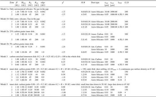
Table 4.Summary of model parameters.
Zone βa M
dust Rin Rout edge qb H/R Dust type a
min amax fPAH G/D
[M] [AU] [AU] [AU] [AU] [µm] [µm]
Model 1a Only astronomical silicates. No gas in the gap
1 1.10 7.0E-10 0.16 0.21 0.002 –1.5 0.016/0.10 Astro-Silicates 10.00 1000.00 100
2 1.00 1.1E-04 45 200 1.0 –2.5 4.5/45 Astro-Silicates 0.05 1000.00 6.5E-3 100
Model 1b Only astro. silicates. Gas in the gap
1 1.10 7.0E-10 0.16 0.21 0.002 –1.5 0.016/0.10 Astro-Silicates 10.00 2000.00 100
2 1.10 1.0E-08 0.21 40 0.0 –1.0 0.015/0.10 Astro-Silicates 10.00 2000.00 100
3 1.00 1.1E-04 45 200 1.0 –2.5 4.5/45 Astro-Silicates 0.05 1000.00 6.5E-3 100
Model 2a 25% carbon grains inner disk
1 1.25 1.8E-10 0.18 20 0.001 –1.5 0.012/0.10 Amor. Carbon 0.01 10 100
Astro-Silicates 0.01 1000
2 1.00 1.0E-04 45 200 1.0 –2.5 5.5/45 Astro-Silicates 0.05 1000 6.5E-3 100
Model 2b 5% carbon grains inner disk
1 1.00 3.0E-10 0.18 3 0.001 –2.0 0.010/0.10 Am. Carbon 0.01 10 100
Astro-Silicates 10 1000 100
2 1.00 1.1E-04 45 200 1.0 –2.5 6.0/45 Astro-Silicates 0.05 1000 6.5E-3 100
Model 3 carbon-enriched innermost disk (0.2<R<0.25 AU);G/D=100 in the whole disk
1 1.00 6.0E-12 0.21 30 0.002 –5.0 0.010/0.10 Am. Carbon 0.01 10 100
2 1.00 1.0E-06 0.21 30 0.002 0.25 0.015/0.10 Astro-Silicates 100 2000 100
3 0.60 1.0E-04 45 200 1.0 –2.0 6.3/45 Astro-Silicates 0.05 1000 6.5E-3 100
Model 4 inner disk: carbon grains 0.08<R<0.2 AU; silicates 0.2<R<45 AU; (G/D)inner=150; outer disk: dust settling, (G/D)outer=2; continuous gas surface density at 45 AU
1 1.10 2.5E-12 0.085 0.20 0.002 0.0 0.012/0.10 Am. Carbon 0.01 10 150
2 1.12 3.5E-07 0.20 44 0.0 0.30 1.2/10 Astro-Silicates 0.10 1000 150
3 1.0 0.4E-04 45 200 0.0 –1.0 1.2/10 Astro-Silicates 0.01 10 0.18 2
4 1.0 1.6E-04 45 200 0.0 –1.0 0.5/10 Astro-Silicates 0.01 1000 0.18 2
Model 5 inner disk: carbon grains 0.08<R<0.2 AU; silicates 0.2<R<30 AU; outer disk: small dust dust down to 30 AU, large dust down to 45 AU
1 1.10 2.5E-12 0.085 0.20 0.002 0.00 0.012/0.10 Am. Carbon 0.01 10 100
2 1.12 1.0E-07 0.20 30.00 0.0 0.20 1.1/10 Astro-Silicates 0.10 1000 150
3 1.00 0.5E-04 30.00 200.00 0.0 –1.00 1.1/10 Astro-Silicates 0.01 10 0.09 4
4 1.00 1.5E-04 45.00 200.00 1.0 –1.00 0.7/10 Astro-Silicates 0.01 1000 0.09 4
Notes.(a)βis the flaring exponent;(b)qis the surface density exponent.
by dividing it by its maximum flux. In this way the continuum is always at 0 and the line peak is always at 1. The integrated line fluxes of the model (taking the slit effects into account) and the line profiles were compared to the observations separately.
4. Modeling results
Before presenting the family of models 5, the model that best describes the observations, we briefly describe the sequence of families of models we tested to illustrate the reasoning that lead us to the final model. A family of models is defined primarily by its dust properties (i.e., composition and location). We have extensively explored the parameter space in each family of mod-els. However, we limit the discussion to the parameter space on the family of models 5. In Table 4we present the details of a representative example of each family of models. The different families of models show us the close relation that exists between the properties assumed for the dust (size distribution, composi-tion, and mass) at the beginning of the modeling procedure and the gas lines obtained.
4.1. Family of models 1: a disk only composed of astronomical silicate grains
As starting point we assumed the simplest model, which has an inner and outer disk composed of 100% astronomical silicates
and a gas-to-dust ratio of 100 in the whole disk. The solutions all converged to the same disk structure, namely a narrow ring of dust at 0.16 to 0.21 AU with a dust mass of a few 10−10 M
with grains larger than 10µm (to reproduce the lack of 10µm silicate feature), followed by a large gap of 45 AU and an outer disk from 45 to 200 AU with dust mass of 10−4 M. By
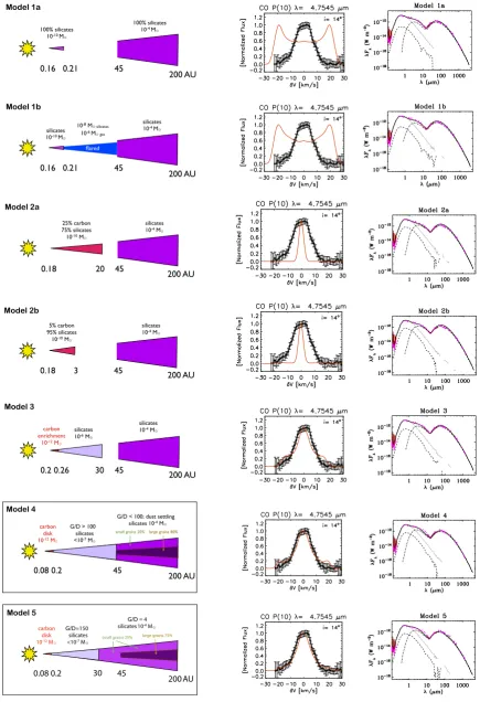
changing the disk’s geometrical parameters, we found a disk able to reproduce most of the observed gas line fluxes (see Model 1a in Tables4and5). However, because in this model the warm gas is located in the narrow innermost region, the CO ro-vibrational emission produced has a broad double-peaked profile withFWHM ∼50 km s−1 that is inconsistent with the observed FWHM∼15 km s−1(see Model 1a in Fig.3).
With the aim of producing CO ro-vibrational emission ex-tending tens of AU and a narrower line profile, in Model 1b, we introduced gas (and dust) between 0.21 and 45 AU. We found that although up to 10−8 M of dust and 10−6 M of gas can
be introduced inside the cavity and still fit the SED, the CO ro-vibrational line always displayed a broad double peaked profile with a FHWM of ∼50 km s−1. We tested many flat and flared
Table 5.Observed and modeled line fluxes.
[O
] [O
] [C
] 12COJ3−2 12COJ2−1 ν=1−0 P(10)a H21−0S(1) H20−0S(1)
63µm 145µm 157µm 866µm 1.3 mm 4.7545µm 2.12µm 17.03µm Observed 3.6−4.8E-17 <4.6E-18 <6.4E-18 1.2E-19 8.0E-20 1.5E-17 <1.6E-17 <1.0E-17
Model 1a 5.4E-17 4.4E-18 3.7E-18 2.3E-19 7.4E-20 1.6E-17 74% 8.2E-20 1.9E-19 Model 1b 7.2E-17 5.5E-18 4.7E-18 2.5E-19 7.8E-20 1.7E-17 74% 1.8E-19 4.4E-19 Model 2a 2.7E-16 1.8E-17 8.7E-18 2.6E-19 8.0E-20 1.5E-17 21% 5.4E-18 9.4E-18 Model 2b 3.4E-16 2.8E-17 1.2E-17 3.3E-19 1.0E-19 7.4E-17 26% 8.7E-18 1.2E-17 Model 3 2.6E-16 2.0E-17 1.2E-17 2.8E-19 8.5E-20 1.2E-17 66% 1.5E-18 4.6E-18 Model 4 4.0E-17 2.4E-18 2.2E-18 1.6E-19 5.0E-20 3.7E-18 72% 5.4E-19 2.6E-19 Model 5 3.2E-17 1.5E-18 1.7E-18 1.5E-19 4.7E-20 2.5E-18 72% 6.0E-19 1.8E-19
Notes.(a)The percentage after the CO P(10) line-flux corresponds to the fraction of line flux retrieved inside the slit.
Fig. 2.Expected PAH spectrum (black) andSpitzerIRS spectrum (in
red) for different dust mass fractions of neutral PAHs in the outer disk. In the rest of the paper, we used a 0.01% PAH fraction. NC=number of carbon atoms. Magenta points are photometry points (see Appendix A).
4.1.1. PAH content
PAHs are an important ingredient for calculating the gas heating. To constrain the PAHs, we employed theSpitzer/IRS spectrum5.
PAHs are implemented as a second dust component in MCFOST. Their properties (abundance and size) are passed to P
D
M
inorder to compute the gas heating due to the photoelectric effect. Initially, we found that the observed 11.2 µm PAH feature could be reproduced with neutral PAHs with 21 carbon atoms (NC=21) and 0.01% of the dust in the outer disk in the form
5 For our analysis, we downloaded theSpitzer/IRS observations (AOR
3580672, PI: Houck) from the Spitzerarchive and reduced the data again. The short-low data were reduced using the FEPS pipeline (S18.18.0, see Bouwman et al. 2008). The short-high and the long-high data were reduced with the c2d pipeline (S18.18.0, Lahuis et al. 2006). For the high-resolution modules, we used the PSF extraction method, which includes correction for pointing uncertainties. The mid-IR spec-trum of HD 135334B is characterized by the absence of the silicate feature at 10µm, weak PAH emission at 11.2µm, and a lack of other PAH emission features (Geers et al. 2006;Maaskant et al. 2013).
of PAHs. However, such PAHs generated too much gas heating that translated into [O
] 63µm line fluxes that are three to tentimes stronger than the observations for almost all the models reproducing the SED. To have an [O
] 63µm emissioncompat-ible within a factor 3 of the observations, we increased the PAH size to NC=100 and used a 0.01% fraction in mass of the dust in the form of PAHs (fPAH=6.0×10⁻³for a gas-to-dust ratio of
100, see Fig.2).
4.2. Family of models 2: an inner disk composed of a uniform mixture of amorphous carbon and astronomical silicates
To modify the continuum optical depth of the inner disk and to make it possible for the gas at larger radii (R 1 AU) to
con-tribute to the CO 4.7µm emission, we introduced amorphous carbonaceous grains in the dust mixture in the family of mod-els 2. Amorphous carbonaceous grains are commonly employed to fit SEDs of T Tauri and Herbig Ae/Be stars. We assumed first a carbonaceous/silicate grains ratio constant with radius. The frac-tion of carbon grains in the dust mixture sets the extension of the inner disk that fits the near-IR SED. The greater the fraction of carbon grains, the larger the inner disk that reproduces the near-IR continuum. With a 25% fraction of carbonaceous grains, an inner disk extending from 0.18 to 20 AU fits the near-IR SED (see Model 2a in Table4). With a 5% carbon fraction, an inner disk extending from 0.18 to 3 AU is required (Model 2b).
The introduction of amorphous carbon grains reduced the to-tal dust mass required to fit the near-IR SED by a factor of a few, allowed for a dust size distribution with smaller grains in the inner disk (and fit the lack of 10µm silicate feature), and dras-tically changed the inner disk’s optical continuum depth. These changes resulted in an optically thin inner disk at 4.7µm, thus a CO ro-vibrational emission entirely dominated by emission from the inner rim of the outer disk, and a very narrow single peaked CO ro-vibrational line profile with a width of a few km s−1,
in-consistent with the observations (see Fig.3).
4.3. Family of models 3: an inner disk with a
radial-dependent mixture of carbon and silicates
The results of the families of models 1 and 2 suggested that the solution was an intermediate inner disk structure between a nar-row disk of 100% silicates and an extended inner disk with a large amount of carbonaceous grains. In the family of models 3, we allowed for a radial-dependent carbonaceous/silicate grains ratio.
[image:7.595.81.250.237.494.2]200 AU
0.16 0.21 45
Model 1a
flared
100% silicates 10-10 M⊙
100% silicates 10-4 M⊙
200 AU
0.16 0.21 45
Model 1b
flared 10-8 M⊙ silicates
10-6 M⊙ gas silicates
10-10 M⊙
silicates 10-4 M⊙
200 AU
0.18 20 45
Model 2a
25% carbon 75% silicates
10-10M ⊙
silicates 10-4M⊙
200 AU
0.18 3 45
Model 2b
5% carbon 95% silicates
10-10M ⊙
silicates 10-4M⊙
200 AU 0.2 0.26 30 45
Model 3
carbon enrichment
10-12 M ⊙
silicates 10-6M⊙
silicates 10-4M⊙
0.08 0.2 45
Model 4
G/D < 100; dust settling silicates 10-4 M G/D > 100
silicates <10-7 M carbon
disk 10-12 M
200 AU small grains 20% large grains 80%
0.08 0.2 30
Model 5
G/D = 4 silicates 10-4 M
G/D=150
silicates <10-7 M
carbon disk
10-12 M small grains 25%
200 AU 45
[image:8.595.81.517.77.714.2]large grains 75%
Fig. 3. Cartoon displaying the disk structure of the family of models tested, together with the CO P(10) line profile and SED predicted. The
CO P(10) line profile includes the effects of the slit, and it is displayed for PA of the slit of 180◦. A representative example of each family of
10-19 10-18 10-17 10-16
12CO P(10) [W m-2]
10-17 10-16 10-15
!
"
##∃%#&
m [W m
-2]
1
1: Model 3 G/D=100 O/C= 2.37
2
2: G/D=20
3
3: G/D=10
4
4: G/D=10 COpump 5
5: H2O ro-vib. cooling
6
6: low Z
7
7: O/C= 1.0 8
8: O/C= 0.25
9
9: Tgas=Tdust
10
[image:9.595.314.551.72.573.2]10: no PAH
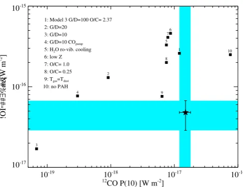
Fig. 4. Effect of changing different P
D
M
assumptions in the[O
] 63µm and CO P(10) line fluxes in one representative exampleof the family of models 3. The star indicates the observed line fluxes. The cyan intervals represent the 20% error on the CO P(10) line flux and 40% error in the [O
] 63µm line flux. In the legend the symbolsmean: G/D: gas-to-dust ratio; COpump: CO ro-vibrational emission
cal-culated including UV fluorescent excitation; H2Ocooling: gas temperature
calculated including ro-vibrational water cooling (pure rotational H2O
cooling is always taken into account); low Z: low disk metallicity; O/C: oxygen over carbon abundance ratio;Tgas =Tdust: maximum possible
cooling; no PAH: gas heating calculated without the effect of PAHs.
amorphous carbon grains at small radii (0.2 < R < 0.26 AU)
is able to reproduce the near-IR SED, while at the same time it makes it possible for the CO located at several AU to contribute significantly to the CO ro-vibrational line flux, thus reproducing the observed CO P(10) line profile (see Fig.3).
Assuming a gas-to-dust ratio of 100 for the whole disk and a carbon-enriched inner disk, we tested a large number of models (∼50 000 MCFOST,∼1000 P
D
M
) by varying the geometry(i.e., H/R, flaring, surface density exponent) and dust mass for the inner and outer disk. We found that the CO ro-vibrational line profile is reproduced by an inner disk extending tens of AU in which the surface density is flat or increases as a function of the radius (i.e., a power-law surface density with a positive exponent). Solutions with flared and anti-flared outer disks were found.
Several Models 3 reproduced the CO P(10) flux and line pro-file, the H2infrared lines upper-limits, and the CO sub-mm and
mm line fluxes (see one example in Tables4and5). However, in all Models 3 calculated (covering a wide range of geometries), the emission of [OI] 63 and 145µm, and the [C
] line at 157µmwere overpredicted by factors over five. We tested several op-tions available within P
D
M
(see Fig.4), such as globalgas-to-dust ratios lower than 100, H2O ro-vibrational cooling (pure
H2O rotational cooling is calculated by default), lower
metal-licity, no PAHs, extremely low O/C abundances, but in most of the cases the [O
] 63 and 145 µm lines were still too strong.We found that the only effective ways to significantly decrease the [O
] 63 and 145µm line fluxes were to assumeTgas=Tdustor tosignificantlydecrease the gas-to-dust ratio. The first is an
extreme case of gas cooling that is unrealistic, as we know that
Tgas>Tdustin the disk’s surface layer (e.g.,Kamp & Dullemond
2004). The second had the limitation that when theglobal
gas-to-dust ratio was low enough to describe the [O
] 63µm line,the CO ro-vibrational line was two orders of magnitude weaker.
Model 3
20 40 60 80
0.0 0.5 1.0
40 60 80
−50 0
B/λ
V2
Bmax/λ
CP
Model 4
20 40 60 80
0.0 0.5 1.0
40 60 80
−10
−5
0 5 10
B/λ
V2
Bmax/λ
CP
Fig. 5.Upper panel: squared visibilities(in red)of Model 3
overplot-ted onto the observed 1.6µm VLTI/PIONIER visibilities (in black). An inner disk starting at 0.2 AU is not consistent with observations. VLTI/PIONIER data clearly shows that there is material at smaller radii (i.e., inside the silicate sublimation radius).Central panel: squared visibilities (in red) predicted by Model 4 (Rin = 0.08 AU).Lower panel: closure phases (CP) predicted by Model 4 (red) and measured by VLTI/PIONIER (black).
This last result indicated that the gas-to-dust ratio should be dif-ferent for the inner and outer disk.
[image:9.595.42.287.73.262.2]compatible with the interferometry data. The near-IR continuum in Model 3 is produced too far out.
4.4. Family of models 4: Carbon grains inside the silicate sublimation radius, different gas-to-dust ratios for the inner and outer disk, and dust settling in the outer disk
4.4.1. The location of the carbonaceous dust
In the family of models 3, the carbonaceous grains were lo-cated at R > 0.2 AU to be consistent with the assumption
that the temperature in the inner rim should not be higher than the silicate grains sublimation temperature (T ∼ 1500 K, for nH >∼ 1016 cm−3, e.g.,Helling et al. 2001). However,
carbona-ceous grains can survive temperatures higher than 1500 K and up to 2000 K (see for example,Kobayashi et al. 2011). Therefore, one interesting possibility for physically justifying the inner-disk carbon enrichment is that the carbonaceous grains are located inside 0.2 AU, the region where silicate grains sublimate. The survival of carbonaceous grains in this region is discussed in Sect.6.2.
Therefore for the family of models 4, we located the car-bonaceous grain component at 0.08 < R < 0.2 AU,Rin equal
the corotation radius, and Rout equals the silicates sublimation
radius. The astronomical silicate-grain component of the inner disk was set to start at 0.2 AU. With this inner disk configura-tion we obtained an excellent match to SED and the PIONIER visibilities and closure phases (see Fig. 5). In our models the temperature at the innermost radius is∼2000 K.
4.4.2. Decreasing the [OI] 63µm emission
One limitation of the family of models 3 was that it produced [O
] 63µm line fluxes that are too strong. The [O
] 63µm lineis emitted partly by gas inside the cavity between 10 and 45 AU, but principally by gas in the outer disk between 45 and 60 AU. Since the surface density and gas mass in the inner disk are set by the CO ro-vibrational line, to lower the [O
] line fluxes, threemodifications to the family of models 3 were introduced in the family of models 4:
1. the gas-to-dust ratio in the outer disk was allowed to be lower than 100,
2. the surface density of the outer disk needed to be shallower, (We obtained good solutions withq = −1.0, similar to the
surface density power law exponent found byAndrews et al. (2011) from SMA sub-mm continuum observations). 3. the scale height of the outer disk needed to be lower
than 10%.
These changes in the outer disk geometry led to a bad fit of SED at λ > 15 µm. To resolve this, a fourth modification was introduced in the outer disk by splitting it into two super-posed disks. A first disk with lower H/R (5%), with 80% of the gas and dust mass, and with a dust population of large grains (0.01 < a < 1000 µm); and a second disk with higher H/R
(0.8−0.13), with the 20% remaining gas and dust mass, and with
a dust population of smaller grains (0.01 < a < 10µm). This
modification aims to keep most of the gas mass of the outer disk at low H/R (to fit the [O
] 63µm line), while allowing somesmall dust particles to be present in an extended outer disk at-mosphere at higher H/R to fit the SED atλ >15µm. This two-layered outer disk echoes the expected effect by dust coagulation and sedimentation (i.e., large grains closer to the midplane).
Finally, for the inner disk, to address the fact that scattered light imaging (Muto et al. 2012;Garufi et al. 2013) revealed ma-terial inside the cavity down to 28 AU, we set, as a first approx-imation, the inner disk to have an outer radius of 45 AU, such that the whole cavity is replenished with gas, and we allowed the gas-to-dust ratio to be over 100 in the inner disk to be able to have sufficiently high CO 4.7µm emission.
With this ensemble of modifications, we found a family of disk models able to simultaneously describe the SED, the CO P(10) line profile, the line fluxes of [O
] 63µm (within afactor 2), CO P(10) (within a factor 4),12CO 3−2, 12CO 2−1,
and the upper limits of [O
] at 145 µm, [C
] at 157 µm,and the H2 lines in the near and mid-IR. The properties of a
representative model of the family of models 4 is described in Table4, and the line fluxes predicted are presented in Table5.
The family of models 4 confirmed the result that to describe the CO P(10) line profile, the gas in the inner disk should be distributed with a surface density increasing as a function of the radius, and indicated that to describe the [O
] 63 µm lineflux, the gas-to-dust ratio in the outer disk should be much lower than 100. The best match to the [O
] 63µm line flux wasob-tained by a gas-to-ratio below 10; nevertheless, gas-to-dust ra-tios up to 40 provided [O
] 63µm fluxes within a factor 2 of theobservations.
4.5. Family of models 5: introducing recent constraints from polarized and mid-IR imaging
In a recent workGarufi et al.(2013) has shown that polarized scattered light in HD 135344B drops significantly at a radius of 28 AU. A lack of polarized emission can be the signature of either a lack of material or a change in the illumination of mate-rial inside the cavity. Similarly,Maaskant et al.(2013) propose a cavity of size 30 AU based on modeling the SED and mid-IR imaging. The detection of scattered light down to 28 AU, inside the sub-mm dust cavity of 45 AU, indicates a different spatial location for the small and large dust grains in the outer disk.
To account for the recent results from Garufi et al.(2013), we slightly modified the disk structure of the family of mod-els 4. First, we shortened the outer radius of the inner disk to 30 AU and decreased its dust mass to keep it consistent with the SMA 870µm upper limit. Second, we extended the small parti-cle component of the outer disk down to 30 AU. The large grain component of the outer disk was kept at 45 AU to account for the sub-mm 870µm imaging constraints.
With these modifications, we obtained a disk structure com-patible with the Garufi disk structure, while keeping the fit to the SED and the gas lines. Our model has gas and (some) dust inside 30 AU to account for the extended CO ro-vibrational line ob-served. However, the amount of dust atR<30 AU (<10−7M) is
much less than the amount of dust in the outer disk (2×10⁻⁴M).
The properties of a representative model of the family of mod-els 5 is described in Table4, and the line fluxes predicted are presented in Table5. In Fig. 6, we present the synthetic SED, the predicted CO P(10) line profile and spectro-astrometry sig-nal, and the plots describing the optical depth of the line and of the continuum, the cumulated line flux intensity, and the num-ber density of the species as a function of the radius for the CO P(10), [O
] 63 µm, and CO 3-2 lines at 870 µm lines.Model 5
CO 4.755µm
0.001 0.010 0.100 1.000 10.000
100.000 line
cont
0 20 40 60 80 100
0
cumulative F
line
[%] Fline = 3.36E-18 W/m
2
0.1 1.0 10.0 100.0
r [AU] 0.0
0.1 0.2 0.3 0.4 0.5 0.6 0.7
z/r
-8 -6 -4 -2 0 2 4 6 log n
CO [cm -3]
[OI] 63.18µm
0.0001 0.0010 0.0100 0.1000 1.0000
10.0000 line
cont
0 20 40 60 80 100
0
cumulative F
line
[%] Fline = 3.25E-17 W/m 2
0.1 1.0 10.0 100.0
r [AU] 0.0
0.1 0.2 0.3 0.4 0.5 0.6 0.7
z/r
-8 -6 -4 -2 0 2 4 6 log n
O [cm -3]
CO 866.96µm
10-6
10-4
10-2
100
102
line
cont
0 20 40 60 80 100
0
cumulative F
line
[%] Fline = 1.51E-19 W/m 2
0.1 1.0 10.0 100.0
r [AU] 0.0
0.1 0.2 0.3 0.4 0.5 0.6 0.7
z/r
-8 -6 -4 -2 0 2 4 6 log nCO [cm
-3]
0.1 1.0 10.0 100.0
10−4
10−3
10−2
10−1
r [AU]
Surface density [g.cm
2]
gas
[image:11.595.80.512.87.674.2]dust
Fig. 6.Upper panels: CO P(10) profile (left) and expected spectro-astrometry signature (right) for Model 5.Central panels: optical depth of the
line and of the continuum, cumulative line flux, number density, and emitting region diagrams for the CO P(10) (left) and [O
] 63µm (right) lines.The box in thick black lines represents the region in the disk that emits 70% of the line radially and 70% of the line vertically, thus approximately
∼50% of the line flux.Lower panels: (left)similar plots for the12CO 3−2 line at 870µm, (right) surface density of the gas (solid black line), and
in Fig.6but for the [O
] 145µm, [C
] 157µm, and H20-0 S(1)17µm lines.
5. Disk structure constraints derived from Model 5
The interest of performing multi-instrument modeling is to use the constraints obtained from different gas and dust tracers to break the model degeneracies and narrow down the parameter space of possible solutions. Ideally, a Bayesian analysis of a large number of models covering a significant fraction of the parameter space should be performed. However, owing to the prohibitive amount of computing time that this kind of analy-sis would require when the heating and cooling balance and the chemistry calculation are included, we limit our discussion to the parameter space surrounding Model 5, the best solution found. Our solution is a model that reproduces most of the constraints imposed by observations; however, there is the possibility that the solution isnotunique.
5.1. Compromises during the modeling procedure
Ideally, a model should be able to reproduce all the observa-tions available. However, to be able to reproduce most of the observations simultaneously, we needed to relax the perfect fit for a few of them. P
D
M
includes a larger number ofphys-ical processes, but, not all the physics are included in the code. Furthermore, our models are axisymmetric, HD 135344B is known to display a spiral structure (Muto et al. 2012; Garufi et al. 2013). Not including these spiral structures may have an impact, or not, on the integrated line fluxes that we are fitting. But, we are modeling integrated quantities and spiral arms pro-duce local changes, so, it is not clear whether their impact would be dramatic.
The first compromise is the fit to near-IR SED at 8−10µm.
Our model is fainter than the observations at those wavelengths. For an innermost carbon disk that reproduces the near-IR inter-ferometry data and the SED near-IR excess, one can construct a disk between 0.2 to 30 AU with sufficient dust mass for a given silicate dust size distribution, such that the 8 to 20µm excess is well reproduced (see for example Model 3). However, the up-per limit of the continuum emission at 870 µm inside 30 AU sets a stringent limit on the amount of dust mass that can be put in the inner disk. Higher masses can be achieved using smaller grain size distributions; however, when the dust size distribution is dominated by dust withamin<10µm, then the silicate feature
appears. A solution for better fitting the near-IR SED might be to introduce an additional zone at higher H/R in the inner disk with small grains (amin <10µm) with 1% to 10% of the inner
disk’s dust mass.
The second compromise is the absolute flux of the CO ro-vibrational lines. A cavity without discontinuity in the gas im-plies that around half of the [O
] 63µm and 145µm lines willbe emittedinsidethe cavity (see Fig.6). Therefore, when the gas
mass or temperature is increased to better fit the CO P(10) flux, the flux of the [O
] lines will also increase. Since the [O
] 63 and145 µm excitation is better understood and tested than CO ro-vibrational excitation (the collision rates are known only within a factor ten (Thi et al. 2013)), and because the [O
] 63µm line canbe used to constrain the gas mass, we gave priority to reproduce the [O
] 63µm and 145µm line fluxes and upper limitssimulta-neously with the CO P(10) line profile over fitting the CO P(10) integrated line flux. Our models underpredict the CO P(10) line flux, hence the spectro-astrometry signature.
5.2. Inner disk surface density exponent
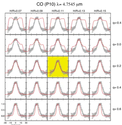
The CO P(10) line profile strongly depends on the surface den-sity power law exponent of the inner disk gas. In Fig.7, we dis-play the calculated CO P(10) line profile after taking the slit effects into account for disks with inner and outer disk H/R ranging from 0.07 to 0.15, and q ranging from−0.4 to +0.6.
The CO P(10) line profile is best described by slightly positive power-law surface density exponents, in other words, by a sur-face density that increases as a function of the radius. Power law exponentsq smaller than 0.0 produce line profiles that are too
broad, andq larger than+0.4 produce line profiles that are too
narrow. Keeping in mind the uncertainties and simplifications in the P
D
M
code, we can exclude gas surface density profileswith negative exponents for the inner disk. A steep surface den-sity profile with a negative exponent will assign too much gas to the inner few AU of the disk. This would result in too much hot CO gas close to the star emitting at high-velocities; hence, a broad line-profile (see upper row in Fig.7) that is inconsis-tent with the line profile and spectro-astrometric signal observed, which shows that the CO ro-vibrational emission comes from radii greater than a few AU.
This result is relatively independent of the scale height assumed for the inner disk. Here we have assumed that the CO 4.7µm line is produced entirely by disk emission. Although a contribution from a weak disk wind cannot be ruled out (the object displays asymmetric oxygen emission at 6300 Å, van der Plas et al. 2008), the symmetric spectro-astrometry sig-nature detected byPontoppidan et al.(2008) at three slit posi-tions favors a dominant contribution from disk emission.
Even though that all the cavity is filled with gas, the pre-dicted spectro-astrometry signature of our models is a factor 2 lower than the observations byPontoppidan et al.(2008), and the line flux is weaker than the line flux observed. Since we fit the line profile, the relative contributions to the flux by the dif-ferent radii should be correct. The missing flux might be related to a CO heating mechanism or CO physics not yet included in P
D
M
.5.3. Inner and outer disk scale height
We have set the scale height at the reference radius of 10 AU to be the same for the inner disk and the small dust grain compo-nent of the outer disk. In Fig.8b, we display the effect of chang-ing the scale height, the power law exponent of the surface den-sity of the inner disk, and the gas-to-dust ratio of the outer disk in the flux of the [O
] 63µm line.The [O
] 63 µm line flux changes little with a change inthe surface density of the inner disk, and is slightly sensitive to changes in the scale height of the inner and outer disk. In general, higher H/R values produce larger [O
] 63 µm fluxes.However, the mild sensitivity in the H/R of the outer disk is be-cause most of the gas mass in the outer disk is in its midplane layer that has lower H/R and large grains. Changes in the scale height of the small dust extended outer disk’s atmosphere change the [O
] 63µm line flux little because its mass is low withre-spect to that of the midplane.
H/R=0.07 H/R=0.09 H/R=0.11 H/R=0.13 H/R=0.15
q=-0.4
q= 0.0
q= 0.2
q= 0.4
-30 -15 0 15 30 V [km/s] 0.0
0.5 1.0
0.0
[N
orma
lize
d
Fl
ux
]
q= 0.6
[image:13.595.101.497.73.480.2]CO (P10)
= 4.7545 µ
m
Fig. 7. CO P(10) line profiles for diverse values of H/R and the surface density exponent of the inner diskqin the family of models 5. The
reference radius of H/R is 10 AU. H/R is the same for the inner and the outer disk. All other parameters of Model 5 are kept constant. The best fit is highlighted.
5.4. Outer disk’s gas-to-dust ratio
The fit to the SED provides a relatively robust estimate of the mass of mm-size grains in the outer disk. This value changed little in all the models tested and is on the order of 2×10⁻⁴ M.
The gas mass, hence the gas-to-dust ratio, in the outer disk is constrained by the simultaneous fit to the [O
] 63µm line fluxand the CO P(10) line profile.
Figure8b displays the flux of the [O
] 63µm as a functionof H/R for gas-to-dust ratios of the outer disk ranging from 1 to 100. We can see that the flux of the [O
] 63µm line is verysensitive to the value of the gas-to-dust ratio in the outer disk. We find that the [O
] 63µm line flux tends to be described bymodels with gas-to-dust ratios in the outer disk that are much lower than 100. Gas-to-dust ratios between 25 and 4 provide the best fit to line flux for the scale heights that are compatible with the SED.
In all the models, the [O
] 145 µm line flux is below theHerschelflux upper limits. In all the models, CO sub-mm lines
are so optically thick (τ >100 see Fig.6) that decreasing the gas mass does not affect the line fluxes, so these cannot be used to trace the gas mass.
The amount of gas in the inner rim of the outer disk influ-ences the shape of the CO P(10) profile, making it more centrally peaked when more gas is present in the outer disk (see Fig.8c). The best fit to the CO P(10) line is given by gas-to-dust ratios in the outer disk below 10.
The exact value of the gas-to-dust ratio in the outer disk is model dependent. However, since most of the models that si-multaneously describe the [O
] 63µm line flux, the SED, andthe CO P(10) line profile require gas-to-dust ratios for the outer disk that are smaller than 10, we believe that a gas-to-dust ratio much lower than 100 in the outer disk is a robust result.
Finally, the simultaneous modeling of the CO P(10) line pro-file and [O
] 63µm line flux favors models in which thegassur-face density contrast between the inner and the outer disk at the inner rim of the outer disk is less than a factor 20.
5.5. Inner disk’s gas mass, dust mass, and gas-to-dust ratio
For a given dust composition and size distribution, the SMA 870µm photometry upper limit of 10.5 mJy in a 34×70 AU beam