DESIGN AND DEVELOPMENT OF SOLAR POWERED BUCK CONVERTER USING MC34063 FOR 5V
*Adithya Ballaji
P.G. Student, Department of Electrical and Electronics Engineering, Reva University, Bangalore, Karnataka, India
ARTICLE INFO ABSTRACT
The evolution of Electronic gadgets and high performance electronic devices are primarily dependent on the battery of the device. Though with the advancement
difficult in remote places where electrification is still a distance dream and emergence of solar energy has paved way for the use of these electronic devices even in remote places. In this paper design and developme
presented. The built prototype is a low cost, compact, and portable with good efficiency which can be easily built for even general application. The hardware implementation
experimental results are presented in this paper.
Copyright © 2018, Adithya Ballaji and Akshith Monnappa permits unrestricted use, distribution, and reproduction
INTRODUCTION
The escalating demand and consumption of energy has just reached sky high due to developing technology and
population thus with the depleting reserves of conventional sources of energy. The dependence on renewable energy has been increasing to meet the demands of the world technology. And hence we can confirm that Renewable energy is here to stay, of the total installed capacity of 331.11GW in India, 31.7% constitutes to renewable energy. Of all the renewable energy’s available the solar energy is the most easily extractable and useable which is free and abundant in nature. With the availability and development of low cost solar panel there has been a rapid increase in the use of solar power in India. And with almost 300 days a calendar year of sun the use of solar power is more favorable. The installed solar capacity of India is 14.74GW. About 300 million people in India, which is about 25% of the population, have no electricity.
27% of power is lost in transmission or stolen and on an average the nation suffers from frequent power cuts of 10 hours daily. Thus with all these crisis related to
energy and its inability to reach remote location for transmission of power. And subsequent advancement of technology, the Smartphone and all the electronic devices have become part of day to day life. Most of these electronic
*Corresponding author:Adithya Ballaji,
P.G. Student, Department of Electrical and Electronics Engineering, Reva University, Bangalore, Karnataka, India.
ISSN: 0975-833X
Vol.
Article History:
Received 22nd November, 2017
Received in revised form
27th December, 2017
Accepted 29th January, 2018
Published online 28th February, 2018
Citation: Adithya Ballaji and Akshith Monnappa, K.
charging”, International Journal of Current Research
Key words:
MC34063, Solar, Charging and Buck Converter.
RESEARCH ARTICLE
DESIGN AND DEVELOPMENT OF SOLAR POWERED BUCK CONVERTER USING MC34063 FOR 5V
BATTERY CHARGING
Adithya Ballaji and Akshith Monnappa, K.
Electrical and Electronics Engineering, Reva University, Bangalore, Karnataka, India
ABSTRACT
The evolution of Electronic gadgets and high performance electronic devices are primarily dependent on the battery of the device. Though with the advancement of technology, it seems that it’s quite difficult in remote places where electrification is still a distance dream and emergence of solar energy has paved way for the use of these electronic devices even in remote places. In this paper design and development of a solar powered Buck Converter using MC34063 for 5V battery charging has been presented. The built prototype is a low cost, compact, and portable with good efficiency which can be easily built for even general application. The hardware implementation
experimental results are presented in this paper.
Akshith Monnappa. This is an open access article distributed under the Creative Commons in any medium, provided the original work is properly cited.
The escalating demand and consumption of energy has just reached sky high due to developing technology and growing population thus with the depleting reserves of conventional sources of energy. The dependence on renewable energy has been increasing to meet the demands of the world technology. And hence we can confirm that Renewable energy is here to e total installed capacity of 331.11GW in India, 31.7% constitutes to renewable energy. Of all the renewable energy’s available the solar energy is the most easily extractable and useable which is free and abundant in nature.
elopment of low cost solar panel there has been a rapid increase in the use of solar power in India. And with almost 300 days a calendar year of sun the use of solar power is more favorable. The installed solar capacity on people in India, which is about 25% of the population, have no electricity. And about 27% of power is lost in transmission or stolen and on an average the nation suffers from frequent power cuts of 10 Thus with all these crisis related to conventional energy and its inability to reach remote location for transmission of power. And subsequent advancement of and all the electronic devices part of day to day life. Most of these electronic
P.G. Student, Department of Electrical and Electronics Engineering,
devices require a 5V DC supply to charge there battery. paper a solar power Buck Converter us
mobile or battery charging has been designed and developed. The device is fed through a solar panel and has constant 5V output voltage. It is low cost and compact device and easy to build for general applications requiring 5V DC supply. application of the proposed system can be electric vehicle battery charging, mobile battery charging and general application requiring 5V DC supply. This paper contains the Software and hardware implementation with experimental results.
Literature Survey
The review of previous work on the development of solar powered charger is presented in this section. The Incitement and the problem are attained from the literature survey. The statement of problem and Summary of the literature is presented in this section. Several Solar charging systems have been proposed in the past, many of the past system developed
have incorporated a Discrete DC
microcontroller and Power control algorithm whereas someother system include developmen
battery charger for home power electronic systems which would require inverter to change DC to AC
2017). In (Florent Boico et al.,
for overcoming the changing environment during charging by incorporating MPPT technique and increasing the charging current is presented. In (Qutaiba Ali, 2010)
International Journal of Current Research
Vol. 10, Issue, 02, pp.65507-65511, February, 2018
Akshith Monnappa, K. 2018. “Design and development of solar powered buck converter using mc34063 for 5v battery Research, 10, (02), 65507-65511.
Available online at http://www.journalcra.com
z
DESIGN AND DEVELOPMENT OF SOLAR POWERED BUCK CONVERTER USING MC34063 FOR 5V
Electrical and Electronics Engineering, Reva University, Bangalore, Karnataka, India
The evolution of Electronic gadgets and high performance electronic devices are primarily dependent of technology, it seems that it’s quite difficult in remote places where electrification is still a distance dream and emergence of solar energy has paved way for the use of these electronic devices even in remote places. In this paper design and nt of a solar powered Buck Converter using MC34063 for 5V battery charging has been presented. The built prototype is a low cost, compact, and portable with good efficiency which can be easily built for even general application. The hardware implementation along with software and
Commons Attribution License, which
devices require a 5V DC supply to charge there battery. In this paper a solar power Buck Converter using MC34063 FOR 5V mobile or battery charging has been designed and developed. The device is fed through a solar panel and has constant 5V output voltage. It is low cost and compact device and easy to build for general applications requiring 5V DC supply. The application of the proposed system can be electric vehicle battery charging, mobile battery charging and general application requiring 5V DC supply. This paper contains the Software and hardware implementation with experimental
The review of previous work on the development of solar powered charger is presented in this section. The Incitement and the problem are attained from the literature survey. The problem and Summary of the literature is Several Solar charging systems have been proposed in the past, many of the past system developed
have incorporated a Discrete DC-DC Converter,
microcontroller and Power control algorithm (Ke Liu, 2009) whereas someother system include development of solar battery charger for home power electronic systems which would require inverter to change DC to AC (Pragnesh et al.,
et al., 2005) the controller algorithm
for overcoming the changing environment during charging by porating MPPT technique and increasing the charging (Qutaiba Ali, 2010) the use of Texas
INTERNATIONAL JOURNAL OF CURRENT RESEARCH
instruments based TPS63000 low power boost
Converter for charging is used while in some solar battery charger is mainly developed through microcontroller for measuring the voltage and switching of the battery
et al., 2016). An overvoltage protection circuit is developed
from protecting the battery from overcharging
et al., 2014). A boost converter is developed with current and
voltage controller for charging with USB port
2012). Driver controller along with PIC 16F684 for Smartphone charging has been developed (Jose Alfonso 2014). Summarizing, survey indicates that there is a need for a system which is less complex, compact and not bulky in design, which is portable and can be carried to remote location. The prototype presented here, easy to use and easy to design, the switching losses and system losses are minimized as system is less complex and very robust. Hence to achieve a cost effective, energy efficient system, to deliver optimum performance, a compact and portable system has been present in this paper.
Block Diagram
[image:2.595.47.272.407.449.2]The Figure 1 shows the block diagram of a Solar powered Buck Converter for 5V battery charging. It consists of a solar panel with charge controller, Buck converter and Battery for charging. The solar panel is used to convert the solar energy into electrical energy. Then the solar panel along with charge controller is used to power the buck converter and charge the 5V Battery. The buck converter is designed using the IC MC34063 and steps down the voltage from 12V to 5V.
Figure 1. Block diagram of Solar powered Buck Battery Charging
Solar panel
[image:2.595.327.541.489.664.2]The main objective of using the solar panel is to convert the solar energy into electrical energy and to power the buck converter. The whole world is now turning to solar power. There are two basic ways of connecting a solar panel which is either series or parallel to achieve the required output voltage and current.
Figure 2. Solar Panel
Table 1. Details of the Solar Panels
Rated Power 5W
Open circuit Voltage (Voc) 21.0V
Maximum Voltage (Vmp) 17.3V
Short Circuit Current (Isc) 0.63Amps
Maximum Power Current (Imp) 0.23Amps
65502 Adithya Ballaji and Akshith Monnappa, Design and development of solar powered buck converter using mc34063 for 5v battery charging 65508 Adithya Ballaji and Akshith Monnappa, Design and development
instruments based TPS63000 low power boost-buck DC-DC Converter for charging is used while in some solar battery through microcontroller for e and switching of the battery (Zar Ni Tun . An overvoltage protection circuit is developed from protecting the battery from overcharging (Rohit Kamble ed with current and port (Burak Akin, . Driver controller along with PIC 16F684 for (Jose Alfonso et al.,
Summarizing, survey indicates that there is a need for a ystem which is less complex, compact and not bulky in design, which is portable and can be carried to remote location. The prototype presented here, easy to use and easy to design, the switching losses and system losses are minimized as Hence to achieve a cost effective, energy efficient system, to deliver optimum performance, a compact and portable system has been present
shows the block diagram of a Solar powered Buck Converter for 5V battery charging. It consists of a solar panel with charge controller, Buck converter and Battery for charging. The solar panel is used to convert the solar energy n the solar panel along with charge controller is used to power the buck converter and charge the 5V Battery. The buck converter is designed using the IC MC34063 and steps down the voltage from 12V to 5V.
Figure 1. Block diagram of Solar powered Buck Converter for 5V
The main objective of using the solar panel is to convert the solar energy into electrical energy and to power the buck converter. The whole world is now turning to solar power. nnecting a solar panel which is either series or parallel to achieve the required output voltage
Table 1. Details of the Solar Panels
21.0V 17.3V 0.63Amps 0.23Amps
There are different types of solar panels based on the level of silicon purity. Here a BMES SSI5W 5W Polycrystalline type solar panel is used shown in Figure 2. The solar panel used supplies a 12V input to the buck converter. The details of the panel are mentioned in table 1 below.
Buck Converter
The buck converter used here has an input voltage of 12V and output voltage of 5V. Here MOSFET is not
device and instead IC MC34063 is used which is a step up / step down / inverting switching regulator.
Battery
A battery is a device which is used to store energy. The capacity of a battery is termed as Amp
The rate of charging and discharging is expressed as “C The energy from solar which is converted from solar energy to electrical energy is stored in 5V Battery. There are basically two types of battery namely rechargeable and non rechargeable. The ones which
called as rechargeable battery where as those which can be used only once are called as non
is used in almost all electronic devices including mobiles.
MC34063
IC MC34063 is basically a 1.5A st
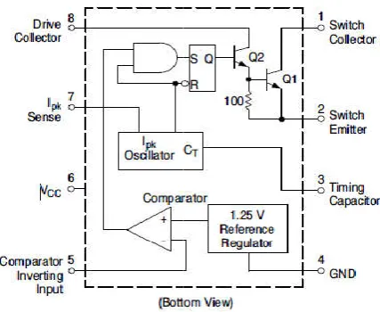
regulator. It incorporates a monolithic circuit mainly for the DC-DC Converter operation. The schematic diagram is as shown in figure 3 below. It embodies an inbuilt temperature compensated reference, controlled duty cycle oscillat
active, current limit circuit, comparator, driver and high current output switch. It has working range of 3.0V to 40V and an operating frequency of 100 kHz with a precision of 2 %. Some of the features of MC34063 are mentioned below:
Figure 3. Schematic Diagram
Operating range can vary from 3.0 V to 40 V Input
It has a very low standby current
Current Limiting is inbuilt
Has a 1.5 A of output current
Output voltage adjustable
Has a 100 kHz of operational frequency
Precision of about 2% f
It is available in Pb−Free Packages
Design and development of solar powered buck converter using mc34063 for 5v battery charging Design and development of solar powered buck converter using mc34063 for 5v battery charging
There are different types of solar panels based on the level of silicon purity. Here a BMES SSI5W 5W Polycrystalline type in Figure 2. The solar panel used supplies a 12V input to the buck converter. The details of the panel are mentioned in table 1 below.
The buck converter used here has an input voltage of 12V and output voltage of 5V. Here MOSFET is not used as switching device and instead IC MC34063 is used which is a step up / step down / inverting switching regulator.
A battery is a device which is used to store energy. The capacity of a battery is termed as Amp-hours or m A-hours. f charging and discharging is expressed as “C-Rate”. The energy from solar which is converted from solar energy to electrical energy is stored in 5V Battery. There are basically two types of battery namely rechargeable and non-rechargeable. The ones which can be used more than once are called as rechargeable battery where as those which can be used only once are called as non-rechargeable. Li-ion Battery is used in almost all electronic devices including mobiles.
IC MC34063 is basically a 1.5A step up/down and inverting regulator. It incorporates a monolithic circuit mainly for the DC Converter operation. The schematic diagram is as shown in figure 3 below. It embodies an inbuilt temperature compensated reference, controlled duty cycle oscillator with an active, current limit circuit, comparator, driver and high current output switch. It has working range of 3.0V to 40V and an operating frequency of 100 kHz with a precision of 2 %. Some of the features of MC34063 are mentioned below:-
3. Schematic Diagram
Operating range can vary from 3.0 V to 40 V Input It has a very low standby current
Current Limiting is inbuilt Has a 1.5 A of output current Output voltage adjustable
Has a 100 kHz of operational frequency
Precision of about 2% for reference is achievable −Free Packages
[image:2.595.57.271.571.713.2]Buck Converter Using MC34063
[image:3.595.51.275.240.329.2]Here in this section the operation of a buck converter is explained, assuming that the transistor Q1 is off, shown in below figure 4. The inductor current (IL) is zero and the voltage at the output is at its nominal value. The voltage across capacitor Cout that is the output voltage will ultimately decay below the nominal output level, since it is the only available source of supply current to load RL. This voltage scarcity is sensed by the switching mechanism and control circuit and leads Q1 to turn on. Thus the inductor current starts to flow from Vin through Q1 and Cout in parallel with RL, and it rises at a rate of ΔI/Δt = V/L. The voltage across the inductor is equal to Vin – Vsat – Vout, and the inductor peak current at any instant is calculated as shown here:
Figure 4. Circuit Diagram of buck converter
IL = ((Vin – Vsat – Vout)/L)t
After the end of the on period, thus Q1 is turned off. Soon the magnetic field in the inductor starts to collapse, hence generating a reverse voltage that makes D1 forward biases, and the peak current reduces at a rate of ΔI/Δt = V/L as energy is supplied to Cout and RL. The voltage across the inductor during this period is equal to Vout + VF of D1. Where VF is the forward voltage of D1.The current as a function of time is calculated as shown here:
IL = IL (pk) – ((Vout + VF)/L)t
Thus a buck converter is designed and developed using MC34063 and is shown in the below figure 5. It consist of an input and output capacitor with a current limiting resistor.
Figure 5. Circuit Diagram of buck converter using MC34063
The IC based reduces the size of the circuit making it compact, switching losses are reduced, the need for MOSFET for switching is eliminated in turn the need for controller for generating external pulses for the switch is also eliminated hence making the circuit compact, efficiency is high and reliable.
65509 International Journal of Current Research,
[image:3.595.310.557.460.581.2]Here in this section the operation of a buck converter is explained, assuming that the transistor Q1 is off, shown in below figure 4. The inductor current (IL) is zero and the voltage at the output is at its nominal value. The voltage across that is the output voltage will ultimately decay below the nominal output level, since it is the only available source of supply current to load RL. This voltage scarcity is sensed by the switching mechanism and control circuit and us the inductor current starts to flow from Vin through Q1 and Cout in parallel with RL, and it rises t = V/L. The voltage across the inductor is Vout, and the inductor peak current at
Figure 4. Circuit Diagram of buck converter
After the end of the on period, thus Q1 is turned off. Soon the magnetic field in the inductor starts to collapse, hence generating a reverse voltage that makes D1 forward biases, and t = V/L as energy is to Cout and RL. The voltage across the inductor during this period is equal to Vout + VF of D1. Where VF is the forward voltage of D1.The current as a function of time is
designed and developed using MC34063 and is shown in the below figure 5. It consist of an input and output capacitor with a current limiting resistor.
Figure 5. Circuit Diagram of buck converter using MC34063
The IC based reduces the size of the circuit making it compact, switching losses are reduced, the need for MOSFET for switching is eliminated in turn the need for controller for generating external pulses for the switch is also eliminated circuit compact, efficiency is high and
Design Specification
Vinput =12V, Voutput = 5V, V
675mA
C1= 100µF/16V, CO= 50µF/16V CT= 220pF, Ceramic
R1= 1K,1/4W,5%
R2= 3K,1/4W,5%
RSC= 0.22E, 2W, 5% LMIN= 25µH
F= 85 KHz
Simulation Results
The LTspice circuit of the system is shown in the figure 6. Below. And the output current and output voltage waveforms are shown in the figure 7 and figure 8 respectively. To simulate PV panel, Voltage sourse (V1) and series resistance (Rser) are used as input to the system with 12V DC and output generated is 5V DC. As it can be seen from the simulation circuit there is no need for an external controller for providing PWM pulses to the switch,there by eliminating the need for switch and aexternal controller, which inturn makes the circuit compact and less bilky. The simulation model can be used to analyze the effect of changing values of certain components, and provide a reference for components selection.
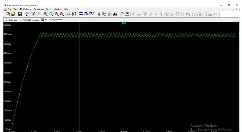
waveform in figure 6 shows the output current, which reaches a maximum value of 500 milli
waveform there is no sudden current spikes in the output and is in constant and steady state, with some amount of ripple. above waveform in figure 7 shows the
reaches a maximum value of 5V. As seen from the waveform there is no sudden voltage spikes in the output and is in constant and steady state, with some amount of ripple.
Figure 6. Simulation of buck converter using MC34063 in LTs
Hardware Results
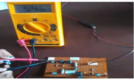
Here a prototype has been designed and developed on the general PCB board as shown in the figure 8 below. It mainly consist of an current limiting resistor, input and output capacitor and MC34063 IC. Experiments have been conducted on the prototype and firgure 9 below shows the results. from the results it can be seen that the the converter is able to generate an output voltage of 5V constantly for charging. The input to the converter is supplied through solar panel. above figure 8 shows the buck converter prototype for battery charging using MC34063 IC.
capacitor on th input and output these capacitor are used for transient stability and to avoid ripple at the output.
International Journal of Current Research, Vol. 10, Issue, 02, pp.65507-65511, February, 2018
= 5V, Vripple = 50mV/pp, IO=
= 50µF/16V
The LTspice circuit of the system is shown in the figure 6. Below. And the output current and output voltage waveforms are shown in the figure 7 and figure 8 respectively. To simulate PV panel, Voltage sourse (V1) and series resistance (Rser) are used as input to the system with 12V DC and output generated is 5V DC. As it can be seen from the simulation circuit there is no need for an external controller for providing PWM pulses to the switch,there by eliminating the need for aexternal controller, which inturn makes the circuit The simulation model can be used to analyze the effect of changing values of certain components, and provide a reference for components selection. The above shows the output current, which reaches a maximum value of 500 milli-Amps. As seen from the waveform there is no sudden current spikes in the output and is in constant and steady state, with some amount of ripple. The above waveform in figure 7 shows the output voltage, which reaches a maximum value of 5V. As seen from the waveform there is no sudden voltage spikes in the output and is in constant and steady state, with some amount of ripple.
Figure 6. Simulation of buck converter using MC34063 in LTspice
Here a prototype has been designed and developed on the general PCB board as shown in the figure 8 below. It mainly consist of an current limiting resistor, input and output capacitor and MC34063 IC. Experiments have been conducted on the prototype and firgure 9 below shows the results. And from the results it can be seen that the the converter is able to generate an output voltage of 5V constantly for charging. The input to the converter is supplied through solar panel. The igure 8 shows the buck converter prototype for battery charging using MC34063 IC. There are two electrolytic capacitor on th input and output these capacitor are used for transient stability and to avoid ripple at the output.
[image:3.595.38.289.552.690.2]Figure 8. Prototype of the designed Buck
[image:4.595.57.537.52.314.2]65510 Adithya Ballaji and Akshith Monnappa, Design and development of solar powered buck converter using mc34063 for 5v battery charging
[image:4.595.78.507.469.759.2]Figure 6. Output Current waveform
Figure 7. Output voltage waveform
Figure 8. Prototype of the designed Buck converter for battery charging
Design and development of solar powered buck converter using mc34063 for 5v battery charging
converter for battery charging
Figure 9. Output voltage
As it can be seen the converter is very compact and less bulky, there is no need of an external circuit for the PWM signal thus eliminating the need of external circuit. The output voltage is shown in the above figure 9 and can be seen that the converter is able toproduce a output voltage of 5V and input is supplied through solar panel.
Conclusion
The future belongs to renewable energy, and especially to solar energy. Here a solar powered buck converter is designed and developed using MC34063 for 5V battery charging. The simulation and hardware results have been presented in earlier section. The built prototype can be used for charging batteries for portable electronic devices. Such as mobile batteries, toy batteries, flashlight batteries and as a power source for devices in laboratory and for devices requiring 5V supply. The prototpe has various advantages like it is cost effective, multifaceted, uninterrupted power supply and can be used in remote location where electricity and power is still a distant dream.
REFERENCES
Adithya Ballaji, Akshith Monnappa and Harshitha G.B. 2017. “Design and development of boost converter using MC34063 for DC input LED driver” IJIRSET, Volume 7, Issue 2, February
Burak Akin, 2012. “Solar Powered Charger with Universal
USB Output “IEEE
Dhanil Vira, Mandeep Singh Saini and Uday Rote. 2015. “Android battery manager application and a solar based portable mobile charger” International Journal of Research
in Advent Technology, Vol.3, No.3, March E-ISSN:
2321-9637
Florent Boico, Brad Lehman and Khalil Shujaee. 2005.“Solar Battery Chargers for NiMH battery” IEEE. Jose Alfonso, Omar Garcia, Caroina Tripp and Sanjay Misra.
2014 “A low cost solar cell charger prototype for
Smartphone’s battery charging” Adaptive Science &
Technology (ICAST), 2014 IEEE 6th International
Conference, Oct
Ke Liu, 2009, Member IEEE, John Makaran, member IEEE, “Design of a solar powered battery charger” IEEE
Electrical Power and Energy Conference.
Liping Guo, Andrew Brewer and Brett Speiser. 2010.“design and implementation of a solar battery charger” ©
American Society for Engineering Education.
Pragnesh, Digvijay, Chirag and Prof. Jaydipsinh. 2017. “Solar battery charger” International Journal of engineering
development and research.
Qutaiba Ali, 2010. IEEE Member, “Design and
Implementation of a mobile phone charging system based on solar energy harvesting” International Conference on Energy, Power and Control
Rohit Kamble, Sameer Yerolkar, Dinesh Shirsath and Bharat
Kulkarni. 2014. “Solar Mobile Charger” International
Journal of Innovative Research in Computer Science and
Technology.
Su Sheng, Chung-Ti Hsu, Peng Li, and Brad Lehman. “Energy Management for solar battery charging station”
Thanyanut Lueangamornsiri, Warit Wichakool and Kusumal Chalermyanont. 2017. “Solar battery charger using a
multistage converter” IEEE Regional Symposium on Micro
and Nanoelectronics (RSM)
Zar Ni Tun, Aye Thin Naing and Hla Myo Tun. 2016.“Design and Construction of Microcontroller Based Solar Battery Charger” International Journal of scientific and technology
research.