Deployment and Evaluation of IEEE 802.11
based Wireless Mesh Networks in Campus
Environments
Abstract: - The traditional wireless networks cannot handle new requirements posed on the system. To become independent of backbone networks leading to cheap deployments, the traditional single-hop approach needs to be replaced by its multihop counterpart called Wireless Mesh Networks (WMNs). They can be considered as hybrid between wireless infrastructure (WLAN) and ad-hoc networks (MANET). WMNs provide flexibility and scalability in building networks, allowing automatic discovery of neighboring nodes, increased reliability and redundancy. In this paper we discuss as to how WMNs can be practically deployed to support wireless multihop communications in a campus-wide area. The main aim of the testbed is to evaluate state-of-the-art, off-the-shelf technology for WMNs. The main contribution of this work is: to report our experience in deploying a real WMN testbed and performing a preliminary analysis of the performance of this kind of technology for campus use. Such a WMN can be easily extended for other applications such as community use, enterprises; e.t.c. Currently the network is being used to provide services to the residential areas of the campus.
Keywords:- Wireless Mesh Network; testbed; IEEE 802.11s draft; performance evaluation
Manuscript received March 05, 2011; revised April 15, 2011. This work is done in Cyber Security Research Center (CSRC) located at PEC University of Technology. The authors would like to thank Government of India, Ministry of Communications and Information Technology, Department of Information Technology, New Delhi, for funding the Project “Design and Development of Dependable, Secure and Efficient Protocol for Wireless Mesh Network(WMN)”, under which part of the work mentioned in the paper has been carried out.
1Divya is Asst.Professor in Computer Science & Engineering, PEC University of Technology, Chandigarh. INDIA, (email: [email protected], Phone : +91 172 2753853)
2 Sanjeev Sofat is Professor in Computer Science & Engineering, PEC University of Technology,Chandigarh. INDIA
3 Puneet Chawla is Asst.Pprofessor in Electrical Engineering, PEC University of Technology
4 Prafulla Kumar is Director at Department of Information Technology, Ministry of Communication & Information Technology, New Delhi, INDIA.
I. INTRODUCTION
The tremendous success of the Institute of Electrical and Electronics Engineers (IEEE) 802.11 Wireless Local Area Network (WLAN) standard led to severe competition. IEEE 802.11 became a universal solution for wireless connectivity. However, WLAN still depends on wired infrastructure that interconnects the central Access Points (APs). Wireless Mesh Networks (WMN) is an emerging two-tier architecture targeting the deployment of large-scale networks in a fast and inexpensive manner. Wireless mesh networks have drawn a lot of attention in various market segments, including home and small business networks, medium and large enterprise networks, public safety, emergency and first-responder networks, service providers and wireless broadband networks, municipal and public access networks, and military and tactical networks. The WLAN mesh networking task group at IEEE codenamed TGs has reached the draft specification stage, where security specification is now essential. IEEE 802.11s (TG since May 2004) is a draft IEEE 802.11 amendment for mesh networking, defining how wireless devices can interconnect to create a mesh network. IETF did set a mesh networking TG to standardize IEEE 802.11s and the work is still in progress. The draft defines setting of auto configuring paths at MAC layer between stations over self configuring multi hop topologies using radio aware metrics and automatic topology learning. It allows for alternative path selection metrics and protocols and permits both reactive and proactive mode. Even though the standard is not final yet, the main traits of the standard have been already set which includes IEEE 802.11s architecture and routing using MAC addresses. WMNs are multi-hop wireless networks formed by mesh routers and mesh clients. These networks typically have a high data rate and low deployment and maintenance overhead. Mesh routers are generally stationary and do not have energy constraints, but the clients may be mobile or stationary and may therefore be energy constrained. Mesh routers which are connected to the Internet through a wired backbone are designated as gateway routers. A gateway router provides access to conventional clients and interconnects other networks to the Internet. A mesh network can provide multi-hop communication paths between wireless clients, thereby serving as a community network, or can provide multi-hop paths between the client and the gateway router, thereby providing broadband Internet access to clients. As there is no wired infrastructure to deploy in the case of WMNs, they are considered cost-effective alternatives to
WLANs (wireless local area networks) and backbone networks to mobile clients.
WMNs are important for distributed applications that cannot rely on a fixed infrastructure, but require instant deployment, dynamism, self-configuration and self-organization [1, 2].
However to explore the full potential and limitations of this new technology, we have deployed a realtime testbed for multi-hop WMNs using the Orinoco mesh creation protocol (OMCP) which is the part of Orinoco 4000MR-LR mesh device.
The main contribution of this paper is reporting our experiences of deploying a real Wireless Mesh Network which is used as a testbed for validation of experimental results and is also used to offer services to campus residentials.
II. INFRASTRUCTURE OF WMN
Wireless mesh network are able to extend the network without any infrastructure by using the multihop wireless connections between AP’s. Various types of nodes used in WMN are described as follows [5,10]:
A. Mesh Point (MP):- MP which provides mesh services, can be a dedicated infrastructure device enabled to fully participate in the network. It can relay messages in ad-hoc fashion on behalf of other MPs to create a self-configuring system that extends the coverage range and increase the available bandwidth.
B. Mesh Access point (MAP):- A special type of MP which provides the AP services in addition to mesh services provided by MPs.
C. Mesh Portal Point (MPP):- A special MP that serves as a gateway to a wired network, it supports transparent bridging, address learning and bridge-to-bridge communication.
D. Station (STA):- STA is totally mobile user device and does not participate in mesh services; it communicates with other stations via an AP, a MAP, or an MPP.
WMNs may connect to the internet via MPP and MPs work as wireless bridges within WMN. They facilitate the connectivity and intercommunication of wireless clients through multihop wireless paths. MPs in WMNs are often stationary and not power-constrained, thus freeing routing protocols from the burden of dealing with mobility and power constraints [3].
A peculiar feature of WMNs is that, if the source and the destination are not in the same Basis Service Set (BSS) domain, the source MAP does not forward packets to all the MAPs in the Extended Service Set (ESS), instead the packets are sent via MPs to reach the destination.
III. RELATED WORK
University of California, Santa Barbara Mesh Testbed [4, 5] is an experimental wireless mesh network consisting of nodes equipped with multiple IEEE802.11a/b/g wireless radios and distributed on various floors of a campus building. The aim of this testbed is to test new protocols supporting robustness in multihop wireless networks. The Broadband and Wireless network (BWN) lab at Georgia institute of Technology [5, 9, 10] has also built a WMN testbed. The testbed includes 15 IEEE802.11b/g based mesh
routers, some of which are wireless gateways connected to the internet. The testbed is distributed among various rooms on a single floor. It has flexible configuration and topology. The aim of this WMN testbed is to investigate and evaluate routing and transport protocols for WMNs. It integrates with existing wireless sensor network. MAP at Purdue is an experimental WMN testbed [5] composed of several nodes capable of running in both 802.11a and 802.11b/g mode. Purpose of this testbed is to study routing problems and solutions to create high throughput routes. Carleton University [4] has set up a general purpose WMN testbed using Intel IXP425 series Xscale network processors working as routers and iPAQ as clients. Two WLAN network interfaces are installed on the two Mini-PCI slots, one is a Prism 2/2.5 card, which supports IEEE 802.11b, and the other is an Atheros card, which supports IEEE 802.11a/b/g. MIT Roofnet [7] consists of about 50 nodes in apartments in Cambridge, MA. Each node is in radio range of a subset of the other nodes, and can communicate with the rest of the nodes via multi-hop forwarding. A few of the nodes act as gateways to the wired Internet. The longest routes are four hops long. The main aim of setting up of this testbed was to evaluate the performance of multi hop networks for community use with real users. The research focuses on link layer measurements and routing protocols. It uses open source software which runs on Intersil Prism 2.5 or Atheros AR521X based hardware. Skypilot network [8] is another industry based testebed is based in Santa Clara, CA, USA. The major application of the testbed is broadband Internet access. It uses high power radio with multiple directional antennas. It is based upon link quality and hop count based proprietary routing and Dynamic bandwidth scheduling. It also has Dual band with 2.4GHz for users, 5GHz for backhaul.
IV. NEED AND ANALYSIS OF DEPLOYING WMN IN
THE CAMPUS
determining the best route over multiple hops to follow their characteristic of being self-configuring and self-healing. The Mesh APs use the ORiNOCO Mesh Creation Protocol (OMCP) for creating wireless mesh network. The formation of a Proxim ORiNOCO mesh network begins as soon as the Wi-Fi cell is turned on. Wi-Fi cells cannot sense that they have a direct network connection and hence begin an automatic discovery process. Secure links to the other mesh APs are created using secure AES encryption and authentication which was enabled as a part of deployment. The routing protocol (OMCP) then determines the most efficient path through the mesh, taking into account the traffic load, link speed, signal strength, number of hops and other parameters. Based on this calculation, specific routes from each mesh AP to mesh portal APs are set up. The route configuration can also be static where the routes are obvious and the size of mesh network is very small such that scope of failover is hardly there. In addition to serving as an experimental testbed, the wireless mesh network is also being used for providing wireless connectivity to the residential areas of faculty of the campus. Such a mesh can also be replicated for other solutions such as wireless video surveillance in nearby cities, WISPs, and city-wide wireless networks.
V. ARCHITECTURAL DESIGN OF TESTBED
In this section, we describe the main devices used for setting up our testbed and motivate our choice. Proxim’s ORINOCO 4000MR-LR mesh AP’s [12] has been used for the deployment of the wireless mesh network. For the centralized authentication RADIUS [13] has been used which is integrated with the Active directory. While active directory itself is not an authentication system, it is used as centralized account storage mechanism. Microsoft’s Protected EAP [14] has been used as the network authentication protocol.
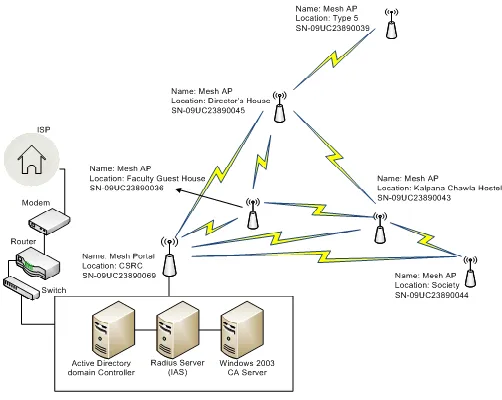
The ORiNOCO 4000MR-LR Mesh AP’s uses the ORiNOCO Mesh Creation Protocol (OMCP) that allows creation of self-forming and self-healing non-line of sight mesh networks [12]. Fig 1 shows the view of our network setup. A total of six mesh capable devices including MPs and MPP are part of our wireless mesh network. Amongst them there one mesh portal has been configured and the rest five are configured as mesh AP’s. The mesh portal is connected to the internet through radius server. In our case Mesh portal is capable to act as both a portal as well as a mesh point. A large number of clients get connected to the mesh portal as well as mesh AP’s for accessing internet services. Salient characteristics of Proxim's mesh products include: a dual-radio configuration, increasing system capacity by allowing one radio to focus on Wi-Fi access and the other radio to perform mesh backhaul duties; Quality of Service (QoS) enabling voice and video capability; and enterprise-class security features. If a mesh link becomes obstructed, client traffic is dynamically re-routed, ensuring uninterrupted video streams and voice calls. Other interesting features of the Proxim Orinoco mesh points which were considered are simultaneous 802.11b, 802.11g & 802.11a support, IEEE 802.1x and 128-bit AES support for authentication and encryption methods including mutual
authentication, message integrity check, per packet keys initialization vector hashing and broadcast key rotation, detection of alerts and unauthorized rogue access points and clients in both the 2.4 GHz and 5 GHz bands, automatically receiving correct configuration by new AP’s and preventing security vulnerabilities.
In the next section we report the process of getting authenticated and hence connected to the WMN. As per the WMN architecture represented in the Fig 1 the working of wireless mesh network given below:
I.Wireless Client PC/laptop sends request to connect to Mesh AP
II.The Mesh AP which is configured to use RADIUS [13] as the authentication, authorization, and accounting protocol and receive request of client creates an Access-Request message and transmits it to the Mesh Portal. III.The Mesh Portal forwards the user’s request message to
RADIUS Server.
IV.The Radius server evaluates the user’s Request message. V.If required, the Radius server sends a Challenge message to
the Mesh Portal. The Mesh Portal processes the challenge and sends an updated user’s request to the Radius server. VI.The user credentials are checked and the dial-in properties
of the user account are obtained by using a secure connection (PEAP) to a domain controller.
VII.If the Credentials verified by the Domain Controller are found correct, then the Radius server allows the user to connect.
VIII.After the successful connection the client is able to access the Internet through the Wireless Mesh Network.
VI. WMN TESTBED DEVELOPMENT
[image:3.612.308.559.186.386.2]In this section we describe the real time deployment which also acts as a secure testbed; both for offering services and also for conduct of experiments. We have build WMN testbed at PEC University of Technology campus, under the Cyber Security
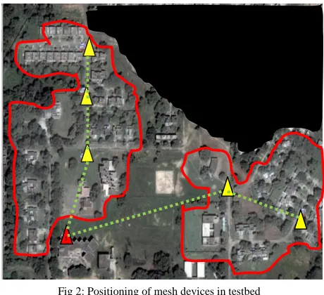
Research Center, Chandigarh. The google map of residential area of the campus in Fig 2 shows the actual positioning of mesh devices. The areas marked with red line in Fig 2 indicate the areas of interest where there was no connectivity existing.
The total area covered by the current WMN spans over 1000x700 sq mts. Shaded triangles in Fig 2 depict the position of the mesh points. The red triangle depicts the position of the mesh portal. The location of the mesh portal was chosen based upon the last mile wired connectivity that was available in the campus. Beyond this point wired connectivity did not exist in any form. The mesh points on the mesh backbone are operating on 5 GHz, 8dBi, while the clients are communicating with the mesh AP’s on 2.4GHz, 8
dBi. The mesh backbone is implemented using 5Ghz radio‘s that is mounted on ORiNOCO Mesh AP’s, where as clients may be any wireless device such as laptop,PDA etc. The rationale behind this choice is that of keeping these two frequencies far from each other so as to prevent the interference that could affect the performance of the network. Distance between the mesh AP’s have been chosen such that the neighboring mesh AP’s can get better connectivity with each other so as to maintain mesh backbone. Fig 3 shows the pictures of the actual mesh points and the mesh portal being deployed in the network. All the MPs and MPP have been weather protected to provide protection against the climatic changes. Since the power supply already existed in the form of street light poles and hence the existing light poles were being used for ease of installation.
VII. EXPERIMENTAL DESIGN & RESULTS
We used the Netstumbler [11] tool running on a Windows laptop equipped with a wireless IEEE 802.11g based PCI card to take signal strength measurements at various locations around the campus. To measure throughput, packet loss and latency, Iperf 2.0.4 [16] has been used. It is a simple, readily-available tool that measures TCP/UDP throughput, loss, and delay over any kind of IP network, including local Ethernet LANs, Internet access links, and Wi-Fi networks. The TCP and UDP traffic was generated using Iperf and the packet sizes were varied
to measure various metrics. Two components were installed: an IPerf server which listens for incoming experimental requests and an IPerf client which launches test sessions. IPerf server and client are both installed on Wi-Fi laptops. By default, IPerf
clients establish a single TCP session to the IPerf server listening
[image:4.612.316.565.106.272.2]1
Fig 2: Positioning of mesh devices in testbed
Fig. 3(a): wireless mesh portal connected through Ethernet
Fig. 3(b) Mesh Point mounted on street pole
Fig. 3(c) Mesh Point mounted on street pole
2.4Ghz antenna for client access
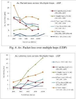
[image:4.612.50.280.204.414.2] [image:4.612.316.566.305.485.2] [image:4.612.317.565.516.694.2]to Port 5001 at the specified destination. For our experiment for TCP based traffic we set a time interval of 5 minutes, default TCP window size of 8 Kbyte and five data packets which vary for size 200 Byte, 400 Byte, 600 Byte, 800 Byte, 1000 Byte for each time interval resulting to a total duration of 25 minutes. For UDP based traffic also we set a time interval of 5 minutes, however Bandwidth is set to 145 Kbps and five data packets are sent which vary for size 200 Byte, 400 Byte, 600 Byte, 800 Byte, 1000 Byte for each time interval resulting to a total duration of 25 minutes. Medium-size frames, such as the 400-byte packets have been used in the experiments because they are close to the "average" Internet size. Long packets, such as the 1000-byte packets are used to stress a network. With long packets, the ratio between packet payload and packet headers is higher which can be used to quickly fill up the packet queue with longer packets. To perform the experiment on WMN testbed across various hops, the Internet services were disconnected. This was being done after notifying the users that the Internet Services will be unavailable for certain duration of time. It is important to do so, since the performance had to be done at various hops and in case the users were connected to WMN, the traffic of each Mesh Point would be highly unpredictable and hence lead to incorrect results. It is pertinent to mention that at the time when measurements were performed at single hop, the traffic was not sent from mesh points across three hops and two hops. Similarly when the measurements were performed at two hops, traffic wasn’t sent across three hops. Fig 4 & 5 show the average packet loss and average latency over multiple hops for UDP traffic respectively. It can be observed that in general that the packet loss and latency increase with more no. of hops. This can be attributed to the fact that since packets have to communicate over multiple hops, they get queued up at various hops causing erroneous data flows and delays. Further it can be observed that packet losses over S-Single hop (shaded route) are more than C-Single hop (clear) as S-Single hop was obstructed by trees even though the distance of S-single hop is shorter than C-Single hop. While the latency in case of C-Single hop is observed to be much more in comparison to S-Single hop. It can also be inferred that smaller sized UDP packets such 200 bytes cause higher packet losses at multiple hops. This could be due to the fact that when smaller sized packets have to route though multiple hops, they stress a device. Multiple hops implies more no. of devices thereby icreasing losses. Fig 6 depicts average throughput over multiple hops with TCP traffic. It can be observed that portal is showing the best throughput and wireless mesh point which is three hops away is showing lower throughput. It can also be observed that single hop mesh points favour medium and large size packets while mesh points which are multiple hop away favour medium sized packets as small and large size packets stress up the devices and the network respectively.
VIII. CONCLUSIONS
In this paper we discuss as to how WMNs can be practically deployed to support wireless multihop communications in a campus-wide area. The main aim of the testbed is to
evaluate state-of-the-art, off-the-shelf technology for WMNs. The main contribution of this work is: to report our experience in deploying a real WMN testbed and performing a preliminary analysis of the performance of this kind of technology for campus use. In addition, we describe some initial results of performance characteristics measured over multiple hops over our testbed. The measurement results presented in this paper are very preliminary. The main aim of the project under which the
[image:5.612.303.564.147.487.2] [image:5.612.308.565.516.691.2]testbed has been setup is to design and develop security Fig. 5: Av. Packet latency over multiple hops (UDP)
Fig. 4: Av. Packet loss over multiple hops (UDP)
enhanced routing protocols and to use testebed to demonstrate that security attacks are actually practical to implement.
ACKNOWLEDGMENT
This work is done in Cyber Security Research Center (CSRC), PEC University of Technology. The authors would like to thank Government of India, Ministry of Communications and Information Technology, Department of Information Technology, New Delhi, for funding the Project “Design and Development of Dependable, Secure and Efficient Protocol for Wireless Mesh Network(WMN)”, under which this research work has been done.
REFERENCES
[1] Microsoft Research, Self-Organizing Neighbourhood Wireless Mesh Networks, In T. Imielinski and H.Koth, editors, Mobile Computing, Kluwer, 1996.
[2] K.R Chowhury, I. F. Akyildiz,” Cognitive Wireless Mesh network with Dynamic Spectrum Access,” IEEE Journal on selected Area in Communications, vol 26, no 1 pp 168-181, Jan 2008.
[3] Richard Draves, Jitendra Padhye, Brain Zill, Routing in Multi-Radio, Multi-Hop Wireless Mesh Networks, in Proceedings of ACM MobiCom’04.
[4] University of California Santa Barbara, UCSB MeshNet, http://moment.cs.ucsb.edu/meshnet/.
[5] Ali Hamidian, Claudio E. Palazzi, Tin Y. Chong, Juan M. Navarro, Ulf Körner, Mario Gerla ”Deployment and Evaluation of a Wireless Mesh Network”, Second IEEE International Conference on Advances in Mesh Networks, 2009 pp 66-72.
[6] D.Koutsonikolas, J. Dyaberi, P. Garimella, S. Fahmy, Y. C. Hu,” On TCP throughput and Window Size in a Multihop Wireless Network Testbed,”in Proc. of ACM Mobicom International Workshop on Wireless Network Testbeds, Experimental evaluation and Characterization (WiNTECH 07) , Montreal, QC,Canada, Sep 2007.
[7] J. Bicket, D. Aguayo, S. Biswas, , and R. Morris, Architecture and evaluation of an unplanned 802.11b mesh network,Ž in Proceedings of the 11th annual international conference on Mobile computing and networking
(MOBICOM), ologne, Germany, Sept. 2005.
[Online].http://pdos.csail.mit.edu/roofnet/doku.php. [8] Project Details available Online at: www.skypilot.com
[9] Project Details available Online at:
http://www.ece.gatech.edu/research/labs/bwn/mesh/testbed. html
[10]D.Koutsonikolas, J. Dyaberi, P. Garimella, S. Fahmy, Y. C. Hu,” On TCP throughput and Window Size in a Multihop Wireless Network Testbed,”in Proc. of ACM Mobicom International Workshop on Wireless Network Testbeds, Experimental evaluation and Characterization (WiNTECH 07) , Montreal, QC,Canada, Sep 2007.
[11]Marius Milne, NetStumbler v0.4.0 Release Notes Avaliable
Online at URL:
http://downloads.netstumbler.com/downloads/netstumbler_ v0.4.0_release_notes.pdf
[12] Details available in datasheet, URL:
http://proxim.com/downloads/products/ap_4000/ds_ap-4000_a4.pdf
[13]C. Rigney, S. Willens, A. Rubens, W. Simpson, "Remote Authentication Dial In User Service (RADIUS)", RFC 2865, June 2000
[14]Microsoft,Securing Wireless LANs with PEAP and Passwords, June 2007,pp 59-66 Available Online at :http://technet.microsoft.com/en-us/library/dd162271.aspx [15]Project Details available Online at PEC website URL:
http://pec.ac.in/scripts_new/csrc_wireless09.asp [16]www.iperf.darwinports.com/