Symmetry-Based Pulse Sequences in Solid–State
NMR and Applications to Biological Systems
Xin Zhao, Marina Carravetta, P.K.Madhu, and Malcolm H.Levitt
March 18, 2003
†Department of Chemistry, University of Southampton, Southampton
SO17 1BJ , UK
Abstract
We present some applications of solid–state nuclear magnetic resonance to
model compounds and biological systems. We highlight a class of pulse
sequences that are designed based on symmetry properties of the internal
spin interactions. Examples are given showing resonance assignments,
de-termination of internuclear distances, and torsion angle dede-terminations in
representative model systems as well as true biological systems.
1
Introduction
The use of solution–state nuclear magnetic resonance (NMR) for
determin-ing the high–resolution structure of biomolecules is well established.
How-ever there are many systems which are not amenable to solution–state NMR,
because they do not dissolve easily or because they have slow molecular
mo-tion in solumo-tion. Many membrane proteins belong to this class. Their study
may greatly benefit from the application of solid–state NMR.
In solid–state NMR, all the spin interactions survive motional
averag-ing, unlike the case of solution–state NMR where all interactions except
the isotropic scalar coupling,J, and isotropic chemical shift average to zero due to the molecular Brownian motion [1]. The spin interactions present in
the solid–state NMR of spin—-12 systems are the isotropic and anisotropic
parts of the scalar coupling, the chemical shift, and the dipolar coupling
both homonuclear (between like spins) and heteronuclear (between unlike
spins). These interactions provide a wealth of structural and dynamic
in-formation. For example, estimation of dipolar couplings between nuclei
allows internuclear distance measurements. Measurement of chemical shift
anisotropy (CSA) provides information about the local electronic
environ-ment and molecular geometry [1].
The many anisotropic spin interactions, though useful, typically lead to
generally quite difficult since the homonuclear dipolar couplings are of the
order of tens of kHz, leading to broad spectral peaks. The nuclei that can
be observed most easily in the solid state are low-γ species that do not have strong homonuclear couplings. Nuclei that fall into this class are 13C and
15N. In biological solid–state NMR, the abundance of such nuclei is usually
enhanced by isotopic labelling. This is done either by chemical synthesis or
by isolating biomolecules from organisms grown in a labelled medium.
In this review, the “high-γ” species (typically protons) is denoted I, while the “low-γ” species (typically13C or 15N) is denotedS.
Resolution and sensitivity enhancement in solid–state NMR are often
achieved by three means: magic angle spinning (MAS), heteronuclear
dilar decoupling by the use of radiofrequency (rf) fields and transfer of
po-larisation from the high-γ spins to the low-γ spins via cross–polarisation (CP) [1]. These techniques give well resolved spectral lines for the
low-γ spins but suppress the anisotropic interactions. This leads to a loss of geometry information.
Recoupling schemes have been devised to selectively retrieve the
geom-etry information lost by the use of the decoupling methods [1–3]. These
sequences aim to recouple the CSA, homonuclear or heteronuclear
dipo-lar couplings selectively, thereby allowing the measurement of structurally
important geometry parameters, without loss of spectral sensitivity and
res-olution.
In this review a brief outline will be given of some common recoupling
methods, together with some relevant applications. We highlight a
proce-dure for systematically developing recoupling sequences based on symmetry
properties of the internal spin interactions. This approach yields solutions
which depend on the type of interaction that needs to be recoupled.
Se-lected applications and spectra will be shown. We avoid detailed
mathe-matical description, giving instead appropriate references where required.
A more extensive review of many of the theoretical and practical aspects of
2
MAS, Decoupling and CP
As stated in the Introduction, nuclear spins that do not experience strong
homonuclear dipolar couplings are the most suitable candidates for
obser-vation in solid–state NMR. However, many such spins experience large CSA
interactions and hence still provide poor resolution in powders. A method for
averaging out such anisotropies is called magic–angle spinning (MAS) [5, 6].
In MAS the sample is spun at an angle of tan−1√2≈54.7o with respect to the magnetic field, as shown in Fig. 1a. Currently, the maximum available
spinning frequency is about 50 kHz [?]. MAS leads to a zero time average
of those spin interactions which transform as second-rank spherical
ten-sors under spatial rotations. This includes the CSA and the through-space
dipole-dipole interactions.
In most cases, MAS alone does not remove the effects of heteronuclear
dipolar couplings. It must be augmented by applying an rf field, either
con-tinuous or modulated in phase or amplitude, at the Larmor frequency of
the high-γ spins [1]. A schematic of this is shown in Fig. 1b. Several de-coupling schemes have been introduced. The two popular ones in vogue are
continuous–wave, CW, decoupling and two–pulse phase–modulated (TPPM)
decoupling [7]. In TPPM decoupling a train of pulses pairs with flip angles
close to 180o and phases ±φand φ≈10 deg is applied. Both the flip–angle and phase of the pulses need to be carefully optimised for good performance.
Recently, a variety of other methods has appeared [?], such as XiX [8] and
DROOPY [?].
A further increase in the signal strength of the low-γ species is provided by the elegant technique of cross–polarisation (CP) which transfers
magneti-sation from the high-γ spins to the low-γ spins [9]. This involves simultane-ous application of two rf fields, one at the Larmor frequency of the high-γ
spins and one at the Larmor frequency of the low-γ spins, such that the nu-tation frequencies of the two spin species under the rf fields are the same [11].
is the nuclear gyromagnetic ratio and Brfpeak the peak transverse rf field in the coil [10]. Efficient magnetisation transfer usually takes place around
the condition,ωI
nut=ωSnut, called the Hartmann–Hahn condition [11]. This
typically leads to a maximum S spin signal enhancement approaching the value γI/γS, which is about 4 for the case I =1H, S =13C. In addition,
low-γ spins often have much longer relaxation times, T1, than high-γ and
hence require longer recycle delays if they are observed directly. Under CP,
since the magnetisation originates from the high-γ species, shorter recycle delays are possible, which speeds up the experiments. A schematic CP pulse
sequence is shown in Fig. 1c. Variants of CP schemes have been introduced
that significantly enhance the CP efficiency particularly under high MAS
frequencies. The most commonly used scheme is ramped–amplitude CP,
where the rf field on one of the channels is gradually changed to cover a
range of nutation frequencies [12].
In the presence of heteronuclear decoupling of the abundant spins, fast
MAS leads to spectra of the low-γspecies with peaks at the isotropic chemi-cal shift values. In practice, a good averaging of CSA takes place even when
the MAS frequencies are less than the strength of the CSA. In this case the
static powder shape breaks up into a set of sidebands spaced by the
spin-ning frequency and centered at the isotropic shift frequency. As the MAS
frequency increases the sidebands move outwards with diminishing intensity,
and the centrebands grow in intensity. This scenario is depicted in Fig. 2.
Spectrum (a) shows the1H–decoupled CSA broadened powder pattern of the
13CH
2 and 13CO peaks in a uniformly13C–labelled glycine sample. Spectra
(b–d) show the effect of MAS on this static powder envelope.
The combination of CP and MAS, called CPMAS, is used routinely for
the observation of rare spins [13]. The spectra in Fig. 2 were all acquired
by employing MAS, decoupling and CP except Fig. 2a which was acquired
3
Internal Spin Hamiltonians
In a spin–12 system the following spin interactions are present: J– couplings, CSA, homonuclear and heteronuclear dipolar couplings. In general these
in-teractions are tensors with both a spatial part and spin part [14]. The spatial
part expresses the dependence of the interaction on the molecular
orienta-tions, keeping the spin polarisations and the static magnetic field fixed. It
may be manipulated by MAS. The spin part expresses the dependence of the
interaction on the spin orientations, keeping the molecular orientation and
the static magnetic field fixed. It may be manipulated by the application of
a rf field. The spatial part of dipolar interactions is directly related to the
geometry in the form of distances and angles.
The Hamiltonian of a spin system in solid–state NMR may be written
as
H=Hint+Hext (1)
whereHintcorresponds to the interactions of the spins with each other and
to the molecular environment, Hext corresponds to couplings between the
nuclear spins and the applied magnetic fields.
The external interactions are the Zeeman interaction with the large static
magnetic field,HZ, which is often the most dominant interaction, and with
the applied rf field,Hrf. Hence,
Hext=HZ+Hrf (2)
The internal spin Hamiltonian may be written as
Hint=HJ +HCSA+HDDhomo+HheteroDD (3)
whereHJ corresponds to theJ–coupling,HCSAcorresponds to the chemical
shift anisotropy,Hhomo
DD corresponds to the homonuclear dipolar coupling and
Hhetero
DD corresponds to the heteronuclear dipolar coupling. These terms may
be written as sums over all spin pais:
HhomoDD =
X
j<k,homo
Hhetero
DD =
X
j<k,hetero
HjkDD (4)
Invoking the secular approximation (i.e only retaining those terms of the
internal Hamiltonian that commute with the predominant Zeeman
Hamil-tonian), the homonuclear couplingHjkDD and HISDD may be expressed as [14]
HjkDD =
b
2(3cos
2θ
jk−1)(3IjzIkz−Ij·Ik)
HheteroDD = b(3cos2θIS−1)IzSz
b = −µ0
4π¯h
1
r3γIγS (5)
where r is the distance between the spins. In the homonuclear case, θjk is
the angle subtended by the dipolar vector joining the spins Ij and Ik with
respect to the external magnetic field. θIS is the angle subtended by the
vector joining theI andS with respect to the external magnetic field in the heteronuclear case. A measurement of these interactions leads directly to
structural information.
4
Recoupling Techniques in Solid–State NMR
CPMAS, though helpful in giving high–resolution isotropic spectral lines,
suppresses the effect of the anisotropic interactions and largely removes the
geometry information from the spectrum. Retrieving this information has
been one of the major concerns in solid–state NMR. Sequences that do this
are called recoupling sequences. These recoupling sequences reintroduce the
anisotropic interactions for certain time periods during MAS .
A general schematic of the recoupling strategy may be understood with
reference to Fig. 3. Figure 3a shows the modulation of a heteronuclear
interaction under MAS. The time average of the interaction is equal to
zero. The averaging-out of the interaction can be prevented by applying, for
instance, twoπpulses in a rotor period as shown in Fig. 3b. The time average of the interactions does not vanish anymore, but will be present although
scaling factor, κ [1–3]. The scenario in Fig. 3 applies to the recoupling of heteronuclear dipolar interactions in the popular rotational echo double
resonance (REDOR) method [22, 23].
Any recoupling scheme involves an interplay of both MAS and rf
irradi-ation. The first true recoupling sequence involved recoupling of the CSA by
applying a repetitive pulse train synchronous with the sample rotation [16]
followed by rotary resonance recoupling (R3) [20] and REDOR [22, 23]
in-volving heteronuclear dipolar recoupling, and rotational resonance [17–19]
involving homonuclear dipolar recoupling.
A variety of recoupling sequences has been introduced since then,
in-cluding dipolar recoupling at the magic–angle (DRAMA) [24, 25], radio–
frequency driven recoupling (RFDR) [26–28], double–quantum homonuclear
rotary resonance (HORROR) [29] and DRAWS [?]. A good summary of
many of these recoupling sequences may be found in Ref. [2, 3].
In most cases, a recoupling sequence should be insensitive to
imperfec-tion in the phases and amplitudes of the rf pulses and rf inhomogeneity,
should be sufficiently broad–banded to cover a wide range of chemical shift
differences, and should be able to selectively discriminate various internal
spin interactions. In the following sections, a systematic theory is described
which leads to a systematic design of recoupling sequences based on the
symmetry of the internal spin Hamiltonians [4, 30]. This approach was first
used explicitly in the design of the C7 pulse sequence [33] and has since been
used for the construction of a wide variety of experiments. Some of these
are discussed further below.
5
Symmetry Properties of the Spin Interactions
The spin interactions in NMR have well defined transformation properties
under rotation. Three types of rotation are involved, in general. They
are, rotations of the molecular framework (space), rotations of the nuclear
transformation properties of a spin interaction under these rotations is
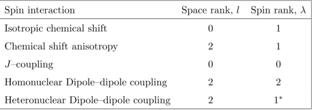
char-acterised by its set of rotational ranks.
Characterisation of an internal Hamiltonian may be done based on the
quantum numbers of the space and spin part. The space rank of a spin
interaction is denoted asland spin rank asλ. An irreducible spherical tensor of rank lhas 2l+ 1 components taking values from m=−l,−l+ 1,· · ·+l. A spatial rotation, such as MAS, induces a mixing of the (2l+ 1) space components. Similarly, the spin rank λ has (2λ+ 1) components taking values µ=−λ,−λ+ 1,· · ·+λ. A spin rotation in the interaction frame of the rf field induces a mixing of the (2λ+ 1) spin components.
Each interaction can therefore be regarded as a superposition of (2l+ 1)×(2λ+ 1) components in the presence of sample rotation (MAS) and resonant rf fields. A particular spin interaction,HΛ may be written as
HΛ= +l
X
m=−l
+λ
X
µ=−λ
HΛ
lmλµ (6)
In the case of exact MAS, the components withl= 2 andm= 0 vanish [4]. Expressions forHΛ may be found in Ref. [31, 32]. Table 1 gives the ranks
for the most important spin interactions and shows that a distinction may
be made among the spin interactions depending on their space and/or spin
ranks. Selective recoupling of these interactions is possible by designing
pulse sequences based on their transformation properties.
6
Symmetry–Based Recoupling Sequences
There are two large classes of pulse sequences based on symmetry principles.
These are known asCNnν and RNnν sequences [4].
Both CNnν and RNnν sequences are characterised by three symmetry numbers,N, nand ν. N is called the step number, whilenand ν are called the spin and space winding numbers. The values of these symmetry numbers
define selection rules which indicate which interactions are decoupled or
6.1 CNν
n Sequences
A CNnν sequence may be constructed by dividing n rotational periods of the sample intoN equal intervals. During each of these intervals a rf pulse sequence is applied which is cyclic, in the sense that it induces a rotation of
the nuclear spins through an integer multiple of 360o. The winding number
ν defines the phase difference between successive rf cycles, which is given by 2πν/N. The sample hence rotates (in space, MAS) through nfull rota-tions and simultaneously experiences a set of rf pulses, the phases of which
advance through ν full rotations. A schematic timing diagram is shown in Fig. 4.
The following selection rule determines whether a spin interaction is
symmetry–allowed to first order, under aCNnν sequence: ¯
H(1)lmλν = 0 ifmn−µλ6=N Z (7)
whereZ denotes any integer [31, 33, 35]. The superscript (1) indicates that the selection rule is valid only to first–order in average Hamiltonian theory
[4].
For illustration, consider a pulse sequence with symmetryC712, i.e.,N = 7, n = 2 and ν = 1. Consider a double–quantum dipole-dipole term with
{l, m, λ, µ}={2,1,2,2}. The expressionmn−µν yields a value 0, which is an integer multiple ofN=7, and hence this term is symmetry-allowed under the pulse sequenceC712. Consider the case of a CSA term with{l, m, λ, µ}=
{2,2,1,1}. The expressionmn−µν yields a value 5 which is not a multiple of N = 7. Hence this CSA interaction is symmetry-forbidden under C712. This calculation may be repeated for all CSA terms with l= 2 and λ= 1. They are all symmetry forbidden underC712.
It is possible to depict the selection rules by a space–spin selection
dia-gram, as shown in Fig. 5. In the case ofC712, all CSA terms are suppressed while two homonuclear DD coupling terms and one isotropic chemical–shift
term are allowed. This sequence therefore recouples homonuclear DD
only dipole-dipole terms with spin quantum number µ = ±2 are allowed, this symmetry generates a CSA–compensated double–quantum recoupling
sequence [4].
6.2 RNν
n Sequences
The general strategy for designing sequences of the form RNnν is as follows [4]:
• Select a pulse sequence elementR that rotates resonant spins by 180o around thex–axis. This element may be a singleπ pulse, a composite
π pulse, or a smoothly modulated rf pulse.
• Derive the pulse sequence element R0 by changing the sign of all rf phases in the elementR.
• Choose the rf field amplitude such that the duration of R and R0, denoted byτR, is equal toτR=nτr/N, whereτr= 2π/ωr is the rotor
period, N is an even integer, and n is any integer. Here ωr is the
angular spinning frequency.
• Form the sequence RNnν by concatenating N/2 phase shifted {R, R0}
pairs as follows:
RNnν = (R)φ(R0)−φ(R)φ(R0)−φ· · ·(R0)−φ
≡ {RφR0−φ}N/2
where the extra phase shifts are specified by φ =πν/N, and ν is an integer.
A schematic of the construction of a RNnν sequence is shown in Fig. 6. The entire sequenceRNnν consists ofN/2 contiguousRR0 pairs spanning
nrotational periods.
The selection rule for RNnν sequences is as follows: ¯
Zλ denotes any integer with the same parity asλ. Ifλis odd, thenZλ is any
odd integer; if λis even, then Zλ is any even integer [32, 34]. This selection
rule is more restrictive than the selection rules for CNν
n sequences [4].
For illustration, consider a pulse sequence with symmetry R185 2.
Con-sider CSA and heteronuclear DD interactions both of which have {l, λ} =
{2,1}. Sincel=2, there are fourm components withm= (−2,−1,+1,+2). Sinceλ=1, there are threeµcomponents withµ= (−1,0,+1). The selection rulemn−µν yields 9 and -9 for the combinations{l, m, λ, µ}={2,2,1,−1}
and{2,−2,1,1}. These terms are both symmetry-allowed since 9 is an odd integer multiple of N2 = 9, and the spin rank λis also odd. Consider now homonuclear DD and isotropic chemical shift terms. For the homonuclear
DD interaction, l = 2 and λ= 2. No combination of {l, m, λ, µ} yields an even integer multiple of N2 = 9 since the spin rankλis even. This means that homonuclear DD interaction are symmetry forbidden for theR1852 sequence. The same holds good for isotropic chemical shift terms wherel= 0 andλ=1. Hence, aR1852 sequence is a suitable candidate for recoupling heteronuclear DD interactions in the presence of homonuclear DD interactions, or for
mea-suring CSA in systems with strong homonuclear DD interactions [36].
Fig. 7 illustrates diagrammatically the selection rule for R185
2. CSA
and heteronuclear DD terms are symmetry–allowed while homonuclear DD
coupling terms and isotropic chemical–shift terms are symmetry–forbidden.
7
Applications of Symmetry-Based Sequences
Solid–state NMR is now used for investigating the molecular structure of
many biologically interesting systems, such as fibrils, fibres, membrane
pro-teins and enzyme propro-teins. Some examples are given in Ref. [37–42]. In the
following section, we concentrate on a few applications of the
symmetry-based sequences to biological systems. A systematic investigation of any
biological system requires the following: sequential assignments via through–
and heteronuclear distance measurements, and torsion angle measurements.
This information can shed light on other mechanistic features like hydrogen
bonds and dynamic effects.
7.1 Assignment Techniques
The route to structure determination of biomolecules is well established in
solution–state NMR. The starting point in spectral analysis is the
assign-ment of the spectral peaks to the respective amino acids. We first discuss
the application of symmetry–based pulse sequences to the assignment of13C
spectra in labelled biomolecules.
7.1.1 Scalar Correlation
Through-bond correlation spectroscopy mediated byJ–couplings is well es-tablished in solution–state NMR [43]. The main ingredient of though-bond
correlation spectroscopy in solid–state NMR is to construct a mixing pulse
sequence that allows only J–couplings to be active while suppressing all other interactions. In terms of the symmetry notation such a sequence
should allow only {m, µ} = {0,0} components, while suppressing all CSA and through-space dipole-dipole coupling terms. One suitable symmetry is
C913 [44]. Many others are known [4].
A schematic of a scalar correlation experiment using a C913 sequence as a mixing element is shown in Fig. 8a. An experimental spectrum of [U–
13C,15N]–bacteriochlorophyll is shown in Fig. 8b [45]. The cross–peaks reveal
13C resonances belonging to sites with a mutualJ–coupling. Similar results
have been obtained on an U–13C labelled cyclic decapeptide antamanide
yielding assignments of most 13C peaks [45].
In this context, we would like to point out that the RFDR pulse sequence
[26–28], which is often proposed to be a dipole-dipole mixing sequence, in
of pure dipole-dipole couplings may be better understood as through-bond
correlation spectra.
7.1.2 Double–Quantum Correlation
The INADEQUATE experiment [49] is widely employed in solution–state
NMR for assigning 13C spectra. Double–quantum correlation spectroscopy
has similar potential in solid–state NMR by allowing only signals passing
through DQ coherences and suppressing signals from isolated spins–12. This
is particularly useful in large 13C labelled biomolecules where the
back-ground signals from naturally–occuring isolated13C nuclei obscure the
spec-trum. As shown earlierC712 is a suitable candidate for DQ correlation spec-troscopy [33]. This symmetry–based sequence recouples homonuclear DQ
couplings. A similar sequence more suitable for high MAS frequencies is
C145
4 [35]. This sequence can be made more efficient by adding supercycles
to reduce resonance offset effects and CSA effects. This sequence is called
SC14 and it recouples DQ dipole–dipole terms with the quantum numbers
{l, m, λ, µ}={2,±1,2,∓2} [35].
A typical pulse scheme employing SC14 for DQ correlation spectroscopy
is shown in Fig. 9a. A 2D DQ spectrum of [U–13C]-L–tyrosine is shown in
Fig. 9b. All the assignments are clearly visible and marked in the spectrum.
DQ filtration effectively eliminates the natural abundance background
from large biomolecules. Fig. 10 shows the 13C spectrum of [11,12-13C2
-retinylidene] bovine rhodopsin, compared with the corresponding double
quantum filtered signal obtained using a R1462 sequence [53]. DQ dipolar recoupling is a key step in many experiments for the determination of
struc-tural information, including internuclear distance and torsion angle
mea-surements (see below).
Many other symmetries suitable for homonuclear DQ recoupling are
7.1.3 Homonuclear Zero–Quantum Recoupling
Homonuclear dipolar recoupling methods allow determination of proximity,
distance and angular information under high–resolution MAS conditions.
Besides the 2Q correlation spectroscopy discussed above, zero–quantum
homonuclear dipolar recoupling may be used for obtaining 2D
longitudi-nal magnetisation exchange spectra which yield a qualitative estimate of
spatial proximity of spin sites, and which can identify resonances
originat-ing in the same spin system, even if the associated spins do not have a direct
mutual coupling [50, 51]. A good ZQ sequence should be practically feasible
at high MAS frequencies, should have minimum dependence on isotropic
and anisotropic chemical shifts, have a low rf field requirement, and the
recoupled DD interaction should be as large as possible.
A good candidate for ZQ homonuclear dipolar recoupling is the
symme-try sequenceR626. This recouples the DD terms with the following quantum numbers{l, m, λ, µ}={2,±1,2,0}and {2,±2,2,0} [52]. A pulse sequence for ZQ homonuclear dipolar recoupling is shown in Fig. 11a. An
exper-imental 2D correlation spectrum of [U–13C]-L–tyrosine acquired with the
sequence in Fig. 11a is shown in Fig. 11b. The large number of cross–
peaks in this spectrum show that the longitudinal magnetisation has been
redistributed over the whole spin system by the zero–quantum recoupling
sequence. This is the solid–state analogue of the TOCSY experiment in
liquids. Ref. [4] lists many other symmetries suitable for homonuclear
zero-quantum recoupling.
7.2 Local Geometry Determination
7.2.1 Heteronuclear Distance Measurements and H-Bond Effects
Heteronuclear distance measurements are very useful for molecular structure
refinements and for investigating protein secondary structure and hydrogen
bondings. Separated local field (SLF) spectroscopy is a classic method for
bond lengths [54, 55]. In this 2D technique the chemical shifts in one
dimen-sion are correlated with the heteronuclear dipolar couplings in the other
di-mension. This high–resolution method normally uses simple multiple–pulse
sequences for decoupling the homonuclear dipolar interactions. Although
originally developed for static samples, it may also be used under MAS [?].
However, the MAS frequency must be slow enough to ensure sufficient
side-band intensity from which both the magnitude and the orientation of the
dipolar tensors may be estimated. In multiply-labelled samples, a high MAS
frequency is required to ensure a good resolution and sensitivity. TC5 [56],
TMREV [57,58] and R-sequences [4,59] have been used at high spinning
fre-quencies, although only the R-sequences have theoretically ideal behaviour
in the first-order theory.
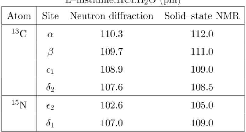
Figure 12a shows a SLF pulse scheme involving aRNnν sequence for het-eronuclear dipolar recoupling. Fig. 12b shows a 13C 2D spectra obtained
on [U-13C]-L-histidine·HCl·H2O at 10.9 kHz spinning frequency [59]. The
splittings in the indirect dimension are proportional to heteronuclear DD
couplings. Distance estimates are obtained by comparing the dipolar
pat-terns with numerically exact two–spin simulations [36]. Table 2 summarizes
the CH bond lengths of L-histidine·HCl·H2O determined by neutron
diffrac-tion [60] and by solid-state NMR. Notice that the NMR bond lengths are
consistently longer than neutron diffraction data due to the librational
mo-tion of the C-H bond in a direcmo-tion orthogonal to the bond [?].
In order to quantify CH or NH bond elongations due to the formation
of H-bonds, an internal calibration can be used. Fig. 12d shows the 15N
2D spectra usingR1852 at 20 kHz spinning speed on uniformly 15N labelled L-histidine·HCl·H2O. Theδ115N–1H bond is found to be about 4 pm longer
than 1 15N–1H bond due to the formation of an intermolecular hydrogen
7.2.2 Homonuclear Distances: Bond Length Determination
The accurate determination of distances between like nuclei is of great
im-portance. For good quality crystals of small molecules, diffraction methods
give very accurate internuclear distances. For large biomolecules, on the
other hand, the typical resolution from diffraction is of the order of 10 pm
to 30 pm, after refinement.
For typical13C–13C bonds in conjugated chains, the single bond distance
is about 150 pm while the double bond distance is about 135 pm. These
correspond to rather different electronic distributions. While single bonds
are typically very flexible, isolated double bonds are quite stiff and the
elec-trons forming the double-bond are expected to be localised between the two
nuclei. Many conjugated systems exhibit intermediate bond orders and the
bonding electrons are much more delocalised. In such cases, high-precision
bond length measurements allow one to answer questions about reaction
mechanism, electronic distribution and molecular motions.
Solid–state NMR can often provide such information. Internuclear
dis-tance measurements can be performed for directly bonded carbon pairs,
using RNnν-sequences for homonuclear DQ dipolar recoupling [61]. The pre-cision is not yet as good for longer distances, although a variety of methods
is available [19, 62].
A pulse sequence for distance measurements between homonuclear spin
pairs is given in Fig. 13a. The DQ-filtered signal intensity depends upon the
duration of the recoupling sequence. This is demonstrated experimentally
in Fig. 13b for the case of [11,12-13C2]-all-E-retinal, a model of which is
shown alongside the spectrum. This series of spectra was acquired using a
fixed reconversion time, τrec, while τexc is incremented. The dipole-dipole
interaction between the labelled nuclei is recoupled and the observed signals
are modulated with a frequency which can be related to the strength of
the dipole-dipole coupling constant and, hence, to the internuclear distance.
to rjk = ...±... pm [61]. The method is sufficiently precise to distinguish
between pure single bonds and double bonds, as well as intermediate cases
in conjugated chains [61].
7.2.3 Torsion angle measurements
The torsion angles of four-atom units is a very important structural
param-eter. In NMR, torsion angles can be estimated by determining the relative
orientation of a pair of anisotropic spin interaction tensors, such as CSA
and DD coupling tensors. Methods have been developed to correlate the
orientations between two CSA tensors [65], two dipolar tensors [66] and one
CSA tensor with a dipolar tensor [63, 64]. The choice of dipolar tensors
is preferred because the dipolar tensor is symmetric and precisely aligned
along the internuclear vector. The orientation of a CSA tensor, on the other
hand, depends on the local molecular structure and needs to be determined
in advance by other methods.
A variety of experiments has been suggested for the determination of
torsion angles [63,64,67,68]. Here, we outline an approach using symmetry–
based pulse sequences leading to a direct measurement of a molecular torsion
angle through the relative orientation of two magnetic spin–spin coupling
tensors. We outline a method demonstrating the measurement of H–C–C–H
torsion angles in 13C2–labelled H–C–C–H moieties. 2Q coherence between
isotopically labelled neighbouring 13C sites are excited (for instance, by a
C712 sequence) and are allowed to evolve in the presence of local fields from the directly–bonded 1H spins. The heteronuclear dipolar fields depend on
the spin states of the protons and also on the geometric relationship of
the two 13C–1H coupling tensors. The experiment monitors the effect of
heteronuclear dipolar interactions which are time–modulated due to MAS
on the 2Q13C coherences generating a modulation of the13C 2Q evolution
that depends on the H–C–C–H torsion angle. This is the solid–state NMR
The pulse sequence for determining the H–C–C–H torsion angle is given
in Fig. 14a [70]. The amplitude of the 2Q signal is measured for a sufficient
number of 2Q t1 intervals. This method has been applied to the
measure-ment of torsion angles in [10,11–13C
2]–rhodopsin [69]. Simulations indicate
that a torsion angle resolution of≈ ±20o can be achieved in the neighbour-hood of thecisconformation and≈ ±10o in the neighbourhood of thetrans
conformation. A clear distinction between cis and trans conformations is
easily achieved [70].
8
Conclusions
In this review an outline of the design of pulse sequences in solid–state
NMR based on the symmetry properties of the spin interactions was given.
Two classes of symmetry-based sequences were highlighted, namely, CNnν
and RNnν . Representative applications of these sequences in various small biomolecular systems were highlighted. It is expected that a systematic
application of these sequences will pave the way for an understanding of
various structural and functional aspects of many biological systems. Work
along these lines is being done in our group and several other research groups.
9
Acknowledgements
We thank Andreas Brinkmann and Ole Johannessen for various discussions
References
[1] Duer, M. J. (Editor) 2002, Solid State NMR Speectroscopy, Prinicples
and Applications, Blackwell Science, UK.
[2] Bennett, A. E., Griffin, R. G., Vega, S. (1994) NMR Basic Principles
and Progress, 33, 1.
[3] Dusold, S., and Sebald, A. 2000, Ann. Rep. NMR Spectrosc., 41, 185.
[4] Levitt, M. H. 2002, Encyc. Nucl. Magn. Reson., 9, 165, Wiley, UK.
[5] Andrew, E. R., Bradbury, A., and Eades, R. G. 1959, Nature, 183,
1802.
[6] Lowe, I. J. 1959, Phys. Rev. Lett., 2, 285.
[7] Bennett, A. E., Rienstra, C. M., Auger, M., Lakshmi, K. V., and Griffin,
R. G. 1998, J. Chem. Phys., 103, 6951.
[8] Detken, A, Hardy, E. H., Ernst, M., and Meier, B. H. 2002, Chem.
Phys. Lett., 141, 78.
[9] Pines, A., Gibby, M. G., and Waugh, J. S. 1973, J. Chem. Phys. 59,
569.
[10] Levitt, M. H. 2001, Spin Dynamics. Basics of Nuclear Magnetic
Reso-nance, Wiley, Chichester, UK.
[11] Hartmann, S. R., and Hahn, E. L. 1962, Phys. Rev., 128, 2042.
[12] Peersen, O. B., Wu, X. L., Kustanovich, I., and Smith, S. O. 1993, J.
Magn. Reson. A104, 334.
[13] Stejskal, E. O., Schaefer, J., and Waugh, J. S. 1977, J. Magn. Reson.,
28, 105.
[14] Mehring, M. 1983, Prinicples of High Resolution NMR in Solids,
[15] Emsley, L., Laws, D. D., and Pines, A. 1999, Proc. Int. Sch. Phys.
“Enrico Fermi”, 129, 45.
[16] Yarim–Agaev, Y., Tutunjian, P. N., and Waugh, J. S. 1982, J. Magn.
Reson., 47, 51.
[17] Raleigh, D. P., Levitt, M. H., and Griffin, R. G. 1988, Chem. Phys.
Lett., 146, 71.
[18] Gan, Z. –H., and Grant, D. M. 1989, Mol. Phys. 67, 1419.
[19] Levitt, M. H., Raleigh, D. P., Creuzet, F., and Griffin, R. G. 1990, J.
Chem. Phys. 90, 6347.
[20] Oas, T. G., Griffin, R. G., and Levitt, M. H. 1988, J. Chem. Phys., 89,
692.
[21] Smith, S. O., Aschheim, K., and Groesbeek, M., 1996, Quarterly Rev.
Biophys., 29, 395.
[22] Gullion, T., and Schaefer, J. 1989, J. Magn. Reson., 81, 196.
[23] Gullion, T., and Schaefer, J. 1989, Adv. Magn. Reson., 13, 57.
[24] Tycko, R., and Dabbagh, G. 1990, Chem. Phys. Lett., 173, 461.
[25] Tycko, R., and Dabbagh, G. 1991, J. Am. Chem. Soc., 113, 9444.
[26] Bennett, A. E., Ok, J. H., Griffin, R. G., and Vega, S. 1992, J. Chem.
Phys., 96, 8624.
[27] Sodickson, D. K., Levitt, M. H., Vega, S., and Griffin, R. G. 1993, J.
Chem. Phys., 98, 6742.
[28] Ishii, Y. 2001, J. Chem. Phys., 114, 8473.
[29] Nielsen, N. C., Bildsøe, H., Jakobsen, H. J., and Levitt, M. H. 1994, J.
[30] Tycko, R., and Smith, S. O. 1993, J. Chem. Phys., 98, 932.
[31] Ed´en, M., and Levitt, M. H. 1999, J. Chem. Phys., 111, 1511.
[32] Brinkmann, M., and Levitt, M. H. 2001, J. Chem. Phys., 115, 357.
[33] Lee, Y. K., Kurur, N. D., Helmle, M., Johannessen, O. G., Nielsen, N.
C., and Levitt, M. H. 1996, Chem. Phys. Lett., 242, 304.
[34] Carravetta, M, Ed´en, M., Zhao, X., Brinkmann, M., and Levitt, M. H.
2000, Chem. Phys. Lett., 321, 205.
[35] Brinkamnn, M., Ed´en, M., and Levitt, M. H. 2000, J. Chem. Phys.,
112, 8539.
[36] Zhao, X, Ed´en, M., and Levitt, M. H. 2001, Chem. Phys. Lett., 342,
353.
[37] Tycko R. 2001, Annu. Rev. Phys. Chem. 52, 575.
[38] van Beek, J. D., Hess, S., Vollrath, F., Meier, and B. H. 2002, Proc.
Natl. Acad. Sci., 2002, 99, 10266.
[39] Asakura, T., Yao, J. M., Yamane, T., Umemura, and K. Ultrich, A. S.
2002, J. Am. Chem. Soc., 124, 8794.
[40] Lindstrom, F., Bokvist, M., Sparrman, T., and Grobner, G. 2002, Phys.
Chem. Chem. Phys., 4, 5524.
[41] Kimura, S., Naito, A., Tuzi, S., and Saito, H. 2002, J. Mol. Struct.,
602, 125.
[42] Ladizhansky, V., Veshtort, M., and Griffin, R. G. 2002, J. Magn. Reson.,
154, 317.
[43] Ernst, R. R., Bodenhausen G., and Wokaun, A. 1987, Principles of
Nuclear Magnetic Resonance in One and Two Dimensions, Clarendon
[44] Heindrichs, A. S. D., Geen, H., Giordani, C., and Titman, J. T. 2001,
Chem. Phys. Lett. 335, 89.
[45] Hardy, E. H., Verel, R, and Meier, B. H. 2001, J. Magn. Reson., 148,
459.
[46] Hediger, S., Meier, B. H., and Ernst, R. R. 1995, Chem. Phys. Lett.,
240, 449
[47] Baldus, M., and Beier, B. H. 1996, J. Magn. Reson., A121, 65.
[48] Lee, M., and Goldburg, W. I. 1965, Phys. Rev. A, 140, 1261.
[49] Bax, A., Freeman, R., and Frenkiel, T. A. 1981, J. Am. Chem. Soc.,
103, 2102.
[50] Boender, G. J., Raap, J., Prytualla, S., Oschkinat, H., and de Groot,
H. J. M. 1995, Chem. Phys. Lett., 237, 502.
[51] McDermott, A., Polenova, T., Bockmann, A., Zilm, K. W., Paulsen, E.
K., Martin, R. W., and Montelione, G. T. 2000, J. Biomol. NMR., 16,
209.
[52] Brinkmann, A., Schmedt auf der G¨unne, J., and Levitt, M. H. 2002, J.
Magn. Reson., 156, 79.
[53] Carravetta, M. unpublished results.
[54] DiVerdi, J. A., Opella, S. 1982, J. Am. Chem. Soc., 104, 1761.
[55] Roberts, J. E., Harbison, G. S., Munowitz, M. G., Herzfeld, J., Griffin,
R. G. (1987) J. Am. Chem. Soc., 109, 4163.
[56] Gross, J. D., Costa, P. R., Griffin, R. G. (1998) J. Chem. Phys. 108,
7286.
[57] Howhy, M., Jaroniec, C. P., Reif, B., Rienstra, C. M., Griffin, R. G.
[58] Reif, B., Hohwy, M., Jaroniec, C. P., Rienstra, C. M.m Griffin, R. G.
(2000) J. Magn. Reson., 145, 132.
[59] Zhao, X., Sudmeier, J. L., Bachovchin, W. W., Levitt, M. H. (2001) J.
Am. Chem Soc. 123, 11097.
[60] Fuess, H., Hohlwien, D., Mason, S. A. 1977, Acta Cryst., B33, 654.
[61] Carravetta, M., Ed´en, M., Johannessen, O. G., Luthman, H.,
Verdegem, P. J. E., Lugtenburg, J., Sebald, A., Levitt, M. H. (2001) J.
Am. Chem. Soc., 123, 10628.
[62] Gregory, D. M., Mitchell, D. J., Stringer, J. A., Kiihne, S., Shiels, J.
C., Callahan, J., Mehta, M. A., Drobny, G. P. 1995, Chem. Phys. Lett.,
246, 654.
[63] Weliky, D. P., Dabbagh, G., Tycko, R. 1993, J. Magn. Reson. A104, 10.
[64] Dabbagh, G., Weliky, D. P., Tycko, R. 1994, Macromolecules, 27, 6183.
[65] Weliky, Tycko, R. 1996, J. Am. Chem. Soc. 118, 8487.
[66] Fujiwara, T., Shimomura, T., Ohigashi, Y., Akutsu, H. 1998, J. Chem.
Phys., 109, 2380.
[67] Schmidt–Rohr, K. 1996, Macromolecules, 29, 3975.
[68] Schmidt–Rohr, K. 1996, J. Am. Chem. Soc., 118, 7601.
[69] Feng, X., Verdegem, P. J. E., Lee, Y. K., Sandstr¨om, D., Ed´en, M.,
Bovee–Geurts, P., de Grip, W. J., Lugtenburg, J., de Groot, H. J. M.,
Levitt, M. H. 1997, J. Am. Chem. Soc. 119, 6853.
[70] Feng, X., Lee, Y. K., Sandstr¨om, D., Ed´en, M., Maisel, H., Sebald, A.,
Levitt, M. H. 1996, Chem. Phys. Lett., 257, 314.
[71] Haeberlen, U. 1976, High resolution NMR in solids:Selective averaging,
[72] Feng, X., Verdegem, P. J. E., Ed´en, M., Sandstr¨om, D., Lee, Y. K.,
Bovee–Geurts, P. H. M., de Grip, W. J., Lugtenburg, J., de Groot, H.
Table 1: Rotational ranks of spin interactions in a diamagnetic solid. Spin interaction Space rank, l Spin rank, λ
Isotropic chemical shift 0 1
Chemical shift anisotropy 2 1
J–coupling 0 0
Homonuclear Dipole–dipole coupling 2 2
Heteronuclear Dipole–dipole coupling 2 1∗
Table 2. Estimated13C–1H and15N–1H bond lengths in
L–histidine.HCl.H2O (pm)
Atom Site Neutron diffraction Solid–state NMR
13C α 110.3 112.0
β 109.7 111.0
1 108.9 109.0
δ2 107.6 108.5 15N
2 102.6 105.0
Figure Captions
Figure 1: (a) A schematic of the MAS technique showing the sample
spinning at an angular frequency ωr about an axis at the magic–angle of
tan−1√2 ≈ 54.7o with respect to the static magnetic field, B0. (b) A
schematic of continuous–wave (CW) decoupling showing the pulse sequence
for observation of rare spins such as13C while the heteronuclear interactions
are suppressed by continuous–wave rf irradiation at the Larmor frequency of
1H. (c) A schematic of the CP pulse sequence in which magnetisation
trans-fer from1H to 13C takes place by matching the rf fields on the 1H and13C
channels according to the Hartmann–Hahn condition. A decoupling field is
applied to the1H channel while observing 13C.
Figure 2: 13C CP-MAS spectra of [13C2,15N]–glycine at different
spin-ning frequencies in a field of 9.4 T. The vertical scales of the spectra are:
(a):(b):(c):(d):(e)=6:4:1:1:1. The MAS frequencies, ωr/2π are indicated
Figure 3: Schematic of a recoupling sequence showing the time–dependence
of the heteronuclear dipolar coupling Hamiltonian, HIS in the interaction
frame of the rf field. (a) The time–dependent evolution ofHIS under MAS.
The integral of the dipolar coupling over a single rotor cycle is zero leading
to an averaging of the dipolar coupling to zero if the spinning speed is
sufficiently high. On the right is shown an internuclear vector between a
carbon nucleus and a nitrogen nucleus traversing a conical path. (b) The
time–dependent evolution of HIS under MAS with two π pulses on the S
spin per rotor cycle. Since eachπ pulse reverses the sign ofHIS the dipolar
coupling is no longer averaged to zero but gets scaled by κ, the scaling factor, depending on the nature of the pulse sequence applied for recoupling.
(Reproduced with permission from Ref. [15]).
Figure 4: Construction of aCNnν sequence. The pulse sequence is set up so thatnsample revolutions are synchronised withN rf cycles. In the simplest version, the rf cycle may be a 2π pulse. The pulses of consecutive cycles increment in steps of 2πν/N.
Figure 5: Spin–space selection (SSS) diagram for the symmetryC712showing the selection of double–quantum dipolar and isotropic chemical shift terms,
and symmetry–forbidden CSA terms. The space part,m, and the spin part,
µ, are split for visual clarity. Only those branches withm≥0 are shown: the branches withm <0 are mirror images. Them= 0 component vanishes in the case of exact MAS. For the symmetryC712, the space branches are spaced vertically by two units corresponding ton= 2. Each of these branches splits into three spin components, with µ= {−1,0,1}, and are spaced vertically by one unit corresponding toν = 1. The barrier on the right has holes at levels 0,±7,±14,· · ·corresponding toN = 7. A spin interaction component is symmetry–allowed if the corresponding branch passes through a hole in
the barrier. If it does not pass through a hole, it symmetry–forbidden and
Figure 6: Construction of a RNν
n sequence. The pulse sequence timing is
set up so that n sample revolutions are synchronised with N rf elements. Each pulse element may be a simple π pulse or a composite π pulse. The phases of the elements alternate between the values ±πν/N.
Figure 7: SSS diagram for the symmetry R1852 showing (a) symmetry– allowed CSA/hetero-DD terms (b) symmetry–forbidden Homo–DD terms
(c) symmetry–forbidden isotropic chemical shift terms. The position of the
holes in the barrier depends on whether the spin rank λis odd or even. In cases (a) and (c), the rank λ= 1 is odd, so the holes in the barrier are at levels ±9,±27. . .. In case (b), the rank λ= 2 is even, so the holes in the barrier are at levels 0,±18,±36· · ·.
Figure 8: (a) Pulse sequence for 2D correlation spectroscopy employing the
mixing sequenceC91
3. The preparation period consists of a CP block
gener-ating 13C magnetisation from 1H. During the mixing period magnetisation
transfer takes place under an isotropic mixing Hamiltonian generated by
the C913 sequence bracketed by two π2 pulses. (b) Part of a scalar correla-tion spectrum of [U–13C, 15N]-bacteriochlorophyll recorded using the pulse
sequence in (a). See Ref. [44] for experimental details. (Reproduced with
Figure 9: (a) Pulse sequence for 2Q correlation spectroscopy using the
sym-metry sequence, C14−45 for 2Q excitation and conversion. I refers to 1H and S refers to 13C. Following ramped CP a π/2 pulse on S converts the transverse magnetisation into S spin longitudinal magnetisation. Theπ/2 pulse is followed by a 2Q–excitation pulse sequence of duration τE which
converts the S–spin longitudinal magnetisation into (±2)–quantum coher-ence. The 2Q coherences are allowed to evolve for a time interval of t1,
and are then reconverted into longitudinalS–spin magnetisation by another
C14−45 block. The longitudinal magnetisation is converted into observable magnetisation by aπ/2 read pulse. (b) Experimental 2D 2Q 13C spectrum of [U–13C]–L–tyrosine. See Ref. [35] for experimental details. (Reproduced
with permission from Ref. [35]).
Figure 10: (a) RAMP–CP 13C spectrum of [11,12-13C2
-retinylidene]-rhodopsin, acquired at 9.4 T and 173 K, at a spinning frequency of 5.5 kHz
(b) Experimental 2D filtered spectrum acquired under the same conditions
using the sequence R146
2 [53, 61]).
Figure 11: (a) Pulse sequence for zero–quantum correlation spectroscopy
using the sequence R626 for the transfer of longitudinal magnetisation be-tween neighbouring sites. (b) Experimental 2D homonuclear13C correlation
spectrum of [U–13C]–L–tyrosine at a spinning frequency of 23.0 kHz, and
a mixing interval of 9.9 ms. (b) Experimental 2D 2Q13C spectrum of [U–
13C]–L–tyrosine. See Ref. [52] for experimental details. (Reproduced with
Figure 12: (a) Pulse sequence for heteronuclear dipolar recoupling where the
Rsequence may be eitherR187
1orR1852. (b) Experimental13C 2D spectrum
of [U-13C6,15N3]-L-histidine·HCl·H2O at 9.4 T and a spinning frequency of
10.9 kHz withR1871 sequence. (c) Sections through the 2D spectrum parallel to theω1 axis. These show the heteronuclear dipolar split patterns for each
of the 13C sites bonded with1H. (d) Experimental 15N 2D spectrum of
[U-13C
6,15N3]-L-histidine·HCl·H2O at 9.4 T and a spinning frequency of 20.0
kHz using R1852. (e) Sections through the 2D spectrum parallel to the ω1
axis. These show the heteronuclear dipolar split patterns for each of the13C
sites bonded with1H. (Reproduced with permission from Ref. [36, 59])
Figure 13: (a) Pulse sequence used for the measurement of distances between
homonuclear spin pairs. The sequence starts with RAMP–CP followed by a
π/2 pulse, to create enhanced longitudinal magnetisation on the spin species
S, in this case13C. This is followed by a recoupling interval of durationτexc
to generate DQ coherences between the labelled spins. This is followed by
an interval of duration τrec during which the DQ coherence is reconverted
back to longitudinal magnetisation and then observed through aπ/2 reading pulse. The whole reconversion block is phase cycled to select DQ coherences
while suppressing all other terms at the end of the excitation block. (b)
A series of double–quantum filtered spectra of [11,12-13C2]-all-E-retinal for
different values ofτexc. The molecular schematic is also shown. (c) Best fit of
Figure 14: (a) Pulse sequence for the measurement of H–C–C–H torsion
an-gles using aC712sequence for 2Q excitation and a MREV–8 [71] for homonu-clear decoupling. (b) Coherence pathway diadram. (c) Signal amplitudes for
[10,11–13C2]–metarhodopsin–I as a function of the 2Q evolution intervalt1.
The filled circles correspond to experimental values. The lines correspond
to best–fit simulations for H–C–C–H torsion angles of|φ|= 140o,160o,170o,
and 180o. The dotted lines indicated that the 68.3% confidence limits on the
a
b
c
Figure 7
Homo-DD
CSA, Hetero-DD
a
b
a
b
300
250
200
150
100
50
0
-50
ppm
Figure 10
a
a
b
a
b
d
c
e
exc /ms
0
0.5
1
1.5
2
t
Figure 13
a
b
c
/