ORIGINAL ARTICLE
Selective element fission approach for fast FEM simulation
of incremental sheet forming based on dual-mesh system
M. H. Zhang&B. Lu&J. Chen&H. Long&H. Ou
Received: 11 August 2014 / Accepted: 15 December 2014 / Published online: 28 December 2014
#Springer-Verlag London 2014
Abstract Incremental sheet forming (ISF) is a highly versa-tile and flexible process for producing low batches of sheet metal parts. Although finite element (FE) method is a key approach in the study of material deformation in metal forming processes, the application of FE in ISF process is still limited. This is due to the enormous simulation time required for ISF processes. Focusing on this problem, this paper pre-sents a new selective element fission (SEF) approach for simulation of ISF process based on LS-DYNA. In the ap-proach, the computational efficiency is improved by reducing the unnecessary calculations of elements outside the localized deformation zone in the ISF process. The introduction of a background mesh for simulation data storage and a separate simulation mesh with varied mesh density for simulation ensures both the efficiency of computation and accuracy of results. To verify the proposed SEF method, two ISF case problems including a hyperbolic cone part and a pyramid part are studied by comparing to the conventional FE approach and the H-adaptive approach in terms of the CPU time, the forming load, the final part profile, and thickness distribution. The influence of two key factors: element size ratio and toolpath segment length is also studied. The results suggested that the developed SEF approach can save the CPU time by up to 74 % with satisfactory accuracy as compared to
conventional FE method, which demonstrates both the effec-tiveness and robustness of the developed SEF approach.
Keywords Incremental sheet forming . Finite element . Dual-mesh . Fast Simulation
1 Introduction
Incremental sheet forming (ISF) is a flexible sheet forming method, which is commonly used for rapid prototyping of sheet metal parts in small batch manufacturing and for cus-tomized products. During the ISF process, a ball-nose forming tool is driven to move along a pre-defined toolpath according to the part design. Along the tool movement, the sheet is gradually deformed to the designed shape without the use of a forming die. During the ISF process, localized deformation of sheet occurs around the area where the tool is in contact with the blank. Due to the incremental deformation nature, ISF process has obvious advantages over conventional forming processes including greater formability, reduced forming load and lower cost of tooling and forming equipment [1]. These advantages have attracted increased attention in the metal forming research community, and this process was considered to have the potential to revolutionize sheet metal forming industry [2]. In recent years, progress has been made in many aspects of ISF technology, including in-depth under-standing in deformation mechanism [3], development of new toolpath generation strategies [4], improved the geometric accuracy [5], new method for thickness prediction [6], and new material processing methods [7]. These advances have helped to make the ISF technology closer for practical appli-cations in different industrial sectors.
M. H. Zhang
:
B. Lu (*):
J. ChenDepartment of Plasticity Technology, Shanghai Jiao Tong University, 1954 Huashan Road, Shanghai 200030, People’s Republic of China e-mail: [email protected]
B. Lu
:
H. LongDepartment of Mechanical Engineering, University of Sheffield, Sheffield S1 3JD, UK
H. Ou
Department of Mechanical, Materials and Manufacturing
In the study of the metal forming process, finite element (FE) method is a key approach in understanding the material deformation of complex processes [8], forming load using different tool paths [9], effects of process uncertainty [10], and dimensional accuracy of forming parts [11]. This is also true for using FE method to simulate conventional sheet metal forming and ISF processes. Concerning the ISF simulation research, Qin et al. [12] presented a numerical investigation on the influence of forming process parameters by modeling the forming process. Eyckens et al. [13] applied finite element method using sub-modeling technique to model the small plastic zone in the incremental forming process with an adequate fine mesh at a computationally accept-able cost. Ayed et al. [14] proposed “simplified analysis modeling” for numerical simulation of incremental sheet forming process. By considering the constitutive strains/ stresses equations and the tool-sheet contact conditions, this model was developed by using shell element with satisfactory results. Henrard et al. [15] studied the in-fluence of material law, FE code, and yield criterion on the accuracy of ISF FE simulation especially in predicting the tool force. These existing works indicate a good potential of using FE approach to analyze the ISF process.
Although FE is an effective mean in ISF research, it also has some considerable limitations for ISF processes as com-pared to other metal forming processes, such as forging and stamping. Excessive simulation time required for ISF process-es is a significant limitation. For example, Bambach et al. [16] reported that 73 CPU hours was required to implement an FE approach to simulate a simple case of forming a cone part. In a similar case, Henrard et al. [17] also pointed out that the simulation of the whole cone was time-consuming even with a very coarse mesh. Two key reasons of the long computing time can be considered as follows [18]: (i) The sheet blank is deformed by tool along a sequence of small increments, which cause hundreds of thousands of increments to be calculated when toolpath is long; (ii) As the contact area between tool and sheet are very small, very fine mesh is required in the contact area to ensure accurate contact and deformations calculation, which requires a large number of elements to be in-volved in the simulation. Due to the expensive compu-tation time according to the above factors, the applica-tion of FE simulaapplica-tion in ISF process is still limited.
Concerning the reduction of computational scale, many efforts have been made. Muresan et al. [19] suggested a decoupling method to study the deformation of localized area. Sebastiani et al. [20] presented a decoupling algorithm to decrease the computing time in ISF simulation. This algorithm focuses on separating the FE model into an elastic zone and an elastic–plastic deformation zone. During the simulation, time-consuming iterations focus on the plastic zone and only a few
key elements are involved. Hadoush et al. [18] proposed a direct sub-structuring method to reduce the computation time. In their work, the assumption was made that plastic deforma-tion zone exists only in local contact area. In this way, the substructures can also be divided into two categories: the plastic nonlinear substructures and the elastic pseudo-linear substructures. Bambach et al. [21] developed a method that introduces a fine-size mesh template which moves along the forming tool instead of adaptive remeshing method to speed up explicit FE simulations. Using this approach, a reduction of up to 80 % in CPU time can be achieved under specific conditions of the simulation cases.
Another approach for reducing the computational time is based on the simplification of contact model. Robert et al. [22] presented a simplified model for the tool-sheet contact condi-tions for SPIF process simulation. In their approach, large incremental steps can be used, and approximately 65 % of CPU time can be saved. Brunssen et al. [23] introduced a primal-dual active set formulation for material involving elas-tic–plastic behaviors. Comparing to the conventional penalty function contact algorithm, primal-dual active method allows for less calculus problem, and possible deterioration of stiff-ness matrix in penalty function method can be avoided. Henrard et al. [24] develop a new model dealing with the tool-sheet contact. This method enables moving contact modeling anywhere on the element surface without the use of penalty method. This method could save considerable simulation time for the ISF process. In spite of the above efforts made, computing time for FE simulation of ISF pro-cesses is still considerably long as the time step restricts the calculation efficiency due to the continuous changing of con-tact conditions [25].
2 Methodology
In the conventional ISF simulation process, elements with smaller size have to be employed as the area of contact between tool and sheet is small. These small-sized elements require a large number of elements and significantly increase the simulation time. To overcome this problem, commercial software such as LS-DYNA has developed strategies such as H-adaptive mesh, in which the mesh density increases gradu-ally at the critical area of tool-sheet contact [26]. However, in this H-adaptive mesh approach, the calculation becomes slower with the increase of element number due to movement of contact zone: the mesh density at the previous contact zone cannot be reduced when the contact area is moved forward. The accumulation of high-density mesh increases the intensity of computation. However, if the mesh density at the previous contact zone was reduced, which requires the replacement of the previous smaller elements by larger-sized elements and the accuracy of previous calculation will be lost. To overcome this
problem, a new strategy is proposed by employing a pre-defined adaptive mesh strategy and an approach of data stor-age on a denser background mesh.
2.1 General description of the selective element fission approach
During the incremental sheet forming process, plastic defor-mation takes place locally at limited area [27]. This area normally covers the tool-sheet contact region and its vicinity. In the simulation process, the use of small elements that are far away from those areas would not affect on the computation accuracy; instead, it significantly reduce the computation ef-ficiency. To overcome this problem, different mesh densities may be assigned to different regions: in the deformation zone, finer mesh may be employed to increase the computational accuracy; in the non-deformation zone, coarser mesh may be used to improve the computational efficiency.
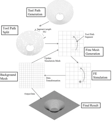
[image:3.595.182.548.316.716.2]Due to the localized deformation in ISF processes, the deformation zone always changes with the tool movement. However, the accumulated total deformation zones for ISF process cover most of the sheet area. If the denser mesh is assigned to the whole deformation area, it would generate large number of elements. Instead of simulating the whole ISF toolpath at a time, the toolpath is divided into a number of segments and the FE simulation is implemented for each toolpath segment in sequence. In this way, denser mesh is only required for a particularly small deformation area in that toolpath segment other than the whole area so the number of elements can be reduced.
To facilitate the proposed strategy for ISF simulation, the ISF toolpath is split into a number of segments, and each toolpath segment will be simulated in sequence. For the simulation of each toolpath segment, the coarser mesh is employed and some of the elements in the coarser mesh are divided into denser meshes if it is established that the tool
passes through a specific toolpath segment. With this varied mesh density, the element number can be reduced comparing to a full denser mesh. After each FE simulation, the result data are transferred into a fine background mesh for storage. Concerning the simulation of another segment, based on the updated geometrical shape and state variables from back-ground mesh, new simulation mesh can be generated and FE simulations can be carried on segment by segment until finish. Figure1described this simulation principle of the proposed SEF approach. The key steps of this SEF approach include (1) toolpath division and simulation planning, (2) selective ele-ment fission, (3) data transaction and interpolation, and (4) generation of new mesh. It is noted that the number of element required in the actual simulation mainly depends on the length of a toolpath segment (or the number of segment division) as well as the size ratio. This size ratio (SR) may be defined as the area of an element before fission comparing to the area of element after fission while the segment number (SN) sug-gested the amount of segments or in other words the number of calculation steps. Thus the element SR and the SN are the key parameters that affect the simulation accuracy and efficiency.
2.2 Toolpath division and simulation planning
Concerning the toolpath generation in the ISF process, the designed part may be sliced in the vertical direction thus a series of contours can be obtained. Based on these contours, spiral toolpath may be generated by interpolating the contours Fig. 2 Element fission (size ratio=4)
[image:4.595.54.265.47.157.2] [image:4.595.231.544.430.712.2]or these contours may be directly employed as layered toolpath. Other types of toolpath may also be employed for ISF process, such as the feature-based toolpaths generated from the equal-potential lines of the designed part or the Zig-Zag type toolpaths [4].
No matter what specific toolpaths are used, these paths are generally formed by a series of discrete points on the trajectory of tool movement. In this work, the ISF toolpath was divided into a series to toolpath segments with equal length. Each segment is simulated in the order to form an integrated ISF simulation. In this way, the computational efficiency can be improved.
Concerning the toolpath division, if there are too many segments, more data transformation operations between the simulation mesh and the background mesh for data storage are needed. The large number of data transformation operations may potentially reduce the simulation accuracy due to the loss of data accuracy in the interpolation process. On the other hand, if the toolpath segment is too long, the potential defor-mation area is increased which requires a finer mesh with a larger number of elements. Because of this, a proper segment length plays a key role in balancing the computation efficien-cy and simulation accuraefficien-cy. With a given segment number SN, the length of toolpath segmentLScan be determined by:
LS¼ L
SN ð1Þ
In the toolpath division, as the generated toolpath is repre-sented by a series of points, the division of toolpath segment can be obtained by:
LS≈
X
kþn−1
i¼k
Pi−Piþ1
j j ð2Þ
wherekis the start point number of a toolpath segment whilen
is the number of points in a toolpath segment. In practice, with a given target toolpath segment lengthLSand a starting point k, the number of pointsnthat involves in this toolpath segment can be calculated by summing up the length of toolpath points
until the accumulated length is approximately equal to the target lengthLS.
2.3 Selective element fission algorithm
As mentioned in the previous section, the deformation of sheet metal occurs in a localized tool-sheet contact region. With properly defined toolpath segment, the potential deformation area during the simulation process can be predicted. In this way, fine mesh can be assigned to the potential deformation area while coarser mesh can be assigned to the other area.
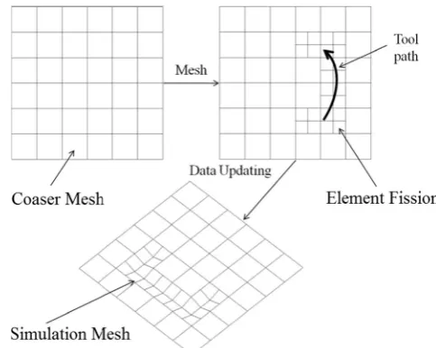
In ISF simulation, structured mesh with shell elements is usually employed. For an initial large shell element with square shape, this element can be divided into smaller square-shape elements by equally splitting the element edge into two or more edges and adding new nodes for the newly generated elements. Figure 2 shows the fission of coarser element into smaller element. It is worthwhile to point out that the element fission method described above would result to an incompatibility at the element edge with different ele-ment sizes. The middle node on a neighboring edge shared by elements with different sizes is calculated by interpolating from the two vertex nodes on the neighboring edge [28]. In Fig. 4 Data transformation from
simulation mesh to background mesh
[image:5.595.232.545.52.183.2] [image:5.595.300.542.505.698.2]this work, this calculation is managed by the LS-DYNA during computation, which ensures the mesh deformation compatibility [26]. Although the use of unstructured mesh could also produce FE mesh with different density, this kind of mesh may cause complex data transformation operation at later stage. Thus, structured mesh seems a better choice for the SEF solution.
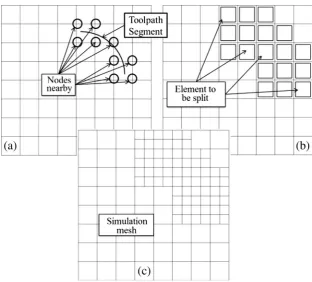
Another issue in the element fission method is to determine which elements are needed to be split. In this work, this is achieved by looking for any elements that are close to the toolpath segment. As presented in Eq.3, for any pointPjon the toolpath, if the distancedN-Pof an element nodeNito the point is within a critical distanced0, this element is considered to be in deformation affected zone and is thus be split.
dNP¼ jNi−Pjj<d0 ð3Þ
The critical distanced0directly determine the number of elements to be split and affect the simulation efficiency. An
appropriate value of d0would enhance the simulation effi-ciency and at the same time maintain satisfied simulation accuracy. In the incremental forming process, the critical plastic deformation zone is limited to the tool-sheet contact and the surrounding area [27]. The value ofd0has to be large enough to include this area so the plastic zone can be covered by the refined mesh in the simulation. In this study,d0is twice the radius of the forming tool. Using Eq.3, all the nodes near the toolpath can be found and the elements that include these nodes are identified and divided into smaller elements. In this way, meshes with different density can be generated for a particular toolpath segment. This process is illustrated in Fig. 3.
2.4 Data transformation and interpolation
To store the simulation data, a background mesh is employed in the approach. To avoid the loss of accuracy during data transformation, the element size of background mesh is de-fined as the same size of the smaller element in the simulation mesh. In doing so, the nodes on the background mesh corre-spond to those on the simulation mesh. The nodal value such
start
Generate background mesh and initial front mesh
Import tool path and divide it to N segments according to a constant length
Remesh the frontmesh referred to the ithtool path segment and
corresponding data of backnode
Submit the calculation file and run
Import the result data to backmesh model
i < N
Output the background data
i=0
i=i+1
Re-write the data of front mesh referred to the stored data of backmesh and generate
the new calculate file
Yes
No
End
Fig. 6 Framework of the developed program
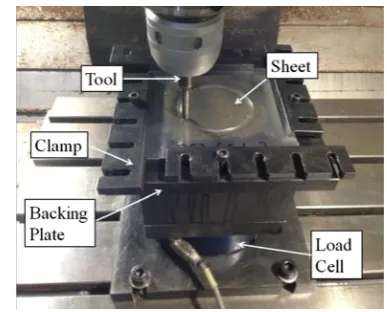
Fig. 7 Experimental setup
[image:6.595.325.519.51.207.2] [image:6.595.94.247.299.702.2] [image:6.595.306.542.536.702.2]as updated coordinates and thickness can be directly assigned to the corresponding nodes on the background mesh. Similar-ly, elemental values such as stress and strain components can also be assigned to the corresponding element in the back-ground mesh as well. For those nodes and elements that do not have direct correspondences due to the different element size between the background and simulation meshes, data interpolation method are employed by using the shape function approach:
Xj¼
X4
i¼1
NiXi ð4Þ
whereNirepresents the shape function of nodeiandXiare the state variables to be transformed. In this way, after the com-pletion of FE simulation for each toolpath segment, the back-ground mesh is updated according to the newly calculated results from simulation mesh as shown in Fig.4.
2.5 Generation of new mesh
Before simulation of each toolpath segment, a new simulation mesh has to be generated according to the current state of
background mesh as well as the toolpath to be simulated. Based on the geometrical shape of present background mesh, new mesh is formed and finer mesh is generated along the toolpath according to the SEF approach proposed in Section 2.3. After the formation of meshes with different density, state variable results are transferred from the back-ground mesh to the newly generated simulation mesh. Similar to the data transformation technique described in Section2.4, if the elements are kept the same, the state variable results are directly assigned to the corresponding elements. If the element in the simulation mesh is larger than the corresponding ele-ment in the background mesh, the average values is taken from the corresponding background elements as presented in Eq.4. In this way, a new simulation mesh can be generated as shown in Fig.5.
Xi¼
Xn
j¼1
Xj
!
=n ð5Þ
[image:7.595.53.553.72.121.2]whereXiare the state variables to be transformed andnis the number of elements in the background mesh which corre-spond to a larger element in the simulation mesh.
Table 1 Material properties of AA5052 calibrated from tensile tests
Yield stressσS(MPa) Young’s modulus
E (GPa)
Tensile strength σb(MPa)
Poisson’s ratio Strength coefficient K Strain hardening index n
Elongationδ(%)
125.7 68.9 258 0.33 406.25 0.2487 19.2
(a) Hypercone Shape
(b) SEF simulation result
(c) Formed Part
[image:7.595.233.549.445.711.2]2.6 Software development
In this work, the implementation of SEF approach is achieved via an in-house developed C# program and the commercial software LS-DYNA. The framework of this program is illus-trated in Fig. 6. As shown in the figure, for any given toolpaths, they are divided into several segments according to a target segment length. For each toolpath segment, ISF FE simulation is implemented in sequence: for a given toolpath, elements of a coarse mesh are split into smaller ones according to the position of the toolpath and ISF simulation is carried out on the refined mesh. After that, the simulated result data including the geometrical information, stress, and strain re-sults are updated corresponding to the background mesh. Based on the stored data in the background mesh and new toolpath information, a new FE input file can be generated and submitted to LS-DYNA solver for simulation. The newly simulated results of the background mesh are updated again. Therefore, the whole toolpath can be simulated on a segment basis.
3 Case studies
In order to evaluate the accuracy and efficiency of the developed approach for ISF simulation, two case study problems including a hyperbolic cone and a pyramid are performed for verification purposes. In each case, the FE simulation results are compared by using conven-tional FE and the H-adaptive method [26] within LS-DYNA as well as the developed SEF approach. The computing time is also measured and compared so the efficiency of the developed approach can be evaluated.
3.1 Experimental setup
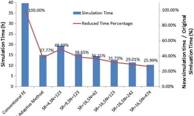
[image:8.595.231.545.54.242.2]The experiments of the two cases were performed on a 3-axial CNC machine as show in Fig.7. In the ISF process, a ball-nose tool with radius of 5 mm was employed. The feed rate of the ISF process for both cases is 1200 mm/min. Spiral toolpath was generated for the ISF process. In case 1 of the hyperbolic cone, a constant step down value (the movement of tool in the vertical direction in each toolpath contour [27]) of 0.5 mm was employed while for case 2 of the pyramid, step down value was defined to be 0.3 mm. Aluminum alloy AA5052 with an initial thickness of 1 mm was used for validation. The stress– strain curve from the uniaxial tensile test for the AA5052 sheet was illustrated in Fig. 8 and the material properties were calibrated as presented in Table1. Using these data, the power law material model in LS-DYNA was employed for simula-tion. The initial size of the sheet is 180×180 mm. In order to reduce the friction between tool and sheet, lubricating grease was employed between the tool and the blank. During the ISF process, a backing plate was placed under the blank sheet to ensure geometric accuracy. Clamps were applied to the edge of the blank. In this way, the blank can be fixed and inaccurate Fig. 10 Comparison of
simulation efficiency
Table 2 Element number under different simulation parameters for case 1
No. Size ratio Segment number Element number
1 Conventional FE 32,400
2 4 62 9000
3 9 62 5400
4 16 474 2385
5 16 242 2775
6 16 123 3405
[image:8.595.306.545.596.712.2]bending of the sheet can be avoided. During ISF experiment, a JR3 multi axis load cell was employed to measure the forming force. After the forming process, a laser displacement sensor was used to measure the cross-section shape of the finished part.
3.2 Case 1: hyperbolic cone
A hyperbolic cone shape, as a commonly used geometry for ISF process, is employed for the process evaluation as shown in Fig.9a. The parts obtained from FE simulation and exper-imental testing is presented in Fig.9b, c, respectively. In order to compare the computational efficiency using different methods, a conventional FE simulation and the newly devel-oped approach are compared. For the newly develdevel-oped SEF approach, the elements with different size ratio from 4 to 16 are employed. In all these cases, the size of initial small element was kept constant as 1 mm while the size of large element varies according to the size ratio. In addition, different toolpath segments are also compared, in which the toolpath segment number are set as 474, 242, 123, and 62. In all the
simulations, the friction coefficient was set to be 0.05 for the contact between tool and sheet. The virtual speed is scaled up by ten times according to the best practice reference, in which the ratio of kinematic energy to total energy can be controlled within a limited value.
In order to evaluate the computational efficiency, the de-veloped fast simulation approach under different element size ratio (SR) and toolpath segment number (SN) are compared with the conventional FE approach as well as the H-adaptive approach. In the H-adaptive simulation model, the refinement level is set to 3 and the original element size is 4 mm, i.e., the same as the model SR=4. As can be seen from Fig. 10, a maximum reduction to 26 % of original simulation time can be achieved from a size ratio of 16 and segment number of 474. As can be seen from the figure, by employing a larger size ratio and larger segment number, the computational effi-ciency can be improved. As given in Table2, it can be found that larger size ratio and larger segment number would reduce the element number in the simulation.
[image:9.595.231.549.55.255.2]Concerning the computational accuracy, forming load in the vertical direction is compared between simulation and Fig. 11 Forming load curve
[image:9.595.231.541.546.711.2]experimental testing as shown in Fig.11. As can be seen from the figure, all the forming loads from simulations are slightly higher than the load measured from experiments. The forming load predicted by the H-adaptive method is always higher than the conventional FE approach. Concerning the effect from the size ratio and segment number, it can be found that the prediction results become slightly worse when the size ratio increases. By increasing the segment number, the forming load becomes lower and closer to the experiment result.
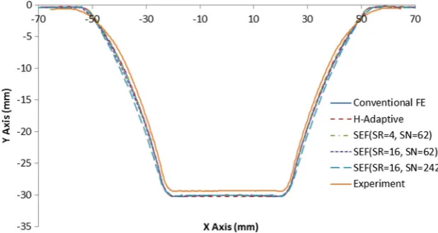
For the geometric accuracy, the final part profiles are compared as shown in Fig. 12. It can be found that the predicted results from all cases of simulation are almost iden-tical. However, a maximum discrepancy of about 0.7 mm can
be observed between the simulated profile and the actual profile. This result suggests a good agreement between nu-merical results and experimental testing. It also indicates that the size ratio and segment number have limited impact on the final part profile.
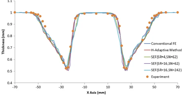
[image:10.595.175.545.56.249.2]The thickness distributions are shown in Fig.13. As can be seen in the figure, the thickness distribution obtained from the conventional FE simulation is quite smooth. However, for other approaches including the H-adaptive approach and the developed SEF approach, although the minimum thickness reduction value is similar, the predicted distribution results are quite bumpy. This bumpy curve may be caused by the inter-polation of the state variable data during the data Fig. 13 Thickness distribution
(a) Pyramid Shape
(b) SEF simulation result
(c) Formed Part
[image:10.595.231.547.439.706.2]transformation process, which may be overcome by introduc-ing improved data interpolation algorithms in the future.
By examining this cone shape case problem, it can be found that simulation time can be reduced to about 26 % of its original time under the size ratio of 16 and the segment number of 474. Concerning the simulation accuracy, satisfac-tory results can be obtained especially for the final part profile and the thickness distribution. In this way, the developed approach may be employed for quick simulation in forming load and thickness reduction evaluation.
3.3 Case 2: pyramid
In this case problem, the dimensions of this pyramid are shown in Fig.14awhile the simulation and the experimentally made parts are illustrated in Fig.14b, c. Similar to the previous case of the hyperbolic cone, both FE simulations and exper-iment were implemented so the efficiency and the accuracy of different simulation methods can be evaluated. In FE simula-tions, the conventional FE approach, H-adaptive approach, as well as the developed SEF approach with varying size ratios and segment numbers were employed. In all these cases, the
size of small element was kept constant as 1 mm while the size of large element varies according to the size ratio.
[image:11.595.231.545.51.247.2]The same as the previous case, conventional FE method example and three remesh method examples are conducted. The H-adaptive method example is set according to the remesh example in which size ratio is 16. Figure 15shows different computing times required under specific conditions. Compared to the previous case, a more than 70 % reduction is also obtained by using the SEF approach. Note that the H-adaptive method example requires less simulation time than the corresponding remesh method example when SL = 200 mm. This discrepancy may be resulted from two sources: (1) compared to the previous case, the forming area is smaller. Element reduction is not as obvious as the previous case. (2) In case 1, the forming step is 0.5 mm while it is 0.3 mm in case 2. In H-adaptive method, once an element is divided, the small elements continue to be part of the model until the end of the simulation. But in the remesh method, small elements are changed back to large elements and in the next step, new small elements are generated at the same position and the results of nodes and element are transferred for a second time Fig. 15 Comparison of
[image:11.595.305.546.543.705.2]simulation efficiency
Table 3 Element number under different simulation parameters for case 2
No. Size ratio Segment number Element number
1 Conventional FE 32,400
2 4 106 8910
3 9 106 5400
4 16 808 2430
5 16 414 2775
6 16 210 3360
7 16 106 4620
[image:11.595.51.289.594.712.2]and hence more time is needed than the adaptive method. When smaller SL value is used, the SEF approach understand-ably is more computationally efficient than the H-adaptive method, as shown in Table3. Compared to the conventional and H-adaptive methods, the same length toolpath requires less time.
Figure16compares the vertical forming load history from the experiment and FE simulation results. As can be seen from the figure, the results from conventional FE approach is quite close to that obtained from ISF experiment. Concerning the H-adaptive method, large fluctuations of the forming load can be observed. For the other cases, the prediction values are more stable. For the developed approach, as the size ratio increases, the forming load becomes less accurate and the error reaches 20 % in the case of size ratio 16. By increasing the segment number, the forming load is slightly lower, similar to the results obtained in case 1. In consideration of the computa-tional efficiency gains achieved from the proposed SEF ap-proach, the prediction results are still satisfactory when a reasonable size ratio is chosen.
To examine the geometrical accuracy, the scanned part profile is compared with the numerical results as shown in Fig.17. Similar to the previous case of the hyperbolic cone part, the predicted results from FE simulations are almost identical. The maximum geometrical deviation of the formed
pyramid is 0.7 mm for the formed pyramid shape ob-tained from the ISF experimental testing and FE simu-lations. This result suggests a satisfactory accuracy of the final part geometry. In addition, it is also noted that the size ratio and segment number has limited effect on the geometrical prediction.
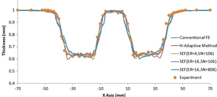
Thickness distribution is another measurement to evaluate the simulation accuracy of this case study. Figure 18 shows the comparison of the thickness distributions of this pyramid part from both numerical and experimental results. As can be seen from the figure, the trends of thickness variation are quite similar. The FE simulation results are quite close to each other, and these results are similar to the actual thickness distribution from experiment. Again, this result suggests satisfactory nu-merical prediction and the effect from size ratio and segment number may be ignored.
By examining this pyramid case problem, it can be found that simulation time can be reduced to about 26 % of its original time at a size ratio of 16 and segment number of 808. Satisfactory prediction can be obtained particularly in geometrical profile and thickness distribution. This case study again proves the robustness of the developed simulation algorithm.
3.4 Discussion
[image:12.595.50.290.50.183.2] [image:12.595.175.545.545.710.2]The developed fast simulation method is based on selective element fission approach, which enables the reduction of the number of elements involved in simulation by representing the localized deformation nature in the ISF process. The case studies of a hyperbolic cone and a pyramid shape suggest considerable simulation time reduction and hence demonstrate its feasibility and robustness of using the developed approach in ISF processes. Comparing to the conventional FE method, the developed approach consumes much less computing time but at the same time maintains satisfactory accuracy in terms Fig. 17 Comparison of final part profile
of part profile and thickness distribution and forming load. Comparing to the other approaches, it is relatively easy to implement as only limited programming on element fission and data transformation is necessary without requiring complex FE formulation and derivation, which has a good potential of widespread applications in ISF pro-cess. In addition, the principal idea developed in this approach including the split of tool paths for individual simulation and the employment of dual-mesh system for d a t a s t o r a g e m a y a l s o b e i n t r o d u c e d t o o t h e r incremental-typed metal forming processes with local-ized deformation such as metal spinning or rolling.
In the proposed method, the size ratio and the number of toolpath segments are two key parameters that affect the computational efficiency. The study of two case problems in this work suggests that large size ratio with increased segment number tend to reduce the simulation time. However, the study on forming load suggested that larger size ratio may produce less accurate results. This inaccuracy may be attrib-uted to the unstable element thickness: the variation of sheet thickness may affect the plastic work and hence the load required for deformation. As can be observed in the two cases, although the trend of thickness distribution is quite similar to that obtained from experiment, the distribu-tion from the fast simuladistribu-tion approach is more uneven than that from conventional FE simulation. In addition, similar observation of fluctuation may be also found for the load prediction. This may indicate the unsmooth contact condition or unsmooth data interpolations values, which may be due to the loss of accuracy during data interpolation process especially for shell thickness and part geometry. Effort is to be made in the future for further improvement of the thickness distribution and load prediction by employing more efficient data interpolation, surface approximation, and thickness calculation methods. In addition, this SEF approach may also be applied in ISF simulation with solid elements for future research.
4 Conclusions
In this study, an FE-based selective element fission (SEF) approach for incremental sheet forming simulation process is presented. By using this method, the FE computing time, geometric profiles and the thickness distribution of form parts, and the vertical forming load are compared to that of the conventional FE method. To validate the proposed method, two common ISF geometrical parts including a hyperbolic cone shape and a pyramid shape are modeled by using the developed SEF approach. The results of two case studies showed a good agreement between the developed SEF
approach and the experimental study. Conclusions of this work may be summarized as follows:
1. By considering the local deformation nature of ISF pro-cess, selective element fission is an efficient approach for FE simulation of incremental sheet forming process. 2. Satisfactory simulation accuracy has been observed
com-paring to existing H-adaptive method, especially for thickness distribution and the final part geometry. 3. The two key parameters of element size ratio and toolpath
segment number, considered in this work, have a notable influence on the computational efficiency as well as pre-diction of forming load; however, they have less effect on the geometric accuracy and thickness distribution.
Acknowledgments The authors are grateful for the financial support provided by the National Key Specific Science & Technology Program from Ministry of Industry and Information Technology of China through Grant 2011ZX04016-051, the EU FP7 Marie Curie International Incom-ing Fellowship Programme (628055 & 913055), the EU Marie Curie Actions—MatProFuture Project (FP7-PEOPLE-2012-IRSES-318968), and the UK Engineering and Physical Science Research Council of UK (EP/L02084X/1).
References
1. Park J, Kim Y (2003) Fundamental studies on the incremental sheet metal forming technique. J Mater Process Technol 140(1–3):447– 453
2. Jeswiet J, Micari F, Hirt G, Bramley A, Duflou J, Allwood J (2005) Asymmetric single point incremental forming of sheet metal. CIRP Ann Manuf Technol 54(2):88–114
3. Lu B, Fang Y, Xu DK, Chen J, Ou H, Moser NH, Cao J (2014) Mechanism investigation of friction-related effects in single point incremental forming using a developed oblique roller-ball tool. Int J Mach Tools Manuf 85:14–29
4. Lu B, Chen J, Ou H, Cao J (2013) Feature-based tool path generation approach for incremental sheet forming process. J Mater Process Technol 213(7):1221–1233
5. Ambrogio G, Filice L (2012) On the use of Back-drawing Incremental Forming (BIF) to improve geometrical accuracy in sheet metal parts. Int J Mater Form 5(4):269–274
6. Cao T, Lu B, Xu D, Zhang H, Chen J, Long H, Cao J (2014) An efficient method for thickness prediction in multi-pass incremental sheet forming. Int J Adv Manuf Technol. doi: 10.1007/s00170-014-6489-9
7. Xu D, Wu W, Malhotra R, Chen J, Lu B, Cao J (2013) Mechanism investigation for the influence of tool rotation and laser surface texturing (LST) on formability in single point incremental forming. Int J Mach Tools Manuf 73:37–46
8. Xia Q, Cheng X, Long H, Ruan F (2012) Finite element analysis and experimental investigation on deformation mechanism of non-axisymmetric tube spinning. Int J Adv Manuf Technol 59(1–4): 263–272
10. Ou H, Wang P, Lu B, Long H (2012) Finite element modelling and optimisation of net-shape metal forming processes with uncertainties. Comput Struct 90–91:13–27
11. Long H (2006) Quantitative evaluation of dimensional errors of formed components in cold backward cup extrusion. J Mater Process Technol 177(1–3):591–595
12. Qin Q, Wu D, Li M, Zang Y (2010) Numerical simulation on the effect of process parameters for incremental sheet forming, Zhuhai, China. Advanced Materials Research. Trans Tech Publications, p 158–161
13. Eyckens P, Van Bael A, Aerens R, Duflou J, Van Houtte P (2008) Small-scale finite element modelling of the plastic deformation zone in the incremental forming process. Int J Mater Form 1(SUPPL 1): 1159–1162
14. Ben Ayed L, Robert C, Delamézière A, Nouari M, Batoz JL (2014) Simplified numerical approach for incremental sheet metal forming process. Eng Struct 62–63:75–86
15. Henrard C, Bouffioux C, Eyckens P, Sol H, Duflou JR, Van Houtte P, Van Bael A, Duchêne L, Habraken AM (2011) Forming forces in single point incremental forming: prediction by finite element simu-lations, validation and sensitivity. Comput Mech 47(5):573–590 16. Bambach M, Hirt G, Ames J (2005) Quantitative validation of FEM
simulations for incremental sheet forming using optical deformation measurement, Erlangen, Germany. Advanced Materials Research. Trans Tech Publications, p 509–516
17. Henrard C, Habraken AM, Szekeres A, Duflou JR, He S, Van Bael A, Van Houtte P (2005) Comparison of FEM simulations for the incre-mental forming process, Erlangen, Germany. Advanced Materials Research. Trans Tech Publications, p 533–540
18. Hadoush A, Boogaard AH (2009) Substructuring in the implicit simulation of single point incremental sheet forming. Int J Mater Form 2(3):181–189
19. Muresan I, Brosius A, Homberg W, Kleiner M (2005) Finite element analysis of incremental sheet metal forming. Proc. ESAFORM, p 105–108
20. Sebastiani G, Brosius A, Tekkaya AE, Homberg W, Kleiner M (2007) Decoupled simulation method for incremental sheet metal forming. AIP Conf Proc 908(1):1501–1506
21. Bambach M (2013) Fast simulation of asymmetric incremental sheet metal forming. AIP Conf Proc 1567(1):844–847
22. Robert C, Ayed LB, Delam E, Zi E, Re A, Dal Santo P, Batoz JL (2009) On a simplified model for the tool and the sheet contact conditions for the SPIF process simulation. Key Eng Mater 410: 373–379
23. Brunssen S, Bambach M, Hirt G, Wohlmuth B (2005) A primal-dual active set strategy for elastoplastic contact problems in the context of metal forming processes. Computational Plasticity: Fundamentals and Applications - Proceedings of the 8th International Conference on Computational Plasticity, COMPLAS VIII, 823–826
24. Henrard C, Bouffioux C, Godinas A, Habraken AM (2005) Development of a Contact Model Adapted to Incremental Forming. Proceedings of the 8th ESAFORM Conference on Material Forming, p 27–29
25. Bambach M, Ames J, Azaouzi M, Campagne L, Hirt G, Batoz JL (2005) Initial experimental and numerical investigations into a class of new strategies for single point incremental sheet forming (SPIF). Proc. Esaform 671–674
26. LS-DYNA Theory Manual (2006) Livermore Software Technology 27. Fang Y, Lu B, Chen J, Xu DK, Ou H (2014) Analytical and
exper-imental investigations on deformation mechanism and fracture be-havior in single point incremental forming. J Mater Process Technol 214(8):1503–1515