Research and Design of UUV Navigation and Control
Integrative Simulation System Based on Component
*
Shengjie Wang, Fengju Kang
Underwater Information and Control State Key Lab, Marine College of Northwestern Polytechnical University, Xi’an, China Email: [email protected]
Received April 21, 2012; revised May 21, 2012; accepted June 5, 2012
ABSTRACT
This paper uses the component-based technology and the object oriented simulation technology to analyze the UUV navigation and control integration simulation system. We divide the system into components based on its structure, and describe every component using active diagram. By using the component-based technology, the system described here is easier to extended and be reused. At last, it realizes the whole UUV integrated navigation simulation course using the system to validate the availability.
Keywords: UUV; Integrative Simulation; Component
1. Introduction
In order to increase the efficiency of the simulation soft-ware development observably, using object oriented tech- nology only during the developing process is not enough; the existent simulation component should be used in si- mulation program construction. The idea of component based technology is to divide the application of the com-plex system into some small and simcom-plex components which can be used in different develop environment. By using the component technology, the system develop-ment can be translated into the developdevelop-ment and integra-tion of the components, and along with the accumulate of the component, the proportion of the development is de-creasing while the proportion of integration is inde-creasing in the develop process of software, therefore, the effi-ciency of the software development is increased greatly but the cost is decreased.
The component based simulation is a very effective form of the simulation software reuse, and lots of resear- chers are worked at the modeling methods of the univer-sal component in different area, for example, Paredis [1] proposed a combined simulation method based on com-ponent. Changjiang Wan [2] put a modeling method of component prototype based on semantics forward to pre-digest the unit simulation environment modeling process. Peng Wang [3] advanced the system construction and the realize method of the CGF according to simulation com-ponent, which can create kinds of force model flexibly and suit different operation platform.
UUV navigation and control system is composed by inertial navigation part, Doppler speed meter, GPS re-ceiver, integrated navigation system and control system etc. For the purpose of reuse the simulation model con-veniently, the model is encapsulated into component ac-cording to its function and demand, then, the UUV navi-gation and control system is constructed to realize the integrative function and provide a digital simulation sup- porting environment for the research of UUV.
2. System Framework
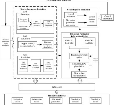
The main function of the navigation and control integra-tive simulation system is to simulate the process that UUV under the function of SINS and take DVL as assis-tant navigation at the settled depth, then after stated time of voyage, climbing to certain depth to modify the data by receiving GPS signal. Figure 1 shows the framework of the system, which include five parts: UUV dynamics and kinematics calculation, multi navigation sensor data simulation, integrated navigation data fusion, control sys- tem simulation, data-base management.
The UUV dynamics and kinematics module receives rudder information to accomplish UUV movement calcu- lation and produce the trail data; the function of the multi navigation sensor data simulation module is to produce each navigation sensor’s data and its navigation calcula-tion; the integrated navigation data fusion module achieves the pretreatment of the navigation data, the estimate and measurement of the public state and the federal filter of the state information; the control system simulation in-cludes the transform of navigation parameter, the control *National key laboratory of underwater information process and control
Dynamics kinematics model calculation IMU simulation component Doppler velocity measurement error Gyroscope simulation Doppler navigation simulation Accelerometer simulation SINS Calculation component GPS Satellite system simulation GPS Receiver simulation GPS Location velocity calculation Control information Data access Control parameter Navigation parameters conversion control system model SINS/DVL local filter Time&measurement update SINS/DVL/GPS globlal filter Time update state estimation
Simulation data base Navigation sensor simulation
The rudder angle instruction
Integrated Navigation Information Fusion SINS Simulation GPS Simulation DVL Simulation
Control system simulation
[image:2.595.100.493.89.450.2]SINS/GPS local filter estimate variance Navigation sensor Information fusion UUV Model parameters Simulation scenario Simulatio result n
Figure 1. Integrative simulation system framework.
system setting and the control model calculation; the si- mulation data-base model composes the data of naviga-tion sensor parameter, informanaviga-tion fusion parameter, UUV model parameter, simulation scenario information and the simulation result.
3. The Design of Navigation and Control
Integrative Simulation System Based on
Component
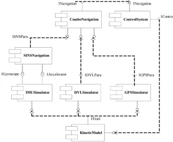
According to its function and construction, the UUV na- vigation and control integrative simulation system can be divided into components showed in Figure 2.
IMU Simulator is the simulation component of the in-ertial measurement unit; DVL Simulator is the simulation component of Doppler speed meter; GPS Simulator is the simulation component of the GPS. they encapsulated re- levant navigation system model. SINS Navigation is the calculation simulation component of the strap-down iner-tial navigation; it can calculate UUV’s navigation infor-mation such as position, velocity, attitude, based on the angle velocity and acceleration information supplied by
IMU. Combo Navigation is the integrated navigation si- mulation component which can realize the information fusion of all the navigation systems and get the integrated navigation information. Control System is the component of the UUV’s control system that in charge of UUV mo- vement control based on the integrated navigation infor-mation provided by integrated navigation component. Kinetic Model is the kinetics and kinematics simulation component of UUV, which is used to calculate its move- ment. The detailed description of the structure and work flow of the IMU simulation component, SINS calculation simulation component, DVL simulation component, GPS simulation component and the integrated navigation si- mulation component is as follows, along with the compo- nent active diagram.
3.1. IMU Simulation Component
char-acter of the inertial device. IMU simulation component is structured by four levels: first, component interface level, including trail information input interface (ITrail), event information interactive interface (IEvent), gyroscope inf- ormation output interface (IGyroscope), accelerator in-formation output interface (IAccelerator), initialization information interface (IInitialization); second, component setting level, including the setting of accelerator error pa-rameter (ParaAcc), gyroscope error papa-rameter (ParaGyro), device scale parameter (ParaScale) and the time parameter (ParaTime); the third one is model calculation level that makes up of math function class (MathFunction), noise produce class (NoiseClass), frame transform class (Fra-meClass), IMU sensor error simulation class (IMUSen-sorErrClass), IMU sensor data create class
(IMUSensor-Class); and the last level is run management level that is composed by thread function (ThreadFunc), timer function (TimerFunc)and simulation operation class (SimRunClass).
The IMU simulation component active diagram is showed in Figure 3.
[image:3.595.127.465.278.555.2]After the start of the simulation component, the first thing is to finish the IMU error model parameter setting, then enter the simulation circle and request time promot-ing, receive UUV trail information, including position, velocity, attitude, angle velocity, acceleration, and trans-form the coordinate for these intrans-formation; simulate the gyroscope and accelerometer measure principle to pro-duce their output information, then, after sending the an- gle velocity and acceleration information out, enter the next simulation periods until the simulation finished.
Figure 2. The simulation component diagram of the navigation and control integrative system.
[image:3.595.58.540.585.718.2]3.2. SINS Calculation Simulation Component
SINS calculation simulation component can complete the calculation process of the strap-down inertial navigation based on the information supplied by gyroscope and ac-celerometer, it can be divided into four levels: first, com- ponent interface level, including SINS navigation infor-mation output interface (ISINSPara), event inforinfor-mation interactive interface (IEvent), gyroscope information input interface (IGyroscope), accelerator information input int- erface (IAccelerator), initialization information input interface (IInitialization), integrated navigation informa-tion input interface (INavigainforma-tion); second, component setting level, including the setting of initial alignment parameter (ParaInitAligment), initial parameter (ParaInit) and the time parameter (ParaTime); the third one is model calculation level that makes up of math function class (MathFunction), frame transform class (FrameClass), the SINS navigation calculation class (ISINSClass); and the last level is run management level that is composed by thread function (ThreadFunc), timer function (Timer-Func)and simulation operation class (SimRunClass).
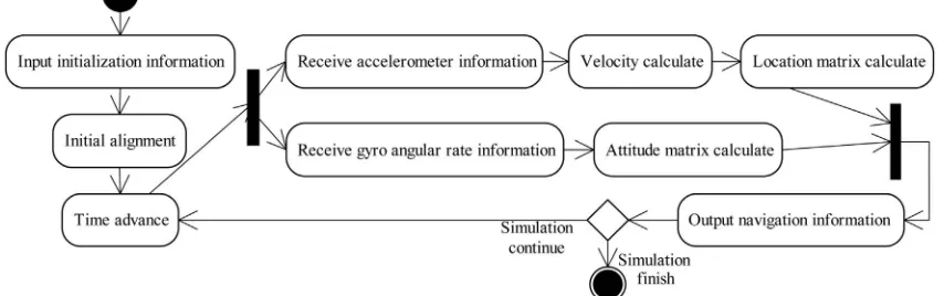
The SINS simulation component active diagram is showed in Figure 4.
At first, SINS component should be initialized and the initial mission contains initial position, initial velocity and the initial alignment of the digital navigation plat-form; then calculates the attitude transformation matrix from body reference frame to navigation reference frame based on the angle velocity measured by gyroscope, ex-tracts the attitude angle of UUV from the attitude trans-formation matrix, meanwhile, calculates the velocity of UUV by using both the attitude transformation matrix and the information from accelerometer, and the latitude and longitude of UUV is given by position matrix calcu-lation; at last, exports the UUV navigation calculation information by the output interface.
3.3. DVL Simulation Component
DVL simulation component can simulate the working
process of Doppler speed meter according to the UUV trail information, and produce the Doppler speed meter information, it contains four levels: first, component in-terface level, including trail information input inin-terface (ITrail), event information interactive interface (IEvent), velocity information output interface (IVelocity), initiali- zation information interface (IInitialization); second, com- ponent setting level, including the setting of initial pa-rameter (ParaInit) and the time papa-rameter (ParaTime); the third one is model calculation level that makes up of math function class (MathFunction), frame transform class (FrameClass), Doppler speed meter simulation class (DVLClass), Doppler error simulation class (DVLSen-sorErrClass); and the last level is run management level that is composed by thread function (ThreadFunc), timer function (TimerFunc) and simulation operation class (SimRunClass).
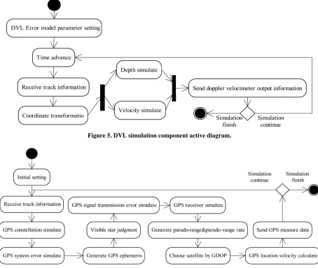
The DVL simulation component active diagram is showed in Figure 5.
After the start of the simulation component, the first thing is to finish the DVL error model parameter setting, then enter the simulation circle and request time promot-ing, receive UUV trail information and transform the co- ordinate; simulate the Doppler speed meter work princi-ple to produce its output information and send the infor-mation to the integrated navigation simulation compo-nent, then, enter the next simulation periods until the si- mulation finished.
3.4. GPS Simulation Component
GPS simulation component can simulate the GPS satel-lites navigation system and provide the ephemeris data; itcan simulate the GPS receiver and choose the satellites, calculate the error, calculate the user’s position and ve-locity according to the navigation message. GPS simula- tion component contains four levels: first, component interface level, including trail information input interface (ITrail), event information interactive interface (IEvent), GPS navigation information output interface
[image:4.595.85.512.583.717.2]gation), initialization information input interface (IInitia- lization); second, component setting level, including the setting of initial parameter (ParaInit), system parameter (ParaSys) and the time parameter (ParaTime); the third one is model calculation level that makes up of math fun- ction class (MathFunction), frame transform class (Fra-meClass), noise produce class (NoiseClass), TLE data manage class (TLEDataClass), SDGP calculation class (SDGPClass), constellation simulation class (GPSSys-temClass), GPS receiver simulation class (GPSReceiv- erClass); and the last level is run management level that is composed by thread function (ThreadFunc), timer fun- ction (TimerFunc) and simulation operation class (Sim-RunClass).
The GPS simulation component active diagram is showed in Figure 6.
At the beginning, GPS simulation component receives the initial information for initial setting, then enters the simulation circle, receives the trail information to simu-late GPS constellation, produces the GPS ephemeris after
GPS error simulation, judges the visible star and adds the transmit error of the GPS signal to simulate the GPS re-ceiver for pseudo-range and pseudo-range rate informa-tion, after uses GDOP for selecting stars, calculates GPS position and velocity information, then, sends the GPS measured data to the integrated navigation simulation component and enters the next simulation periods until the simulation finished.
3.5. Integrated Navigation Simulation Component
[image:5.595.70.524.342.725.2]Integrated navigation simulation component is used to accomplish the fusion of all the navigation systems and give the integrated navigation results. It contains four le- vels: first, component interface level, including SINS na- vigation information input interface (ISINSPara), DVL navigation information input interface (IDVLPara), GPS- navigation information input interface (IGPSPara), inte-grated navigation information output interface (INaviga- tion), event information interactive interface (IEvent),
Figure 5. DVL simulation component active diagram.
initialization information interface (IInitialization); sec-ond, component setting level, including the setting of in- tegrated navigation parameter (ParaInit), system parame-ter (ParaSys) and the time parameparame-ter (ParaTime); the third one is model calculation level that makes up of math function class (MathFunction), frame transform class (FrameClass), SINS/GPS sub-filter class (SINSGPSClass), SINS/DVL sub-filter class (SINSDVLClass), informa-tion assignment class (InfoAssignmentClass), federal fil- ter class (FederalFilterClass); and the last level is run ma- nagement level that is composed by thread function (ThreadFunc), timer function (TimerFunc)and simulation operation class (SimRunClass).
The integrated navigation simulation component active diagram is showed in Figure 7.
Integrated navigation simulation component enters the integrated navigation calculation process after parameter and method setting, receives every navigation system’s
information through input interface according to the out- put frequency of their navigation parameters, then each sub-filter carry out calculation, then federal filter com- pletes fusion calculation of the results from the subfilters by using given information assignment method, and sends the information to the control system component and SINS calculation component.
4. Simulation Result
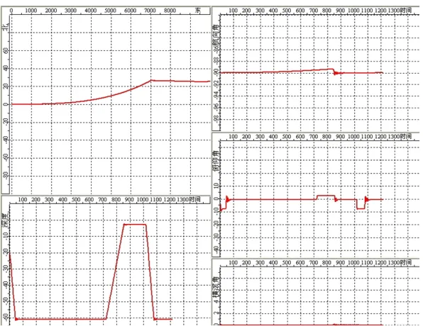
[image:6.595.82.515.317.464.2]Initializing the UUV attitude angles as θ = 0˚, ψ = –90˚, φ= 0˚, and setting the initial position as latitude 20˚0'0'', longitude 120˚0'0'', the initial velocity as 8 m/s, the initial depth as 20 m underwater; and the goal position as lati-tude 20˚0'0'', longilati-tude 120˚30'0'' and depth 60 m under-water. The modify periods is 12 min and it takes 3 min to float near the surface for receiving GPS signal. The whole voyage simulation curve is showed in the Figure 8.
Figure 7. Integrated navigation simulation component active diagram.
[image:6.595.150.448.491.721.2]This figure can be divided into five parts, the top left one is the motion trajectory in east and north plane, the migration of UUV is accumulated after launch, so, after 720 s voyage, it floats to the surface for GPS navigation modification, we can tell the modification of yaw angle from the top right curve. The bottom left curve shows how the depth changed. Firstly, UUV voyages in –60 m, and then floats upward to –2 m to make GPS correction at 720 s. After correction, UUV submerges to –60 m and moves on. The curve in the right-middle shows the change of elevation angle, and the curve in the right- bottom shows the change of roll angles. From Figure 3
we can see the voyage simulation curve is similar with the scenario track.
5. Conclusion
This paper designs and realizes each simulation module of the UUV navigation and control integration simulation system which was analyzed, and describes the structure and working process of each module by activity dia-grams. Through the validation of UUV integrated navi-gation whole process simulation, the simulation modules have well expansibility and reusability. And all of them
can be reused in different simulation programs. It is be- neficial to the development and maintenance of simula-tion program, and provides technical support of the de-velopment of the large comprehensive simulation system in the future.
REFERENCES
[1] C. J. J. Paredis, D. C. Antonio, R. Sinha, et al., “Compos- able Model for Simulation-Based Design,” Engineering with Computer, Vol. 17, No. 2, 2001, pp. 112-128.
doi:10.1007/PL00007197
[2] C. J. Wan, J. R. Tan and A. Y. Liu, “Research on Compo- nent Prototype Modeling Based on Semantics,” China Mechanical Engineering, Vol. 16, No. 16, 2005, pp. 1442- 1446.
[3] P. Wang, B. H. Li, X. D. Chai, et al., “Simulation Com- ponent Based CGF System Architecture and Realization,” Journal of System Simulation, Vol. 19, No. 5, 2007, pp. 1041-1044,