Single Wire Electrical System
Michael Bank
Jerusalem College of Technology, Jerusalem, Israel Email: [email protected]
Received August 18,2012; revised September 22, 2012; accepted October 2, 2012
ABSTRACT
The purpose of this article is to remind of the past and present problems of creating single wire electrical systems. This article presents a new one wire electrical transmission system named B-Line which uses one line only and does not use ground as a second line. The proposed method is to work on all frequencies and on all communication systems includ-ing DC systems. It also proposes to work on the concept of the sinclud-ingle-pole signal source and sinclud-ingle-pole signal load. It illustrates the possibility of cutting the cost of electrical lines and several other advantages in the fields of high fre-quency communication lines and antennas.
Keywords: One-Way System; B-Line; SWER; Grounding; Single-Pole Source; Single-Pole Load; Corona; MB
Antenna
1. Introduction
In most cases, in books, articles or lectures, authors ex-plain the work of a two wire electrical circuit (described below as “A-Line”) as the process of current flowing from the generator to the load by one wire, and then back to the generator by another wire [1]. However, it is known that free access electrons move relatively slowly, and that electrical energy is transmitted at the speed of light. In reality, today’s wired electrical systems use two or more channels (wires) for transmitting energy or in- formation, while in A-Line, both channels have the same information. It is known that active (real) power does not return from the load to the generator. From this point of view, perhaps a second channel in electrical systems is, therefore, not needed. In other words, perhaps a line of an electrical system can be a single wire (or One-Way System).
In prior-art, there were attempts to perform electrical energy transmission by means of one wire. The initial applications of the single-wire electrical energy trans-mission were discovered by Nikola Tesla as outlined in US Patent No. 1119736 [2] and in British Patent No. 8200 [3]. Another single line transmission technique is known as the Goubau line or G-line for short, which is a type of single wire transmission line used at UHF and microwave frequencies [4]. However, a G-line is a type of waveguide rather than a wire in an electrical circuit. In 1993, an experiment was conducted based on the Russian patent application by Stanislav and Konstantin Avra-menko [5-7]. All of the above proposals are based on signal processing methods such as frequency up con-
verting or signal straightening. These processing methods bear a negative influence on information transmission and lead to power loss.
There is also an electricity distribution method using only one conductor, but with the participation of earth. This method is known as the Single Wire Earth Return (SWER). However, the simplification of the energy trans-fer in this system is achieved due to the loss of half the power produced by the source (see part 7 below).
In high-frequency, two-wire long lines are widely used by devices. The length of these lines is either comparable to or greatly exceeds that of the wavelength.
An electrical wire system for the transmission of en-ergy or information can be the only system that uses more than one channel. In wireless systems, energy is transferred over the air by means of electro-magnetic fields. At the point of reception, there exist magnetic and electric fields. The relation between the fields is 120. By knowing one of these fields and the radiation resis-tance (or either current height or effective isotropic aper-ture) of the receiving antenna, we can compute the active power that reaches the receiver. In other words, we are dealing with a one-way system. A fiber optic line or waveguide is the same type of one-way system.
Two-wire long line.
2. Basic Concepts
Following numerous discussions of the proposed sin-gle-wire electrical system, some objections have been voiced, such as: “A single-wire electrical system does not really exist since the current passing through the load must return to the generator.” This section does not pro-vide the theoretical foundations and epro-vidence for a sin-gle-wire line. The main evidence for this is provided through the results of the simulations and modeling de-scribed below. All the laws of nature are the physical explanations in themselves. For example, why is a per-son’s body pushed out of the water, why does an apple fall to the ground, why does the satellite not fall and fly away to infinity? These explanations help the learning process and contribute to the understanding of the proc-ess. This section demonstrates that there are explanations of the process occurring in an electrical circuit, which do not contradict the idea of a single-wire circuit. In this article, the author progresses from the following concepts and ideas.
First concept—Electrical current is not the physical flowing of electrons or of other charges. It is the mathe-matical parameter defined as the ratio of potential dif-ference to the resistance circuit between two nodes. There are other examples where easy to understand and widely used mathematical parameters have no physical equivalent, for example, negative frequencies that result from the spectral transformation. Due to Euler, we know that this is correct, even though there are no negative frequencies in nature. Today, one can read upon the fol-lowing explanation of electrical transfer in a two line system: “Two potentials derived from two terminals of source with opposite phases to two terminals of load with light speed”. Therefore, energy flows in one direction.
Second concept—In electrical equipment, the term “grounding” is used for two different devices: instead of second wire and for zeroing. Using ground instead of one wire is possible for very short distances only; since the resistance of the earth is much larger than the resistance of copper. The resistance of the earth can be from 5 to 5000 ohms per meter. In many electrical systems, ground-ing is used for potential zeroground-ing. An electrical ground system should have an appropriate current-carrying ca-pability to serve as an adequate zero-voltage reference level. In electronic circuit theory, a “ground” is usually idealized as an infinite source or sink for charge, which can absorb an unlimited amount of current without changing its potential. The current flows into the ground and spreads out onto an infinite ground, as is the case with a protective earth. In the case of protective ground-ing, if an accident happens, the current enters ground and
disperses. The main characteristic of the grounding re-sistance is spreading current, i.e., a resistance that the earth (ground) has a current spreading at the site of this current. Land spreading is a ground area that surrounds the grounding electrodes, in which the boundary of the current density is so low that potential, which has virtu-ally no land, depends on the current flowing from the electrodes. That is why outside of this boundary, current can always be equated to zero. In other words, if one point of a scheme is connected to ground, this does not indicate that the energy or the information is transmitted to another point in the scheme, which is also connected to ground. Both points have a potential that equal zero.
Third concept—If one wants to achieve an adequate electrical energy transmitting processing system, it is necessary for the source and load to be able to “see” the same resistances. In addition, the load current must match that of Ohm’s law.
3. The Main Idea, B-Line on Low
Frequencies
We will now look at the main idea for B-Line on low frequencies. To combine two wires in a normal A-Line system, we can change to the opposite signal phase be-yond source by inverter (phase shifter) in one line and to the opposite signal phase in this line when approaching load. Due to invertors using signals in both lines are at the same phase and amplitude, and so we are able to combine them. As the signal approaches the load, we must divide one wire into two lines.
It will be better to explain in detail the main idea of a single-wire electrical system (i.e., B-Line) in comparison
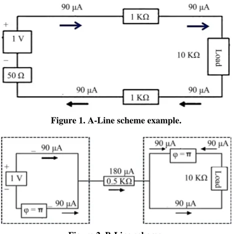
[image:2.595.307.539.493.727.2]Figure 1. A-Line scheme example.
with a conventional electrical system (i.e., A-Line). Fig-ures 1 and 2 schematically illustrate an A-Line circuit
and a B-Line circuit, respectively.
Both circuits include a common power source (e.g., 1 volt generator), a load (e.g., R = 10 KOhm) and the cur-rents are about 90 microamperes (I ≈ 90 μA). At the A-Line circuit, the line’s resistance is about 1 KOhm, and at the B-Line circuit, the resistance of the single-wire transmission line is about 0.5 KOhm as will now be re-viewed in further detail. The equivalent B-Line circuit includes a first phase shifter coupled to one of the poles of the power source and a second phase shifter coupled to one of the poles of the load. An inverter can be as a 10 milliseconds delay line for a signal with a frequency of 50 Hz. At the load side, the single wire splits into two wires (i.e., two lines), and similarly at the generator side, an inverter can be inserted before the load in one of the split wires in order to ensure a normal functionality of the load. As a result, the two wire conventional system (Figure 1) turns into a one-way B-Line system (Figure
2), but the power source 2 and the load 3 will “see” the
conventional two wires system (i.e., A-Line).
On low frequencies, for example, in the case of 50 or 60 Hz frequencies, it is practically impossible to use a delay line as a inverter. Recall that the wire, which cor-responds to a half wave length, has a length equal to 3000 or 2500 km. It is convenient on low frequencies to use other inverters such as transformers with opposite windings as a phase shifter or low pass filter in one line and high pass filter in another line. In digital systems we can implement the Hilbert transform processing. The use of phase shifters and the role of grounding (zeroing) when using a transformer with opposite windings see in [8].
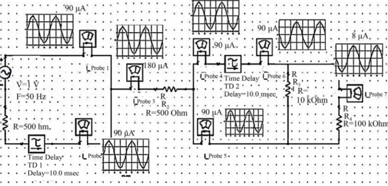
The main idea for the B-Line for low frequencies was supported on ADS simulations programs. A series of simulations with different inverters and various resis-tance lines were carried out. Figures 3 and 4 show the
[image:3.595.101.495.339.528.2]conditions and the simulation results including polarity and magnitude of currents.
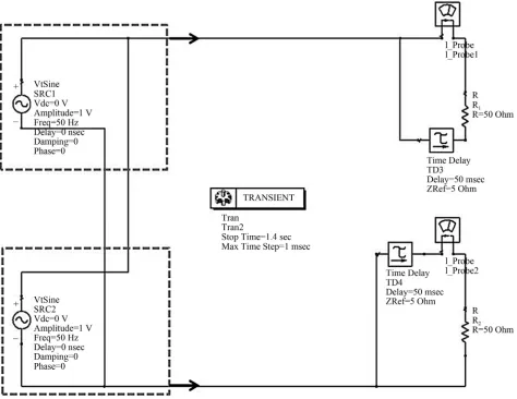
[image:3.595.97.501.551.719.2]Figure 3. Simulation scheme and results of B-Line with delay line as a phase shifter.
One can see on Figure 4 the simulation results of the
B-Line. For example, in the case that the phase shifting device is a transformer with opposite windings, then re-versing one wire current phase by the transformer can reset the current flowing from the winding only. Simply connecting the windings will not work since the current from one winding to another will flow and the trans-former will be incapable to perform its functions. As in other similar cases, zeroing can be done with earth [9].
A number of simulations were prepared with the aim of experimental verification of the proposed solutions. To elaborate, our simulation was constructed from a wooden board where zeroing was done using protective grounding. All voltages and currents in the simulation coincided with the results of the simulation. To eliminate possible doubts about the possible involvement of the land in signal transduction through the neutral wire, a three-phase system was tested in a simulation using a dividing (isolating) transformer at the input. The simula-tion shown in Figure 6 continued to operate normally
even when the receiving part of the simulation is at a distance of about 80 meter and is used as a grounding metal rod.
4. B-Line on High Frequency
We will now illustrate how the idea of the B-line is also correct for high frequency. In high frequencies, one can
implement the CST program. This program allows simu-lating different elements including electrical lines. First we compare a normal long line with a characteristic im-pedance of 300 Ohm with B-Line on a frequency of 1.1 GHz.
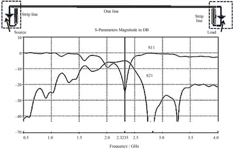
In high frequency, it is possible to produce a inverter as a delay line where its length equals half wave length [10] or a one-port strip line, seeFigure 5.
A simulation of one long wire line was conducted us-ing this strip line, which is normally equivalent to a 300 Ohm long line. The scheme and simulation results in terms of S-parameter (S1 and S2) magnitude (in dB) are shown in the graph in Figure 6.
[image:4.595.317.530.333.397.2]The matching long line has infinite bandwidth. This has an advantage but also a disadvantage. The advantage is that you can pass through a long line of multiple sig-nals with different frequencies. However, in a real sys-tem there is always some noise. Even if the noise is weak, in an infinitely wide band, the noise will still be infinitely
Figure 5. One-port strip line structure.
[image:4.595.67.529.424.718.2]large (this is true, of course, only if the noise is white). Although you can, of course, apply a filter at the input of the receiver, this is often problematic. The filter intro-duces loss and increases the noise factor.
The proposed single-wire system (B-Line) is a selec-tive system. The disadvantage of the B-Line is a need to change the delay line in case of change of frequency. The B-Line is compatible with the source and load, and in this sense no different from the usual long line. It is se-lective, but rather broadband. It has no requirements of symmetry, which is often a problem in the prior-art sys-tems when using long line inside the apparatus, where there can be different influences on each wire.
5. DC B-Line
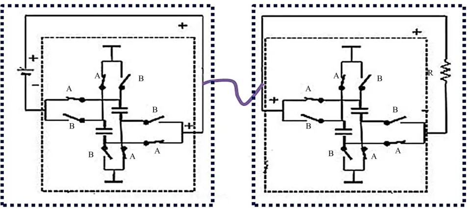
Implementing the inverter (phase shifter) in a DC cir-cuitry requires a different solution then the aforemen-tioned transformers. According to the main idea of the B-Line, it is proposed to use two capacitors and corre-sponding switches to implement the inverter as shown with respect to Figure 7 in the source side and
corre-spondingly at the load side.
Each of the inverters operates as follows: in period A, the first capacitor is charged and the second is discharged. In period B, they switch functions. Charging current is in one direction, but when discharging current, the direction is reversed.
In this example, in line current has one direction, posi-tive or negaposi-tive. In Figure 7, the direction is positive.
The resistance value is usually set. Therefore, the first and second period’s duration can be chosen only accord-ing to the value of the capacitors. For example, such a DC B-Line system can be implemented in an electrical railway system (i.e., tramway). In this case, it is possible
to transmit electrical power only in the wire or only in the rails.
6. Through a Single Wire Electrical System
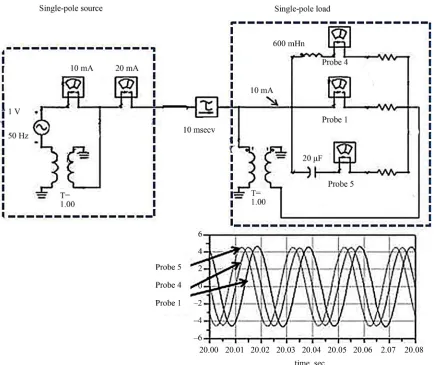
So far we have considered the B-Line as a normal system but one that uses one wire instead of two wires. Maybe it is more correct to speak of the system as one that goes through a single wire electrical system. This system con-sists of a unipolar source, single-trunk line and sin-gle-pole load. Such a system is similar to the fiber optic line. It is possible to implement a single-pole source and single-pole load. Based on the above description, these devices can be implemented as shown in Figures 2, 6and 7 in dotted rectangles.
There are other implementations of the one pole de-vices, for example Faraday’s Unipolar Generator or Ho-mopolar Motor [11].
There are some antennas that are in reality one pole loads, for example, the MB antenna [12].
In some cases, you can get the one pole source without the use of the inverter. For example, if the power station has two identical and synchronous lines in different di-rections then their generators can be used as a two sin-gle-pole source. An example of this type of integration is shown in Figure 8. This example proves once again that
neither the earth nor the inverter is required to build a B-Line system.
It can be shown that for the unipolar system, Ohm’s law remains valid. Table 1 shows the three stages of
[image:5.595.60.539.508.721.2]transition from A-Line to B-Line. The basic A-Line scheme (a) can be transformed into a balance scheme with two lines (b) without changing the current value. By using inverters, we can combine both lines to arrive at the B-Line (c).
Figure 8. Two single-pole (unipolar) sources without inverters.
Table 1.Changing the current in case of the transition from A-Line to B-Line.
Name of scheme Scheme Current in wires
Normal A-Line scheme A 2
g w L
V I
R R R
Balance A-Line scheme A 2
g w L
V I
R R R
B-Line scheme 4 2
2 c
g w L
c A
V I
R R R
I I
that there are two currents (in each of two lines) I/2 on resistance R1. In the SWER scheme on Figure 3 we have
one current on resistance R2.
As in previous simulations we have got double current, because in one wire there are two currents here.
7. One Line Using in Another Known Systems
If we obtain the same power, we arrive at the resis-tance of the wires of the system, as follows:7.1. SWER System
2 2
1 2 2 1
2 2
2 I
R I R R R
The abbreviation SWER is usually defined as “an elec-tricity distribution method using only one conductor with the return path through earth”. However, perhaps this system should be called: “A transmission system over a single wire, where ground is used instead of the second wire and where the distance between the source and the load is large, so that the resistance on the ground between them is much greater than the resistance of the wire”.In fact, the ground in SWER (in generator and in load) leads to zeroing.
So to arrive at the same power generator, we must double the current and double the power (2I and R/2), which corresponds to the results of the simulations. In the case of SWER, the zeroing absorbs half of the power. Therefore, we can say that SWER is a “partial sin-gle-wire line”, since it has lost half of the current
pro-duced by the source. Extensive literature is available on issues related to
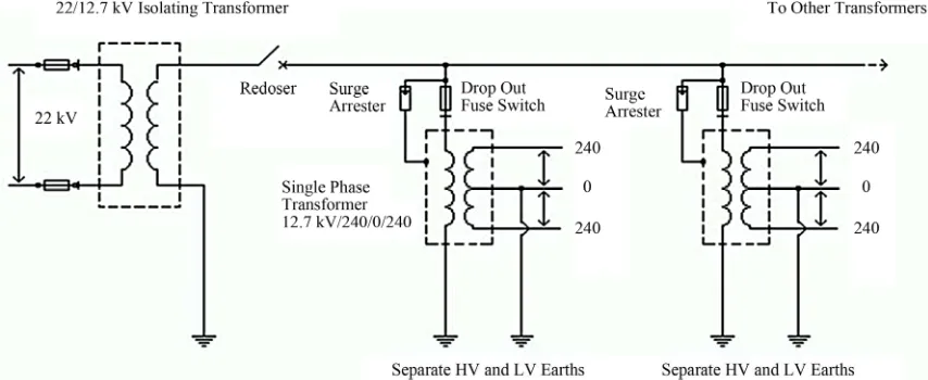
SWER [13]. The most prominent advantages of it are mentioned everywhere. Typically, one can see the SWER scheme as illustrated in Figure 9.
7.2. Three Phase System
The well-known three phase system comprises three combined one-wire systems. If in all three phases there is the same load (balanced scheme), the current in the common wire will be zero. In this case, a common wire is not used. A problem arises if phase loads change un-equally. Without a common wire the current changes even in a phase where the load does not change.
Here we show that between the Isolating Transformer and the load, there are almost no losses. But before look-ing into the isolatlook-ing transformer such a scheme should be doubled to consume energy from the generator. In other words, there is a loss between generator and trans-former. Half of the energy produced by the generator is
absorbed by the earth. The advantages of three phase systems are in using three or four wires instead of six lines for transmitting three signals, since a three phase signal is better for some electrical motors. The disadvantages of a three phase system are having to use three or four wires for transmit-ting one signal for a three phase load and a heightened line voltage that is greater by 1.73 times.
An explanation of this system is made below using simulations via the ADS program (see Figure 10).
Two 0.5 ms delay lines correspond to 150 km long wires. The simulation shows that all three currents equal 25 mA. However, in the SWER scheme, only one current goes to load. We can observe the scheme for the SWER
variant simulation on Figure 11. The electrical system method allows you to build a
single-wire three phase system through a single wire, which allows to connect to a three phase signal using one wire only (see Figure 12).
[image:7.595.83.510.544.719.2]There are 20 mA currents in probes 2 and 3, but in probe 1 the current is 40 mA. We will now explain this result. In a normal scheme (Figure 2), we can assume
Figure 10. The normal two wire scheme.
Figure 11. SWER version of scheme on Figure 2.
In this scheme, the single-wire is split into three wires, in which each of the above mentioned three wires is connected to a different pole of a three phase load via a corresponding phase shifting device. Its purpose is to form a single-wire three phase system, in the following manner:
1) A first phase shifting device is coupled to one of the poles of the three phase load in such a manner that the mentioned first phase shifting device shifts the phase of a first signal propagating through the pole by –120 degrees;
2) A second phase shifting device is coupled to the third pole of the three phase load;
3) A third phase shifting device is coupled to the sec-
ond pole of the three phase load in such a manner that the second phase shifting device shifts the phase of a second signal propagating through the second pole by +120 de-grees.
This scheme does not need an additional wire even in the case of different three load resistances (like on Fig-ure 12).
8. Power Loses and Interference
Figure 12. Three phase B-line scheme and simulation results.
four times smaller. However, there are other factors af-fecting the level of losses. One of these factors is the Corona Effect.
Corona, or Crown, is a self-discharge that occurs in highly non-uniform fields, in which the ionization proc-esses can occur only in a narrow region near the elec-trodes, for example, in the electric field of overhead power lines’ wires.
When two oppositely charged corona wires’ ions of opposite sign move in opposite directions, the radiation level increases [14].
In low field strength, situated in the middle between the wires, there is a partial recombination of the ions. Moreover, if there are two wires that penetrate the Crown area of the opposite polarity, this will increase the field. As a result, the ionization rate increases, while the cur-rent Crown, and, consequently, the energy loss increases. This method is called bipolar corona Crown [14]. Today, considerable attention is paid to the Crown, as it affects the conditions of the environment and leads to energy loss.
9. Conclusions
1) The Single Wire Electrical System for connection between source and load by one line—(method B-Line) was proposed and checked by simulations and experi-ments.
2) The Single Wire Electrical System includes a sin-gle-pole source, one wire and sinsin-gle-pole load.
3) It is possible different types of The Single Wire Electrical System: DC B-Line, LF B-Line, HF B-Line and B-Line three phase system.
4) We can assume that by using the one-way method, we can considerably decrease the electrical lines cost.
5) The B-Line method allows decreasing energy loss in high-voltage electrical transmission lines.
6) A B-Line three phase system has one wire only that provides three voltages for a three phase device.
7) It is possible to achieve a decrease of electrical lines radiation, including Corona effect, on condition that one of the radiation courses in the two lines and three phase systems have a high voltage between lines.
frequency long lines and improving their options, in-cluding easing the requirements for symmetry, good matching and selective properties.
9) The B-Line method allows building antennas with one radiated element (monopole) equivalent to two ele-ment antenna (dipole).
REFERENCES
[1] E. Weber and F. Nebeker, “The Evolution of Electrical Engineering,” IEEE Press, Piscataway, 1994.
[2] “Apparatus for Transmitting Electrical Energy,” Tesla US Patent No. 1119736, 1914.
[3] “Improvements Relating to the Transmission of Electrical Energy,” Tesla US Patent No. 8200, 1906.
[4] G. Goubau, “Surface Waves and Their Application to Transmission Lines,” Journal of Applied Physics, Vol. 21,
No. 11, 1950, pp. 1119-1128. doi:10.1063/1.1699553
[5] C. A. Yost, “Longitudinal Electrodynamic Wave Experi- ments,” Electric Spacecraft Journal, Vol. 12, 1994, pp. 18-
19.
[6] Stanislav and K. Avramenko, “Solid State Space-Energy Generator,” New Energy News, August 1994.
[7] Stanislav and K. Avramenko, “Method and Apparatus for Single Line Electrical Transmission,” The Russian Patent: PCT/ GB93/00960, 1993.
[8] M. Bank, “One-Way Line System for Transmitting En- ergy or Information,” International Journal of Commu- nications, Vol. 6, No. 2, 2012, pp. 55-63.
[9] G. Hunka, “Circuit Grounds and Grounding Practices,” Undergraduate Laboratory, University of Pennsylvania. http://www.ese.upenn.edu/detkin/instruments/misctutorial s/Ground/grd.html
[10] Application Note 123.
http://www.polarinstruments.com/support/cits/AP123.html [11] T. Valone, “The Homopolar Handbook,” Integrity Research
Institute, Beltsville, 1994, p. 45.
[12] M. Bank, M. Haridim, V. Tsingouz and Z. Ibragimov, “Highly Effective Handset Antenna,” International Jour- nal of Communications, Vol. 6, No. 2, 2012, pp. 80-87.
[13] The Electricity Authority of New South Wales, “High Volt- age Earth Return Distribution for Rural Areas,” 4th Edi- tion, EANSW Publication, Sydney, 1978.
[14] E. Mayerhoff, “Corona and Its Effects.”

![1,3 Dibenzyl 1H anthra[1,2 d]imidazole 2,6,11(3H) trione](data:image/gif;base64,R0lGODlhAQABAIAAAP///wAAACH5BAEAAAAALAAAAAABAAEAAAICRAEAOw==)