© 2019, IRJET | Impact Factor value: 7.34 | ISO 9001:2008 Certified Journal
| Page 1633
A RESEARCH ON VIBRATION ANALYSIS & OPTIMIZATION OF HOUSING
FOR ECU IN AUTOMOBILE USING FEA & FFT ANALYZER
Prathamesh Mirajkar
1, Prof. M.L. Thorat
21PG Student, Department of Mechanical Engineering, RMD Sinhgad School of Engineering, Warje, Pune
2Asst. Professor, Department of Mechanical Engineering, RMD Sinhgad School of Engineering, Warje, Pune
---***---Abstract—Electronic Control Unit housings are subjected to various harmonic vibration loads generated by engine at various RPM levels. Encounter of resonant frequencies of housing in specified frequency range can cause damage to PCB enclosed within housing. Vertical vibration/excitation levels are dominant which cause bending moments in PCB and housing. Basic design of housing will be done using CATIA. Finite Element Analysis shall be used to design and optimum housing which will sustain harmonic loads coming from engine vibrations. Modal & Harmonic analysis will be used to investigate mode shape and response of enclosure at specified frequency ranges. Experimental modal analysis will be performed using accelerometer, impact hammer, & FFT analyzer. Comparative analysis will be done on FEA & Experimental results.
Keywords—ECU, FEA, MODAL& HARMONIC ANALYSIS, IMPACT HAMMER TEST, FFT ANALYZER.
1. INTRODUCTION
The electronic control unit (ECU) used in today’s cars and trucks is used to control the engine and other components’ functions. An ECU is a computer with internal pre-programmed and programmable computer chips that is not much different from a home computer or laptop. The vehicle’s engine computer ECU is used to operate the engine by using input sensors and output components to control all engine functions.
The ECU needs inputs from vehicle sensors like the crankshaft sensor and camshaft sensors to compute the information using a program that has been stored in the ECU on a programmable memory chip. The ECU program will use the inputted sensor information to compute the needed output like the amount of fuel injected and when to spark the coil in order to start the engine.
There are different ECUs used for different systems on the vehicle. The different ECUs used can be for the transmission, traction control or ABS, AC, body functions and lighting control, engine, air bags, or any other system a vehicle may have. Some vehicles may incorporate more than one ECU into a single unit called a powertrain control module (PCM). These units can be an advantage by having more modules in one location but may be a disadvantage by adding longer wires to reach the component it operates.
Most never vehicles have started using a communication line between different modules on a vehicle so they can
share information and redundant sensors do not have to be used. For instance, a speed sensor at a wheel detects the wheel speed and will be an input to the anti-lock brake module (ABS) ECU. Instead of sending many wires from the one sensor to other ECUs, the ABS ECU will share the information on the network communication lines to all the ECUs that use the information, like a transmission for its shifting of gears, the speedometer to show the speed of the vehicle, or the suspension system to control the suspension as needed.
The use of sharing input sensors throughout the vehicle using only two data lines between ECUs has cut the amount of wiring used in the vehicles. Sharing information between modules also means they need a common language between them so they can operate as a group. When one computer goes down or does not share information due to an error, then it may affect other modules if they need the sensor input from the failed module.
The engine ECU in most vehicles is connected to the onboard diagnostic connector and will relay all diagnostic information on this line to all the other modules or ECUs. This reduces the amount of wire needed and you do not need to go to each ECU when wanting to test them
2. LITERATURE REVIEW
Wang Lu, Chen Xiao-kai, Zhao Qing-hai“Muti-objective topology optimization of an electric vehicle’s traction
battery enclosure”Science direct Energy Procedia 88
(2016) 874 – 880.
© 2019, IRJET | Impact Factor value: 7.34 | ISO 9001:2008 Certified Journal
| Page 1634
Niteen T. Kakade, Pro.D.G.Gangwani“Design and Optimization of Sheet Metal Enclosure with the Help of
Behaviour Modelling ” IOSR Journal of Mechanical and
Civil Engineering (IOSR-JMCE) e-ISSN: 2278-1684, p-ISSN: 2320-334X PP 39-42.
In this paper, sensor housing which consists of four sheet metal parts and going to take this little assembly and set it up and go through and run through the analysis and while doing that it going to be pointing out some of the changes that have taken place . So the first of these point out before it even go into analysis and that it taken all the options that used to be in the old analysis file and it is incorporated those into the Pro/Engineer preferences editor. So what this lets it do is go ahead and search for all those difficulties. For instance let’s say that it used to know that it used to be able to specify where temporary directories were written during an analysis. So it is going to go ahead and say that it wants to search simulation with the help of software.
Bikesh Kumar and Damodar Reddy “Design optimization of army radar frame(ARF) for thermal an structural
conditions”International journal of mechanical
engineering and robotics research, ISSN 2278 – 0149 www.ijmerr.com Vol. 3, No. 4.
This paper illustrates about Sensitive electronic equipment operating in harsh environment depend upon the vibration protection of the equipment. General methodology that is followed is to optimize the design for vibration for random loads by using damping and stiffness of mounts and is mostly stressed on optimizing the dynamic response of internal components. But the vibration protection of the equipment depends and on the dynamic response of the external structure which is very often neglected. In this project total emphasis is laid on to make a optimal design and improve the design stiffness of the external structure. In the present paper an Army Radar frame has been designed and optimized for vibration control and temperatures using Ansys. Army Radar Frame (ARF) is a structural frame used to mount the communication antennas and the supporting electronic equipment for the system.
Prudhvi Krishna Amburi and K Sreenivas “ Design and optimization of an antenna frame for themal and
structural conditions” ”International journal of
mechanical engineering and robotics research, ISSN 2319-5991 www.ijerst.com Vol. 3, No. 4.
As the power densities of power converters continue to grow, thermal issues are becoming extremely important and vital for the product quality. Excessive temperatures of the critical components, such as Low Band Homodynes (LBH) and High Band Homodynes (HBH), are the dominant cause of equipment failures. Power systems for heavy electronic equipment are usually housed in completely sealed enclosures due to safety reasons. Since the cooling of these systems primarily relies on natural convection, the
effective management of the heat removal from a sealed enclosure poses a major thermal-design challenge. In fact, thermal design through thermal modeling and simulation is becoming an integral part of the design process because it is usually less time consuming and less expensive compared to the experimental cut-and-try approach. In the present paper a Antenna Frame's (AF) antenna mounting frame has been designed and optimized for vibration control and temperatures. Antenna Frame (AF) is a structural frame used to mount the communication antennas and the supporting electronic equipment for the system.
Li Cheng, “Interior sound and vibration control for air
vehicle applications” 23rd Congress on Sound and
Vibration, Athens, Greece.
This paper discuss about Effective interior noise and vibration control inside an acoustic enclosure surrounded by flexible vibrating walls is a typical vibro-acoustic problem, relevant to numerous applications. To tacklethe problem, a comprehensive set of technological knowhow, including the development of efficient and flexible modelling and optimization tools, thorough understanding of the underlying physics as well as the development of effective control means is indispensable. This paper reviews and highlights some of the past and on-going work undertaken by the speaker and his team in this area. Topics include the discussions on the general structural-acoustic coupling, development of efficient simulation, analysis and optimization tools, as well as various passive and active control techniques, all under the context of interior noise and vibration control for air vehicles and space structures.
Titouan Fourmaux, Morvan Ouisse, Scott Cogan, Emeline Sadoulet-Reboul, “Sensitivity analysis and optimization of sheet steel thickness for vibroacoustic behavior of
enclosures” 1st Euro-Mediterranean Conference on
Structural Dynamics and Vibroacoustics (MEDYNA 2013), Jan 2013, France. pp.1 - 4, 2013. <hal-00993447>.
In automotive applications, one of the keys to ensure weight reduction is the optimization of the sheet steel thickness. This paper presents a non-exhaustive list of sensitivity analysis methods (local, global and energy-based) allowing to determine which thicknesses could be reduced. The first results of an adaptive optimization procedure allowing reduction of the thicknesses under design constraints are also illustrated for the modal behaviour of an academic structure representing a simplified cab coupled with an acoustic cavity.
G.S. Aglietti, and C. Schwingshackl “Analysis of Enclosures and Anti Vibration Devices for Electronic Equipment
for Space Applications” School of Engineering Sciences,
© 2019, IRJET | Impact Factor value: 7.34 | ISO 9001:2008 Certified Journal
| Page 1635
Electronic units form a considerable part of the spacecraft bus mass budget, and a significant mass saving could be made by improving their mechanical design. Attention is focussed on the analysis of typical enclosures for electronics, and the anti vibration devices for the Printed Circuit Boards (PCBs) currently used within the enclosures. A crucial step to improve the equipment design is the accurate prediction of the vibration response of the electronics (i.e. populated PCBs), to the vibration environment experienced during launch. FE models of PCBs and Anti-Vibration Frames are presented and compared with the results obtained during random vibration tests.
Literature Summary: From the literature I got idea of
controlling vibrations of Housing of ECU by adding ribs from inner side.
3. PROBLEM STATEMENT
In the present work the aim is to find optimize the housing of ECU solution which should be efficient than the existing model of ECU without affecting the PCB. The optimise housing of ECU of FEM results will be compared with the existing on the basis of vibration and weight. The effect of increasing the vibration on the area of housing will be analysed.
4. OBJECTIVES
1. The objective is to design a housing of electronic control unit (ECU) using CatiaV5 by reverse engineering
2. Carry out the finite element analysis (FEA) on the prepared model using ANSYS.
3. To verify mode shapes generated at different frequencies in ECU and minimize the vertical vibration by adding cross ribs to the ECU.
5. METHODOLOGY
• Step 1: - I started the work of this project with literature survey. I gathered many research papers which are relevant to this topic. After going through these papers, I learnt about optimization of housing for ECU
• Step2: - After that the components which are required for my project will be decided.
• Step 3: - After deciding the components, the 3 D Model and drafting will be done with the help of CATIA software.
• Step 4: - The components will be manufactured and then assembled together.
• Step 5: - The Analysis and optimization of model will be carried out with the help of ANSYS 19 software.
• Step 6: - The Experimental Testing will be carried out on FFT analyzer.
• Step 7: - The comparative analysis will be done between experimental observations and analysis and the result and conclusion will be drawn.
6. DESIGN
Computer-aided design (CAD) is the use of computer
systems (or workstations) to aid in the creation, modification, analysis, or optimization of a design. CAD software is used to increase the productivity of the designer, improve the quality of design, improve communications through documentation, and to create a database for manufacturing.
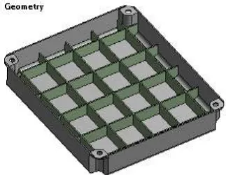
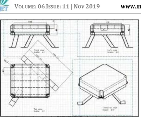
[image:3.595.343.522.396.533.2]Housing for ECU design model have made on Catia software. First I drawn part design and after that made assembly of all parts, making complete model of ECU Housing. Drafting of ECU Housing Model with Stiffeners is drawn in paper.
Fig. 1 CATIA model ECU housing without Stiffener.
[image:3.595.343.505.564.689.2]© 2019, IRJET | Impact Factor value: 7.34 | ISO 9001:2008 Certified Journal
| Page 1636
Fig. 3 Drafting of ECU Housing Model
7. ANALYSIS
It is a numerical technique for finding approximate solutions to boundary value problems for partial differential equations. It is also referred to as finite element analysis (FEA). FEM subdivides a large problem into smaller, simpler, parts, called finite elements. The simple equations that model these finite elements are then assembled into a larger system of equations that models the entire problem. FEM then uses variation methods from the calculus of variations to approximate a solution by minimizing an associated error function.
For model analysis of ECU Housing with and without stiffener. First we are converting Catia file (dot CATPART) into dot STP. After that we are meshing of geometry of ECU Housing model. From meshing we get node and element. After that we Appling boundary condition to model and obtain natural frequency of ECU Housing with and without stiffener.
Material properties of ECU Housing
Aluminum alloy material is used for analysis of ECU housing as the physical ECU is of Aluminum alloy
MESH
[image:4.595.346.529.145.319.2]Higher order tetrahedron elements have been used while meshing to get more accurate results.
Fig. 4 Meshing of ECU Housing without stiffeners
Fig. 5 Meshing of ECU Housing with Stiffeners
7.1 Modal Analysis:
Modal analysis is the study of the dynamic properties of systems in the frequency domain. Examples would include measuring the vibration of a car's body when it is attached to a shaker, or the noise pattern in a room when excited by a loudspeaker.
Modern day experimental modal analysis systems are
composed of 1) sensors such
[image:4.595.353.525.359.531.2]© 2019, IRJET | Impact Factor value: 7.34 | ISO 9001:2008 Certified Journal
| Page 1637
Boundary Condition
After carrying out meshing of ECU the boundary conditions are applied to it. The same boundary condition is applied as that is experienced by the physical ECU.
[image:5.595.55.265.204.341.2]In this analysis, the base faces of stand on which ECU in mounted are fixed and modal analysis is carried out. First 6 modes have extracted. The result plots are added below.
[image:5.595.56.260.392.534.2]Fig. 6 Boundary Condition of ECU Housing model without stiffeners
[image:5.595.358.508.424.536.2]Fig. 7 Boundary Condition of ECU Housing with Stiffeners
Fig. 8 Modal Analysis of ECU Housing without stiffeners
From model analysis we get natural frequencies of first six modes as listed below:
MODE FREQUENCY (Hz)
1 161.59
2 313.83
3 391.2
4 516.44
5 534.31
6 708.76
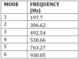
Fig. 9 Modal Analysis of ECU Housing with Stiffeners
From model analysis we get natural frequencies of first six modes
MODE FREQUENCY
(Hz)
1 197.7
2 306.62
3 492.54
4 530.66
5 763.27
6 930.05
7.2 Harmonic Analysis:
Harmonic analysis is a branch of mathematics concerned with the representation of functions or signals as the superposition of basic waves, and the study of and generalization of the notions of Fourier series and Fourier transforms (i.e. an extended form of Fourier analysis). In the past two centuries, it has become a vast subject with applications in areas as diverse as number theory, representation theory, signal processing, quantum mechanics, tidal analysis and neuroscience.
[image:5.595.61.261.570.707.2]© 2019, IRJET | Impact Factor value: 7.34 | ISO 9001:2008 Certified Journal
| Page 1638
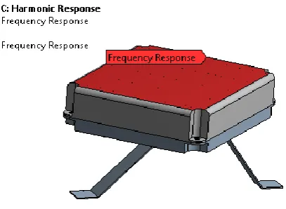
[image:6.595.318.547.109.287.2]In this harmonic analysis of ECU, in addition to fixity, vertical acceleration is applied as external excitation. And results of both models are compared.
[image:6.595.48.265.138.267.2] [image:6.595.37.293.312.424.2]Fig. 10 Harmonic Analysis of ECU Housing without Stiffeners
Fig. 12 Harmonic Analysis of ECU Housing
Fig. 11 Harmonic Analysis of ECU Housing with Stiffeners
Fig. 12 Harmonic Analysis of ECU Housing with Stiffeners
[image:6.595.56.260.457.606.2]Comparative plot
Fig. 13 Comparative plot of ECU Housing with and without stiffener
7.3 FFT ANALYZER:
The FFT or Fast Fourier Transform spectrum analyser is now a form of RF spectrum analyzer that is being used increasingly to improve performance reduce costs.
As the name suggests the FFT spectrum analyzer uses digital signal processing techniques implementing Fast Fourier Transforms or FFTs to provide spectrum analysis.
The FFT spectrum analyzer is able to provide facilities that cannot be provided by swept frequency analyzers. They can provide fast capture and analysis of waveforms in a way that cannot be achieved with sweep / superheterodyne techniques alone.
The concept of the FFT spectrum analyzer is built around the Fast Fourier Transform. The fast Fourier Transform, FFT uses the same basic principles as the Fourier transform, developed by Joseph Fourier (1768 - 1830). Using his transform, it is possible for one value in, for example, the continuous time domain to be converted into the continuous frequency domain, in which both magnitude and phase information are included.
To capture a waveform digitally it is necessary to capture a series of successive discrete values at regular intervals. As the time domain waveform is taken at time intervals, it is not possible for the data to be converted into the frequency domain using the standard Fourier transform. Instead a variant of the Fourier transform known as the Discrete Fourier Transform, DFT must be used.
[image:6.595.36.292.648.754.2]© 2019, IRJET | Impact Factor value: 7.34 | ISO 9001:2008 Certified Journal
| Page 1639
[image:7.595.312.554.122.300.2]Fig. 14 Experimental testing
[image:7.595.307.559.123.479.2]Fig. 15 Model of ECU housing with Stiffener
Fig. 16 FFT Test of ECU
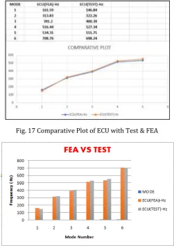
8. RESULT
From the testing & FEA results it is clear that the amplitude of ECU without stiffener is 38m/s2 and that of the ECU with stiffener is 27m/s2. So, amplitude is decreased when
stiffeners are used. The results obtained from testing &FEA are almost same. So, results are validated.
[image:7.595.50.278.284.508.2]Fig. 17 Comparative Plot of ECU with Test & FEA
Fig. 18 Comparative graph of ECU with Test & FEA
9.CONCLUSION
1. Model analysis of ECU Housing with and without stiffener has done.
2. Natural Frequency from FEA and FFT analyzer are in good relationship.
3. FEA result are in good relationship with Experimental testing result in terms of Natural Frequency.
4. From FEA result it conclude that stiffness of ECU Housing increase with inclusion of stiffener in model.
REFERENCES
1. Wang Lu, Chen Xiao-kai, Zhao Qing-hai“ Muti-objective topology optimization of an electric
vehicle’s traction battery enclosure”Science direct
Energy Procedia 88 ( 2016 ) 874 – 880.
2. Niteen T. Kakade, Pro. D.G. Gangwani “Design and Optimization of Sheet Metal Enclosure with the
Help of Behaviour Modelling ” IOSR Journal of
[image:7.595.42.287.538.685.2]© 2019, IRJET | Impact Factor value: 7.34 | ISO 9001:2008 Certified Journal
| Page 1640
3. Bikesh Kumar and Damodar Reddy “Design optimization of army radar frame(ARF) for
thermal an structural conditions”International
journal of mechanical engineering and robotics research, ISSN 2278 – 0149 www.ijmerr.com Vol. 3, No. 4.
4. Prudhvi Krishna Amburi and K Sreenivas “ Design and optimization of an antenna frame for themal
and structural conditions” ”International journal of
mechanical engineering and robotics research, ISSN 2319-5991 www.ijerst.com Vol. 3, No. 4.
5. Li Cheng, “Interior sound and vibration control
for air vehicle applications” 23rd Congress on
Sound and Vibration, Athens, Greece.
6. Titouan Fourmaux, Morvan Ouisse, Scott Cogan, Emeline Sadoulet-Reboul, “Sensitivity analysis and optimization of sheet steel thickness for
vibroacoustic behavior of enclosures” 1st
Euro-Mediterranean Conference on Structural Dynamics and Vibroacoustics (MEDYNA 2013), Jan 2013, France. pp.1 - 4, 2013. <hal-00993447>.
7. G.S. Aglietti, and C. Schwingshackl “Analysis of Enclosures and Anti Vibration Devices for Electronic Equipment for Space Applications”