Release 5 Switch Integration
Conversions
Printed in U.S.A.
Notice
Every effort was made to ensure that the information in this book was complete and accurate at the time of printing. However, information is subject to change.
Preventing Toll Fraud
“Toll fraud” is the unauthorized use of your telecommunications system by an unauthorized party (for example, a person who is not a corporate employee, agent, subcontractor, or working on your company’s behalf).
Be aware that there may be a risk of toll fraud associated with your sys- tem and that, if toll fraud occurs, it can result in substantial additional charges for your telecommunications services.
Lucent Technologies Fraud Intervention:
If you suspect that you are being victimized by toll fraud and you need technical assistance or support, call the Technical Service Center’s Toll Fraud Intervention Hotline at 1-800-643-2353.
Providing Telecommunications Security
Telecommunications security (of voice, data, and/or video communica- tions) is the prevention of any type of intrusion to (that is, either unautho- rized or malicious access to or use of your company’s
telecommunications equipment) by some party.
Your company’s “telecommunications equipment” includes both this Lucent product and any other voice/data/video equipment that could be accessed via this Lucent product (that is, “networked equipment”).
An “outside party” is anyone who is not a corporate employee, agent, subcontractor, or working on your company’s behalf. Whereas, a “mali- cious party” is anyone (including someone who may be otherwise autho- rized) who accesses your telecommunications equipment with either malicious or mischievous intent.
Such intrusions may be either to/through synchronous (time-multiplexed and/or circuit-based) or asynchronous (character-, message-, or packet-based) equipment or interfaces for reasons of:
• Utilization (of capabilities special to the accessed equipment)
• Theft (such as, of intellectual property, financial assets, or toll-facility access)
• Eavesdropping (privacy invasions to humans)
• Mischief (troubling, but apparently innocuous, tampering)
• Harm (such as harmful tampering, data loss or alteration, regardless of motive or intent)
Be aware that there may be a risk of unauthorized intrusions associated with your system and/or its networked equipment. Also realize that, if such an intrusion should occur, it could result in a variety of losses to your company (including but not limited to, human/data privacy, intellec- tual property, material assets, financial resources, labor costs, and/or legal costs).
Your Responsibility for Your Company’s Telecommunications Secu- rity
The final responsibility for securing both this system and its networked equipment rests with you – a Lucent customer’s system administrator, your telecommunications peers, and your managers. Base the fulfillment of your responsibility on acquired knowledge and resources from a vari- ety of sources including but not limited to:
• Installation documents
• System administration documents
• Security documents
• Hardware-/software-based security tools
• Shared information between you and your peers
• Telecommunications security experts
To prevent intrusions to your telecommunications equipment, you and your peers should carefully program and configure your:
Lucent Technologies does not warrant that this product or any of its net- worked equipment is either immune from or will prevent either unautho- rized or malicious intrusions. Lucent Technologies will not be responsible for any charges, losses, or damages that result from such intrusions.
Federal Communications Commission Statement
Part 15: Class A Statement. This equipment has been tested and found to comply with the limits for a Class A digital device, pursuant to Part 15 of the FCC Rules. These limits are designed to provide reasonable pro- tection against harmful interference when the equipment is operated in a commercial environment. This equipment generates, uses, and can radi- ate radio-frequency energy and, if not installed and used in accordance with the instruction manual, may cause harmful interference to radio communications. Operation of this equipment in a residential area is likely to cause harmful interference, in which case the user will be required to corect the interference at his/her own expense.
Part 15: Personal Computer Statement. This equipment has been cer- tified to comply with the limits for a Class B computing device, pursuant to Subpart J of Part 15 of FCC Rules. Only peripherals (computing input/output devices, terminals, printers, etc.) certified to comply with the Class B limits may be attached to this computer. Operation with non- certified peripherals is likely to result in interference to radio and televi- sion reception.
Part 68: Network Registration Number. This equipment is registered with the FCC in accordance with Part 68 of the FCC Rules. It is identi- fied by FCC registration number AS5USA-20411-VM-E.
Part 68: Answer-Supervision Signaling. Allowing this equipment to be operated in a manner that does not provide proper answer-supervision signaling is in violation of Part 68 rules. This equipment returns answer-supervision signals to the public switched network when:
• Answered by the called station
• Answered by the attendant
• Routed to a recorded announcement that can be administered by the CPE user
This equipment returns answer-supervision signals on all DID calls for- warded back to the public switched telephone network. Permissible exceptions are:
• A call is unanswered
• A busy tone is received
• A reorder tone is received
Canadian Department of Communications (DOC) Interference Information
This digital apparatus does not exceed the Class A limits for radio noise emissions set out in the radio interference regulations of the Canadian Department of Communications.
Le Présent Appareil Nomérique n’émet pas de bruits radioélectriques dépassant les limites applicables aux appareils numériques de la class A préscrites dans le reglement sur le brouillage radioélectrique édicté par le ministére des Communications du Canada.
Lucent Technologies Fraud Intervention
If you suspect that you are being victimized by toll fraud and you need technical support or assistance, call BCS Technical Service Center Toll Fraud Intervention Hotline at 1 800 643-2353.
European Union Declaration of Conformity
Lucent Technologies Business Communications Systems declares that the equipment specified in this document conforms to the referenced European Union (EU) Directives and Harmonized Standards listed below:
EMC Directive 89/336/EEC Low-Voltage Directive73/23/EEC
The “CE” mark affixed to the equipment
About this Book . . . vii
Intended Audience . . . vii
How This Document Is Organized . . . vii
Conventions Used . . . .viii
Related Resources . . . ix
Trademarks and Service Marks . . . x
Training . . . xi
How to Make Comments about This Document . . . xi
Conversion Checklist . . . .1-1 Overview . . . .1-1 Conversion Checklist. . . .1-1
Conversion Instructions . . . .2-1
Overview . . . .2-1
Task: 3Stop the Voice System . . . 2-7 Task: 4Backup the Lucent INTUITY System . . . 2-8 Task: 5Remove the Previous Integration Software . . . 2-11
Remove the DCIU or Mode Code Software
on the INTUITY System . . . 2-11
Task: 6Shutdown and Reboot the Lucent INTUITY System . . . 2-13
Task: 7Install the New Integration Software . . . 2-14
Task: 8Contact the Remote Support Center to Activate the Switch Integration . . . 2-17
Task: 9Administer the Lucent INTUITY System for the Integration . . . 2-18
Task: 10Remove Any Previous DCIU Switch Administration on the Switch. . . 2-20
Task: 11Administer the Switch for the Switch Integration . . . 2-21
Task: 12Remove the Old DCIU Switch Hardware from the Switch . . . 2-23
Task: 13Shutdown the Lucent INTUITY System . . . 2-24
Task: 14Remove the Install Hardware. . . 2-26
MAP/5P and MAP/5PV3 Instructions . . . 2-26
MAP/5P and MAP/5PV3: Remove the Dress Cover . . . 2-26
MAP/5P and MAP/5PV3: Install or Remove Circuit Cards . . . 2-29
MAP/40P Instructions. . . 2-34
MAP/40P: Open the MAP . . . 2-34
MAP/40P: Install or Remove Circuit Cards. . . 2-35
MAP/100P Instructions. . . 2-39
Open the MAP/100P. . . 2-39
MAP/100P: Install or Remove Circuit Cards . . . 2-41
Task: 15Connect the Lucent INTUITY System to the Switch . . . 2-45
Cable the Voice Ports. . . 2-45
Connecting the Tip/Ring Circuit Card. . . 2-46
Direct Cable Connection . . . 2-46
Cable Connection Using a Line Splitter . . . 2-48
Cable the Switch Link . . . 2-49
Connect the LAN Link . . . 2-49
Parts List. . . 2-50
Distance Limits. . . 2-50
Cabling Diagram . . . 2-50
Alternate Crossover Wiring . . . 2-52
Connect the DCIU. . . 2-52
Connections through an IDI . . . 2-52
Task: 16Apply Power to the System . . . 2-54
Task: 17Administer and Test the LAN Link . . . 2-54
Administer TCP/IP LAN Connectivity . . . 2-55
Administer the LAN for Lucent I
NTUITY. . . 2-55
Establish Network Addresses . . . .2-58 Reboot the System and Attach the LAN Cable . . . .2-60 Task: 18Remap and Test the Channels . . . .2-62 Stop the Voice System. . . .2-63 Map Channels to Switch Extensions. . . .2-64 Start the Voice System . . . .2-67 Perform Acceptance Testing . . . .2-67 Verify Channel State. . . .2-68 Determine the Channel State . . . .2-68 Change the Channel State . . . .2-69 Assign the ChanTran Service and Test the Channels . . . .2-70 Assign the ChanTran Service. . . .2-71 Test the Channels . . . .2-72 Reassign Services to DNIS . . . .2-76 Verify On-Hook Status. . . .2-78 Assign Services to Called Numbers . . . .2-78 Map Services to Channels for Operation . . . .2-81 Task: 19Change Extension Length . . . .2-83 Busyout the Voice Ports . . . .2-84 Busyout the Networking Ports . . . .2-85 Changing a Block of Extensions
(with Extension Length Change) . . . .2-86
Changing a Block of Extensions (without Extension Length Change) . . . .2-89
Release the Voice Ports . . . .2-92
Release the Networking Ports . . . .2-94
Task: 20Test the LAN Link. . . .2-95
Task: 21Place Test Calls to the System. . . .2-95
Task: 22Change the CAS Switch Assignment . . . .2-96
Task: 23Clear Any Alarms . . . .2-96
Task: 24Assign the System Date and Time. . . .2-98
This document, Lucent INTUITY™ Messaging Solutions Release 5 Switch Integration Conversions, Issue 1, contains the procedures needed to convert a Release 5 Lucent INTUITY system switch to one of the following switches:
n
DEFINITY® CLAN
n
DEFINITY® DCIU
n
MERLIN LEGEND® or MERLIN® MAGIX™ Mode Code
n
DEFINITY® PROLOGIX™ or DEFINITY® BCS Mode Code
Intended Audience
This document is intended for on-site technicians and remote
maintenance center personnel supporting a Lucent INTUITY switch
conversion.
n
Chapter 2, ‘‘Conversion Instructions’’
This chapter presents the procedures needed to convert Lucent INTUITY Release 5
Systems to DEFINITY CLAN, DEFINITY DCIU, MERLIN LEGEND, and ProLogix/DEFINITY Mode Code integrations.Conventions Used
The following conventions are used in this book:
n
The word “type” means to press the key or keys specified. For example, an instruction to type the letter “y” is shown as
Type y to continue.
n
The word “enter” means to type a value and then press the enter key. For example, an instruction to type the letter “y” and press
is shown as Enter y to continue.
n
Keys on a terminal or PC are in rounded boxes. For example, an instruction to press the enter key is shown as
Press .
n
Function keys on a terminal, PC, or system screens, also known as soft keys, are in round boxes followed by the function or value.
For example, an instruction to press function key 3 is shown as Press (Choices).
n
Keys that you press on a telephone keypad are in square boxes.
For example, an instruction to press the first key on a telephone keypad is shown as
Press to record a message.
n
Values, messages, field names, and prompts that appear on the system are in typewriter-style constant-width type, as shown in the following:
Press <Enter> to continue.
ENTER
ENTER
F3
1
n
The sequence of menu options that you must select are shown in boxes, for example:
Start at the Lucent INTUITY Main Menu and select:
In the above example, you would display the Lucent Intuity Main Menu and then select Customer/Service Administration. From the Customer/Service Administration menu, you would select Alarm Management.
n
Commands and text to type in or enter are in bold type, as in the following:
Enter change-switch-time-zone at the enter command:
prompt.
n
Command variables are in bold italic type when they are part of what you must type in and regular italic type when they are not:
Enter ch ma machine_name, where machine_name is the name of the call delivery machine you just created.
Related Resources
The following documentation for Release 5 systems is available on CD-ROMs:
n
INTUITY Messaging Solutions Release 5 Documentation, 585-313-803, Issue 2
> Alarm Management
> Customer/Services Administration
Trademarks and Service Marks
The following trademarked products are mentioned in this book:
n
AT is a trademark of Hayes Microcomputer Products, Inc.
n
AUDIX is a registered trademark of Lucent Technologies.
n
COMSPHERE is a registered trademark of Paradyne Corporation.
n
DEFINITY is a registered trademark of Lucent Technologies.
n
DMS-100 is a is a trademark of Northern Telecom Limited.
n
Equinox is a trademark of Equinox Systems, Inc.
n
Intuity is a trademark of Lucent Technologies.
n
Lucent is a trademark of Lucent Technologies.
n
Meridian is a trademark of Northern Telecom Limited.
n
MERLIN LEGEND is a registered trademark of Lucent Technologies.
n
Microsoft is a registered trademark of Microsoft Corporation.
n
MS is a registered trademark of Microsoft Corporation.
n
MS-DOS is a registered trademark of Microsoft Corporation.
n
Mitel is a trademark of Mitel Corporation.
n
NEAX is a trademark of NEC Telephone, Inc.
n
Northern Telecom is a registered trademark of Northern Telecom Limited.
n
Novell is a registered trademark of Novell, Inc.
n
ORACLE is a trademark of Oracle Corporation.
n
Paradyne is a registered trademark of AT&T.
n
Phillips is a registered trademark of Phillips Screw Company.
n
Rolm is a registered trademark of International Business Machines.
n
Siemens is a registered trademark of Siemens Aktiengellschaft.
n
SL-1 is a trademark of Northern Telecom Limited.
n
UNIX is a registered trademark of Novell.
n
VB-PC is a trademark of Voice Technologies Group, Inc.
n
VT100 is a trademark of Digital Equipment Corporation.
n
Windows is a trademark of Microsoft Corporation
Training
For more information on training for the Lucent INTUITY and other Lucent products, visit the Lucent Technologies training web site at www.lucenttraining.com.
How to Make Comments about This Document
We are interested in your suggestions for improving this book. Please send us your comments and suggestions using any of the following mail methods:
Post Office:
Lucent Technologies
Communications Applications Group, Technical Publications Room 22-2H15
11900 North Pecos Street Denver, Colorado 80234 Email:
Fax or voice mail:
Overview
This chapter contains a checklist of procedures needed for the Lucent INTUITY Messaging Solutions Release 5 switch integration conversions.
! CAUTION:
Follow these procedures in the order listed. Do not omit any steps from the procedures unless they are optional for a specific system. Leaving out steps can cause the conversion to fail.
Conversion Checklist
Table 1-1 provides the checklist of tasks for Lucent INTUITY Release 5 System conversion to one of the following switches:
n
DEFINITY® CLAN
n
NSAC at 1-800-552-3293. For all other integration types, call 1-800-248-1234.
Table 1-1. INTUITY Messaging Solutions R5 Switch Integration Conversions Checklist
Task Description See ✔
1 Stop Alarm Origination page 2-2
2 Busyout the Link: Lucent DEFINITY Switch Integration Only
page 2-4
3 Stop the Voice System page 2-7
4 Backup the Lucent INTUITY System page 2-8 5 Remove the Previous Integration
Software
page 2-11
6 Shutdown and Reboot the Lucent INTUITY System
page 2-13
7 Install the New Integration Software page 2-14 8 Contact the Remote Support Center to
Activate the Switch Integration
page 2-17
9 Administer the Lucent INTUITY System for the Integration
page 2-18
10 Remove Any Previous DCIU Switch Administration on the Switch
page 2-20
11 Administer the Switch for the Switch Integration
page 2-21
12 Remove the Old DCIU Switch Hardware from the Switch
page 2-23
13 Shutdown the Lucent INTUITY System page 2-24
14 Remove the Install Hardware page 2-26
15 Connect the Lucent INTUITY System to the Switch
page 2-45
16 Apply Power to the System page 2-54
17 Administer and Test the LAN Link page 2-54
18 Remap and Test the Channels page 2-62
19 Change Extension Length page 2-83
20 Test the LAN Link page 2-95
21 Place Test Calls to the System page 2-95 22 Change the CAS Switch Assignment page 2-96
23 Clear Any Alarms page 2-96
24 Assign the System Date and Time page 2-98
25 Stop the Voice System page 2-100
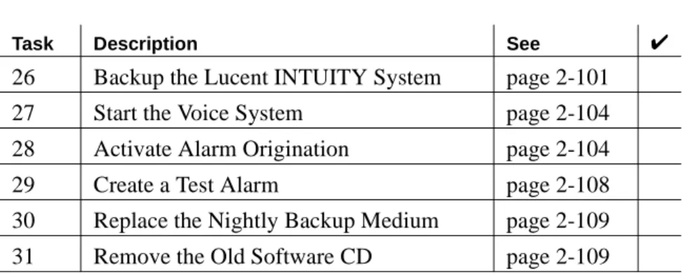
26 Backup the Lucent INTUITY System page 2-101
27 Start the Voice System page 2-104
28 Activate Alarm Origination page 2-104
29 Create a Test Alarm page 2-108
30 Replace the Nightly Backup Medium page 2-109
31 Remove the Old Software CD page 2-109
Table 1-1. INTUITY Messaging Solutions R5 Switch Integration Conversions Checklist (Continued)
Task Description See ✔
(2 of 2)
Overview
This section describes how to convert INTUITY Messaging Solutions Release 5 systems to one of the following switches:
n
DEFINITY® CLAN
n
DEFINITY® DCIU
n
MERLIN LEGEND® or MERLIN® MAGIX™ Mode Code
n
DEFINITY® PROLOGIX™ or DEFINITY® BCS Mode Code
! CAUTION:
Follow the steps in these instructions in the exact order in which they appear. Failure to follow the instructions in this
document in the exact order will result in conversion failure.
For technical assistance with Lucent INTUITY™ systems integrated with
MERLIN LEGEND® Communications System or a System 25, call the
NSAC at 1-800-552-3293. For all other integration types, call
Task 1: Stop Alarm Origination
This procedure inactivates alarm origination so that the Lucent INTUITY system does not inform the remote support center of any alarms that occur during the update process.
Note:
Note:
If the system does not have alarm origination and is not integrated with a DEFINITY® communications system, continue with Task 3,
‘‘Stop the Voice System,’’ on page 2-7. If the system is integrated with a DEFINITY system, continue with Task 2, ‘‘Busyout the Link: Lucent DEFINITY Switch Integration Only,’’ on page 2-4.
To inactivate alarm origination:
1. Login as craft
2. Press to accept the AT386 default.
The system displays the Lucent INTUITY Main Menu (Figure 2-1).
3. From the Lucent INTUITY Main Menu select:
Figure 2-1. Lucent INTUITY Main Menu
ENTER
> Alarm Management
> Customer/Services Administration
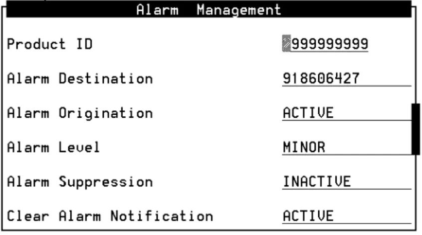
The system displays the Alarm Management window (Figure 2-2).
4. Move the cursor to the
Alarm Originationfield.
5. Press (Choices).
The system displays the Alarm Origination menu (Figure 2-3)
6. Select
INACTIVE.
The system changes the entry in the
Alarm Originationfield to
INACTIVE.
7. Press (Save).
The system displays an Information window (Figure 2-4).
Figure 2-2. Alarm Management Window
Figure 2-3. Alarm Origination Menu
F2
F3
9. Press (Cancel) two times to return to the Lucent INTUITY Main Menu.
10. Determine your next step:
n
If the system is integrated with a DEFINITY switch, continue with Task 2, "Busyout the Link: Lucent DEFINITY Switch Integration Only."
n
If the system is not integrated with a DEFINITY switch, continue with Task 3, ‘‘Stop the Voice System,’’ on page 2-7.
Task 2: Busyout the Link: Lucent DEFINITY Switch Integration Only
For Lucent INTUITY systems integrated with a DEFINITY
Communications System, you must busyout the physical link to prevent the switch from calling out alarms during the update.
For System 75, G1, G3, and R5/6/7/8 Switches with DCIU Integration
To busyout the link, go to the DEFINITY switch monitor, and perform the following steps:
1. Enter busy link n
Where n is the number of the physical link to the Lucent INTUITY system. n may be any integer from 1 to 8.
2. Continue with Task 3, ‘‘Stop the Voice System,’’ on page 2-7.
For System R7 Switches with CLAN Integration
To busyout the link, perform the steps in the following two procedures:
F6
Identify the Host Name
1. From the Lucent INTUITY Main Menu (Figure 2-1), select:
2. Locate and write down the host name that appears in the Host Name field.
3. Press (Cancel) twice to return to the Lucent INTUITY Main Menu.
4. Continue with ‘‘Busyout the Link.’’
Busyout the Link
1. Go to the DEFINITY switch monitor and enter change communication-interface processor-channels
2. In the Destination Node column, move the cursor to the host name that you wrote down in the ‘‘Identify the Host Name’’
procedure, step 2.
3. Enter n in the Enable column.
4. Press on the numeric keypad.
5. Continue with Task 3, ‘‘Stop the Voice System,’’ on page 2-7.
For System R8 Switches with CLAN Integration
To busyout the link, perform the steps in the following two procedures:
Identify the Host Name
> Network Addressing
> TCP/IP Administration
F6
ENTER
4. Continue with ‘‘Busyout the Link.’’
Busyout the Link
1. Go to the DEFINITY switch monitor and enter change communication-interface processor-channels
2. In the Node Name column, move the cursor to the host name that you wrote down in the ‘‘Identify the Host Name’’ procedure, step 2.
3. Enter n in the Enable Eth Pt column.
4. Press on the numeric keypad.
5. Continue with Task 3, ‘‘Stop the Voice System,’’ on page 2-7.
For System 85 and G2 Switches
To busyout the link, go to the DEFINITY switch monitor, and perform the following steps:
1. Enter proc650 test 3
2. Press the busyout key twice to busyout the physical link to the Lucent INTUITY system.
3. Continue with Task 3, "Stop the Voice System."
ENTER
Task 3: Stop the Voice System
The following procedure describes how to stop the Lucent INTUITY voice system so that you can backup the system and install the new software.
1. Start at the Lucent INTUITY Main Menu (Figure 2-1) and select:
The system displays the System Control screen (Figure 2-5).
2. Select
Stop Voice System.
The system displays the Wait Time window (Figure 2-6).
3. Type 60 in the Wait Time window and press to save the wait time.
The system responds by waiting 60 seconds and then stops the
Figure 2-5. System Control Screen
Figure 2-6. Wait Time Window
> System Control
> System Management
> Customer/Services Administration
F3
4. Press (Cancel) two times.
The system displays the Customer/Services Administration menu.
5. Continue with Task 4, "Backup the Lucent INTUITY System."
Task 4: Backup the Lucent INTUITY System
A backup is the only way to ensure the system can recover in the event of an equipment failure or power failure, or problems with the update.
To perform a full system backup:
1. From the Customer/Services Administration menu, select:
If the system uses tape cartridges, the following message appears:
Please insert a tape cartridge.
Press Enter to continue or Delete to quit
2. Insert a tape cartridge or disk cartridge.
F6
Note:
Note:
Do not use the nightly backup tape cartridge or disk cartridge.
> Backup
> Backup/Restore
3. Press .
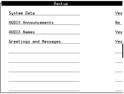
The system displays the Backup window (Figure 2-7).
4. Enter y in the fields to be backed up.
5. Enter n in all other fields.
6. Press (Save).
n
If your system uses disk cartridges, the following message
Figure 2-7. Backup Window
Note:
Note:
The screen displays fields based on the system’s configuration and may differ from this illustration.
Note:
Note:
If the system does not have customized announcements, do not backup AUDIX Announcements.
ENTER
F3
n
If your system uses tape cartridges, the following message appears:
Backup starting Day Date Time.
Mounting backup device Day Date Time.
/backup1 successfully mounted.
7. Determine your next step:
n
If additional backup media is necessary, remove the backup medium, label it with the current date and type of backup data, and insert the new media.
n
If additional backup media is not necessary, continue with step 8.
8. When the backup is complete, the system displays the following message:
successfully ran post-backup scripts.
Verifying backup.
Backup verified.
Unmounting /X.
Backup completed successfully - Day Date Time.
Press Enter to continue
9. Press .
10. Press (Cancel) three times to return to the Lucent INTUITY Main Menu (Figure 2-1).
11. Continue with Task 5, "Remove the Previous Integration Software."
Note:
Note:
For systems that use tape cartridges as a backup medium, X equals backup1. For systems that use disk cartridges as a backup medium, X equals rscd.
ENTER
F6
Task 5: Remove the Previous Integration Software
This section assumes that the DEFINITY switch is already Release 7.1 or later. If it is not, upgrade the switch first and then return to these
procedures.
Remove the DCIU or Mode Code Software on the INTUITY System
1. Start at the Lucent INTUITY Main Menu (Figure 2-1) and select:
2. Check whether the DCS option is enabled for this system. If it is, the feature must be re-enabled after you install the new software.
3. Press (Cancel) to return to the Customer/Services Administration menu.
4. At the Customer/Services Administration menu, select:
The system displays the Software Management screen.
5. Highlight Software Removal and press .
The system displays the Software Removal screen with a list of software packages.
Depending on the integration type, one of the following software packages in Table 2-1 needs to be removed.
> Feature Options
F6
> Software Management
ENTER
6. Press the
UP ARROW key and the DOWN ARROW keyto highlight the package you want to remove.
7. Press .
The system places an X next to the package you selected.
8. Press the
DOWN ARROW keyuntil the cursor highlights Remove Selected Packages.
You may need to advance several screens.
9. Press .
Verify that you are removing the correct package, and answer y to any questions that the system displays.
10. When the Selected Packages prompt returns, press q to return to the Lucent INTUITY Main Menu.
11. Continue with Task 6, "Shutdown and Reboot the Lucent INTUITY System."
ROLMset Used for integration with Rolm switches via VBPC card
SWINset The following are SWINset packages:
n
NEC NEAX (serial connection)
n
Siemens HICOM (serial connection)
n
Ericsson (serial connection)
n
MERLIN LEGEND (mode code)
n
DMS100 (serial connection)
n
Intecom (serial connection)
n
Norstar (mode code)
n
System 25 (mode code)
n
5ESS (serial connection)
n
DEFINITY Mode Code (mode code Lucent Technologies)
Package Name Integration Type
(2 of 2)
ENTER
ENTER
Task 6: Shutdown and Reboot the Lucent INTUITY System
The following procedure describes how to reboot the system.
1. Start at the Lucent INTUITY Main Menu (Figure 2-1) and select:
The system displays the Wait Time window (Figure 2-8).
2. Enter 0 (zero) for an immediate shutdown.
3. Press (Save).
The system displays the following message:
Voice system is already stopped.
Shutdown started.
When the system is completely shut down, the system displays the following message.
Figure 2-8. Wait Time Window
> Shutdown System
> System Control
> System Management
> Customer/Services Administration
F3
Task 7: Install the New Integration Software
Important:
If you are installing this software from a newer version of the INTUITY AUDIX CD-ROM than the version that was previously used to load the system, the system may inform you of software packages that need to be updated. Allow the system to update.
Discard any previous INTUITY AUDIX CD-ROMs. Keep only the current INTUITY AUDIX CD-ROM.
To install the new switch integration package:
1. Login as craft.
2. Insert the INTUITY AUDIX CD-ROM in the CD-ROM drive.
3. From the Lucent INTUITY Main Menu, select:
The system displays the Software Install warning message:
Lucent Technologies INTUITY/AUDIX - Software Install (p1 of X)
***SOFTWARE INSTALL***
These installed packages need to be updated.
Below is a list of versions of software on the install media that will be updated.
You may need to press SPACEBAR in order to see more package selection sand see the action items.
Depending on the integration type, one of the following switch integration packages in Table 2-2 need to be installed.
! CAUTION:
If you did not backup the system in Task 4, ‘‘Backup the Lucent INTUITY System,’’ on page 2-8, backup the system before you continue with this procedure.
> CD
> Software Installation
> Software Management
Table 2-2. Switch Integration Software Packages To Be Installed
If you did not complete the backup, the system displays the following Backup Warning message:
A successful backup has not been completed in the past 2 hours. In the
unlikely event of a catastrophic failure during this upgrade procedure, a
full system backup may be the only method of recovering the customer’s
data. Doing a full system backup is HIGHLY recommended.
Do you want to continue with the upgrade anyway?
( ) Yes, continue this operation without full system backup
(*) No, quit this operation in order to complete full system backup
Continue Help
Package Name Integration Type
LANset CLAN
DCIUset DCIU
Mode Code MERLIN LEGEND, MERLIN MAGIX, or DEFINITY PROLOGIX Mode Code
! CAUTION:
If you did not backup the system in Task 4, ‘‘Backup the Lucent INTUITY System,’’ on page 2-8, backup the system before you continue with this procedure.
set (V2)
You may need to advance several screens.
5. Press .
The system displays the line in the following manner:
[X] DCIUset 3.2-7 -- INTUITY Platform DCIU set (V2)
You can only install one switch integration package on the system.
6. Mark the appropriate entries for additional packages, by highlighting them and pressing the key.
7. Press the
DOWN ARROW keyuntil the cursor highlights the following message:
Install selected packages
You will scroll through several screens.
8. Press .
The system lists the packages that you selected:
You selected the following packages from the CD:
*DCIUset -- Est. Installation Time: 5 minutes
Total Estimated Installation time is 0 hours and 5 minutes.
PROCEED Help
Back to selection form Back to main menu
9. Make sure that the cursor is on PROCEED.
! CAUTION:
If you are installing multiple software packages, select all of them before proceeding to step 7.
Loading the packages one at a time will require several system reboots. This will extend the amount of time the voice system will be out of service.
ENTER
ENTER
ENTER
10. Press .
The system installs the package then displays the following message:
Do you have more media from which to install more software?
11. Enter n
The system displays the following message:
Do you have hardware to install?
12. Enter n
The system automatically reboots.
13. Continue with Task 8, "Contact the Remote Support Center to Activate the Switch Integration."
Task 8: Contact the Remote Support Center to Activate the Switch Integration
To activate the switch integration, contact the remote support center.
Do not continue with the tasks in this document until the switch integration is active.
ENTER
Task 9: Administer the Lucent INTUITY System for the Integration
Administer the INTUITY System for the integration.
For: see:
DEFINITY CLAN Chapter 4, "Lucent INTUITY System Administration for Switch Integration,"
page 4-1, of INTUITY Messaging Solutions Using a LAN to Integrate with DEFINITY ECS, 585-313-604, Issue 1.
After administering the Lucent INTUITY system, determine your next step:
n
If you are removing a DCIU integration, continue with Task 10, "Remove Any Previous DCIU Switch Administration on the Switch."
n
If you are not removing a DCIU integration, continue with Task 11,
‘‘Administer the Switch for the Switch Integration,’’ on page 2-21.
DEFINITY DCIU For DEFINITY Release 5 and 6, see Chapter 3, "System 75 and DEFINITY Generic 1 Administration," page 3-1, of I
NTUITYMessaging Solutions Integration with System 75, DEFINITY Generics 1 & 3, and R5/6, 585-310-257, Issue 2.
After administering the Lucent INTUITY system, continue with Task 11, ‘‘Administer the Switch for the Switch Integration,’’ on page 2-21.
(1 of 2)
MERLIN
LEGEND/MAGIX Communications Systems
Chapter 5, "MERLIN LEGEND Switch Administration," page 5-1, of I
NTUITYIntegration with MERLIN LEGEND Communications System, 585-310-255, Issue 1.
After administering the system, determine your next step:
n
If you are removing a DCIU integration, continue with Task 10, "Remove Any Previous DCIU Switch Administration on the Switch."
n
If you are not removing a DCIU integration, continue with Task 11,
‘‘Administer the Switch for the Switch Integration,’’ on page 2-21.
ProLogix/DEFINITY Mode Code
For DEFINITY Release 5 and 6, see Chapter 6, "DEFINITY Mode-Code Switch
Integration," page 6-1, of I
NTUITYMessaging Solutions Integration with System 75, DEFINITY Generics 1 & 3, and R5/6, 585-310-257, Issue 2.
After administering the system, determine your next step:
n
If you are removing a DCIU integration, continue with Task 10, "Remove Any Previous DCIU Switch Administration on the Switch."
n
If you are not removing a DCIU integration, continue with Task 11,
‘‘Administer the Switch for the Switch Integration,’’ on page 2-21.
For: see:
(2 of 2)
Task 10: Remove Any Previous DCIU Switch Administration on the Switch
Note:
Note:
Record all existing link administration in case you must revert to the old setup.
Complete the following steps to remove previous DCIU switch Administration on the switch:
1. If using DCIU integration:
a. Remove the existing X.25 data module assignment from the switch.
b. Remove the X.25 processor channels from the switch.
2. If using Mode Code integration, disable Mode Code on the change system-parameters customer-options screen.
3. Continue with Task 11, "Administer the Switch for the Switch
Integration."
Task 11: Administer the Switch for the Switch Integration
Administer the switch for the switch integration.
For: see:
DEFINITY CLAN Chapter 3, "Administration for
Switch-to-Lucent I
NTUITYSystem Link,"
page 3-1, of INTUITY Messaging Solutions Using a LAN to Integrate with DEFINITY ECS, 585-313-604, Issue 1.
After administering the switch, determine your next step:
n
If you are removing a DCIU integration, continue with Task 12,
"Remove the Old DCIU Switch Hardware from the Switch."
n
If you are not removing a DCIU integration, continue with Task 13,
‘‘Shutdown the Lucent INTUITY System,’’ on page 2-24.
DEFINITY DCIU For DEFINITY Release 5 and 6, see Chapter 3, "System 75 and DEFINITY Generic 1 Administration," page 3-1, of I
NTUITYMessaging Solutions Integration with System 75, DEFINITY Generics 1 & 3, and R5/6, 585-310-257, Issue 2.
After administering the switch, continue with Task 12, "Remove the Old DCIU Switch Hardware from the Switch."
(1 of 2)
MERLIN
LEGEND/MAGIX Communications Systems
Chapter 5, "MERLIN LEGEND Switch Administration," page 5-1, of INTUITY Integration with MERLIN LEGEND Communications System, 585-310-255, Issue 1.
After administering the switch, determine your next step:
n
If you are removing a DCIU integration, continue with Task 12,
"Remove the Old DCIU Switch Hardware from the Switch."
n
If you are not removing a DCIU integration, continue with Task 13,
‘‘Shutdown the Lucent INTUITY System,’’ on page 2-24.
ProLogix/DEFINITY Mode Code
For DEFINITY Release 5 and 6, see Chapter 6, "DEFINITY Mode-Code Switch Integration," page 6-1, of INTUITY Messaging Solutions Integration with System 75, DEFINITY Generics 1 & 3, and R5/6, 585-310-257, Issue 2.
After administering the switch, determine your next step:
n
If you are removing a DCIU integration, continue with Task 12,
"Remove the Old DCIU Switch Hardware from the Switch."
n
If you are not removing a DCIU integration, continue with Task 13,
‘‘Shutdown the Lucent INTUITY System,’’ on page 2-24.
For: see:
(2 of 2)
Task 12: Remove the Old DCIU Switch Hardware from the Switch
! CAUTION:
Do not remove the cabling that connects the Lucent INTUITY system and the DEFINITY ECS voice ports.
To remove the old DCIU Switch Hardware from the Switch:
1. Disconnect the cabling from the processor interface (PI) port or packet gateway port (PGATE) used for DCIU connectivity on the switch.
2. If a data module or modem was used for the connection, disconnect that equipment from service.
3. Remove old circuit packs from the switch (only for si and r models):
a. Power down the switch.
b. For an si model, remove the TN765 processor interface (PI) circuit pack unless it is being used for X.25 connections.
4. For an r model, remove the TN577 packet gateway (PGATE) circuit pack unless it is being used for X.25 connections 5. Continue with Task 13, "Shutdown the Lucent INTUITY
System."
Task 13: Shutdown the Lucent INTUITY System
The following procedure describes how to shut down the system.
1. Start at the Lucent INTUITY Main Menu (Figure 2-1) and select:
The system displays the Wait Time window (Figure 2-9).
2. Enter 0 (zero) for an immediate shutdown.
3. Press (Save).
The system displays the following message:
Voice system is already stopped.
Shutdown started.
When the system is completely shut down, the system displays the following message.
The system is down.
Figure 2-9. Wait Time Window
> Shutdown System
> System Control
> System Management
> Customer/Services Administration
F3
Press any key to reboot your computer.
4. Determine your next step:
Integration Action
DEFINITY CLAN Check the system for a LAN circuit card (Figure 2-13 on page 2-32)
n
If the system does not have a LAN circuit card installed, continue with Task 14, "Remove the Install Hardware."
n
If the system has a DCIU circuit card (GP Synch or EICON) installed, continue with Task 14,
"Remove the Install Hardware."
n
If the system has a LAN circuit card and does not have a DCIU card, continue with Task 15, ‘‘Connect the Lucent INTUITY System to the Switch,’’ on page 2-45.
DEFINITY DCIU Install a DCIU (EICON) circuit card (Figure 2-12 on page 2-30), continue with Task 14, "Remove the Install Hardware."
MERLIN
LEGEND/MAGIX and ProLogix/
DEFINTITY Mode Code
Check the system for a DCIU circuit card (GP Synch or EICON) (Figure 2-12 on page 2-30)
n
If the system has a DCIU circuit card (GP Synch or EICON) installed, continue with Task 14,
"Remove the Install Hardware."
n
If the system does not have a DCIU circuit card (GP Synch or EICON) installed, continue with Task 15,
‘‘Connect the Lucent INTUITY
Task 14: Remove the Install Hardware
Note:
Note:
This task is not needed for any conversion that does not need to have a DCIU/GP-Synch circuit card removed or a LAN card installed
The removal and installation instructions differ for each of the following platforms.
MAP/5P and MAP/5PV3 Instructions
For additional information about the MAP/5P, see INTUITY
Messaging Solutions Release 5 Documentation for Technicians, 585-313-807, Issue 2.
MAP/5P and MAP/5PV3: Remove the Dress CoverTo remove the dress cover:
1. Turn off the front power switch and remove the incoming AC line.
2. Tag the power cord plugs with a note indicating that no one other than yourself should reconnect power to this equipment.
3. Disconnect keyboard and monitor cords.
4. Disconnect the LAN cable and any cables that will restrict access to the system.
5. Place the dress cover lock (Figure 2-10, #9) in the open position.
For this platform: see:
MAP/5P and MAP/5PV3 below, this page
MAP/40P page 2-34
MAP/100P page 2-39
! DANGER:
Shut power off before removing the dress cover.
Note:
Note:
Figure 2-10 shows the dress cover lock in the locked position.
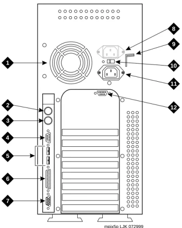
Figure 2-10. Back View of the MAP/5P and MAP/5PV3
mpix5p LJK 072999
1
2 3 4
5
6
7
8 9
10
11
12
1 Power supply fan exhaust 2 Keyboard connector 3 Mouse connector (not used) 4 COM1
5 COM2 (MAP/5P) or USB ports (MAP/5PV3, not used) 6 Parallel port
7 Monitor connector
8 AC power supply outlet (MAP/5P only) 9 Dress cover lock
10 AC voltage selector switch 11 AC power inlet receptacle 12 COM2 (MAP/5PV3 only)
6. Simultaneously compress the dress cover latches on both sides of the MAP/5P and MAP/5PV3 (Figure 2-11, #1).
7. Slide the dress cover away from the MAP/5P and MAP/5PV3.
8. Continue with ‘‘MAP/5P and MAP/5PV3: Install or Remove Circuit Cards.’’
Figure 2-11. Removing the Dress Cover
Dress cover latch
MAP/5P and MAP/5PV3: Install or Remove Circuit Cards
Install or remove circuit cards as needed. The final configuration for the MAP should be:
Integration Configuration
DEFINITY CLAN The DEFINITY CLAN integration does not require a switch integration circuit card. It does, however, require a LAN circuit card installed in PCI Slot #2
DEFINITY DCIU The DEFINITY DCIU integration requires a DCIU circuit card (EICON) installed in any ISA slot MERLIN
LEGEND/MAGIXs Communications Systems
The MERLIN LEGEND/MAGIXs Communications Systems do not use a switch integration or LAN circuit card for the integration
ProLogix/DEFINITY Mode Code
The ProLogix/DEFINITY Mode
Code integrations do not use a switch
integration or LAN circuit card for
the integration
MAP/5P and MAP/5PV3: Remove the DCIU Circuit Card (GP Synch or EICON).
Use the following procedure to remove a DCIU circuit card (GP Synch or EICON) (Figure 2-12):
1. Locate the circuit card (Figure 2-12) to be replaced within the card cage.
2. Disconnect any attached cables.
3. If there are cables attached to other circuit cards which would impede the removal of the circuit card, disconnect them and place them to the side.
4. Remove the retaining screw from the circuit card faceplate and save it.
5. Remove the circuit card from the backplane slot by gently pulling on each corner of the circuit card.
6. Remove the circuit card from the MAP/5P or the MAP/5PV3.
7. Replace the slot cover.
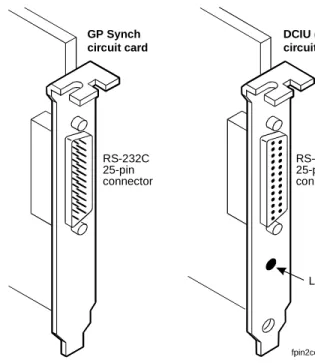
Figure 2-12. GP Synch or DCIU (EICON) Circuit Card Faceplates
Note:
Note:
Pay close attention to the connectivity of each cable.
RS-232C 25-pin connector
RS-232C 25-pin connector
LED (green) GP Synch
circuit card
DCIU (EICON) circuit card
fpin2cd2 KLC 052898
8. Determine your next step:
n
If you are converting to a CLAN or DCIU integration, continue with ‘‘MAP/5P and MAP/5PV3: Install Circuit Cards.’’
n
If you are not converting the system to a CLAN integration, continue with ‘‘MAP/5P and MAP/5PV3: Close the MAP’’
on page 33.
MAP/5P and MAP/5PV3: Install Circuit Cards.
If you are converting the system to a CLAN or a DCIU integration, complete the following steps. The CLAN integration requires a LAN circuit card. The DCIU integration requires a DCIU circuit card (EICON).
Note:
Note:
The INTUITY system only uses one LAN Circuit Card. Do not install two LAN or DCIU circuit cards into the system.
1. Unpack the new circuit card from its ESD protective wrapping.
n
Figure 2-12 shows the DCIU circuit card.
n
Figure 2-13 shows the LAN circuit card.
Note:
Note:
The DCIU and LAN circuit cards do not have jumpers or switches that need to be set.
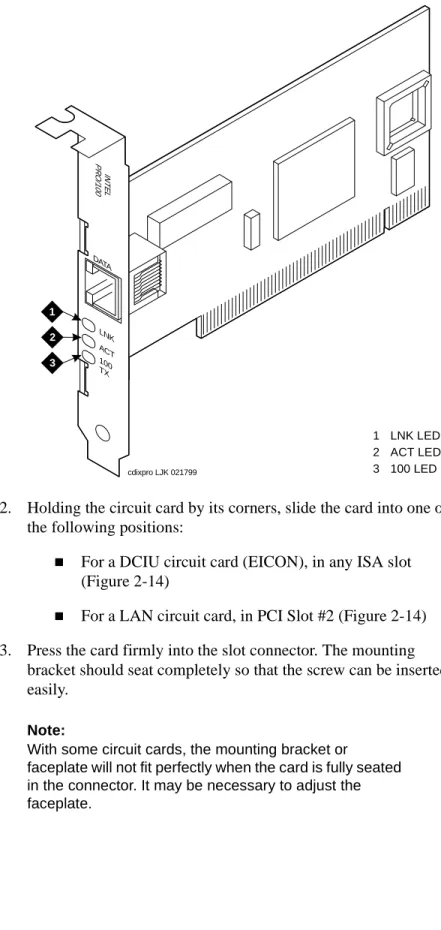
2. Holding the circuit card by its corners, slide the card into one of the following positions:
n
For a DCIU circuit card (EICON), in any ISA slot (Figure 2-14)
n
For a LAN circuit card, in PCI Slot #2 (Figure 2-14) 3. Press the card firmly into the slot connector. The mounting
bracket should seat completely so that the screw can be inserted easily.
Figure 2-13. LAN Circuit Card
Note:
Note:
With some circuit cards, the mounting bracket or
faceplate will not fit perfectly when the card is fully seated in the connector. It may be necessary to adjust the faceplate.
LNK DATA
ACT 100 TX
INTELPRO/100
cdixpro LJK 021799 1
2 3
1 LNK LED 2 ACT LED 3 100 LED
4. Secure the circuit card faceplate into position by replacing the Phillips head retaining screw.
5. Continue with ‘‘MAP/5P and MAP/5PV3: Close the MAP’’
MAP/5P and MAP/5PV3: Close the MAP.
To close the map:
1. Align the dress cover with the MAP/5P and MAP/5PV3 chassis.
2. Slide the dress cover back until it locks into place.
3. Close the dress cover lock on the back of the MAP/5P and MAP/5PV3 chassis.
4. Reconnect any cords or lines that you removed from the system.
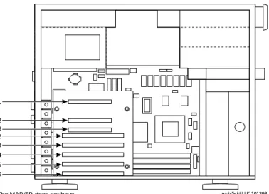
Figure 2-14. MAP/5P and MAP/5PV3 Internal Layout
Note:
Note:
Do not connect the LAN cable at this time. Wait until instructed to do so.
mpix5sid LJK 101298 PCI slot 1
PCI slot 2 PCI slot 3 ISA slot 2 ISA slot 3 ISA slot 4 ISA slot 5 ISA slot 6
NOTE: The MAP/5P does not have an ISA slot 1 available for use.
n
If you are installing CLAN or DCIU integration, continue with Task 15, "Connect the Lucent INTUITY System to the Switch."
n
If you are installing a mode-code integration and the ports are still connected, continue with Task 16, ‘‘Apply Power to the System,’’ on page 2-54.
MAP/40P Instructions
For additional information about the MAP/40P, see INTUITY
Messaging Solutions Release 5 Documentation for Technicians, 585-313-807, Issue 2.
MAP/40P: Open the MAP1. Turn off the power switch.
2. Remove the incoming AC power cord, keyboard, and video cord.
3. Tag the power cord plug with a note indicating that no one other than you should reconnect power to this equipment.
4. Set the MAP/40P tower upright on the support base.
5. Remove the front bezel by pulling it forward (Figure 2-15, #1).
6. Remove the six screws located along the bottom of the MAP/40P (Figure 2-15, #2).
7. There are three screws on each side of the MAP/40P.
Figure 2-15. Remove the Front Bezel and Dress Cover
INTUITY
h2in40p2 LJK 032300
44
5
5 6
2
2
2
2
2
2 3
1
iomega
GB
8. Remove the screw holding the dress cover to the front of the MAP/40P Figure 2-15, #3)
9. Remove the screw holding the dress cover to the rear of the MAP/40P (Figure 2-15, #4).
10. At the rear of the MAP/40P, gently pull both sides of the dress cover away from the unit.
11. Pull both sides of the dress cover out from the bottom of the unit, then lift upwards to remove the cover (Figure 2-15, #5 and #6).
12. Continue with ‘‘MAP/40P: Install or Remove Circuit Cards’’
MAP/40P: Install or Remove Circuit Cards
Install or remove circuit cards as needed. The final configuration for the MAP should be:
! CAUTION:
Hold the dress cover out and away from the unit during removal to protect the circuit cards from damage.
Integration Configuration
DEFINITY CLAN The DEFINITY CLAN integration does not require a switch
integration circuit card. It does, however, require a LAN circuit card installed in Slot #2
DEFINITY DCIU The DEFINITY DCIU integration requires a DCIU circuit card (EICON) installed in any ISA slot MERLIN
LEGEND/MAGIXs Communications Systems
The MERLIN LEGEND/MAGIXs
Communications Systems do not
use a switch integration or LAN
circuit card for the integration
MAP/40P: Remove the DCIU Circuit Card (GP Synch or EICON).
Use the following procedure to remove a DCIU circuit card (GP Synch or EICON) (Figure 2-16):
1. Locate the circuit card (Figure 2-16) to be replaced within the card cage.
2. Disconnect any attached cables.
3. If there are cables attached to other circuit cards which would impede the removal of the circuit card, disconnect them and place them to the side.
4. Remove the retaining screw from the circuit card faceplate and save it.
5. Remove the circuit card from the backplane slot by gently pulling on each corner of the circuit card.
6. Remove the circuit card from the MAP/40P.
7. It the circuit card being replaced is defective, note all symptoms of failure and include this information with the circuit card when it is returned.
Figure 2-16. GP Synch or DCIU (EICON) Circuit Card Faceplates
Note:
Note:
Pay close attention to the connectivity of each cable.
RS-232C 25-pin connector
RS-232C 25-pin connector
LED (green) GP Synch
circuit card
DCIU (EICON) circuit card
fpin2cd2 KLC 052898
8. Determine your next step:
n
If you are converting to a CLAN or DCIU integration, continue with ‘‘MAP/40P: Install Circuit Cards.’’
n
If you are not converting the system to a CLAN integration, continue with ‘‘MAP/40P: Close the MAP’’ on page 39.
MAP/40P: Install Circuit Cards.
If you are converting the system to a CLAN or a DCIU integration, complete the following steps. The CLAN integration requires a LAN circuit card. The DCIU integration requires a DCIU circuit card (EICON).
Note:
Note:
The INTUITY system only uses one LAN Circuit Card. Do not install two LAN or DCIU circuit cards.
1. Unpack the new circuit card from its ESD protective wrapping.
n
Figure 2-16 shows the DCIU circuit card (EICON).
n
Figure 2-17 shows the LAN circuit card.
Note:
Note:
The DCIU and LAN circuit cards do not have jumpers or switches that need to be set.
2. Holding the circuit card by its corners, slide the card into one of the following positions:
n
For a DCIU circuit card (EICON), in any ISA slot
n
For a LAN circuit card, in PCI Slot #2
3. Press the card firmly into the slot connector. The mounting bracket should seat completely so that the screw can be inserted easily.
4. Secure the circuit card faceplate into position by replacing the Phillips head retaining screw.
Figure 2-17. LAN Circuit Card
Note:
Note:
With some circuit cards, the mounting bracket or
faceplate will not fit perfectly when the card is fully seated in the connector. It may be necessary to adjust the faceplate.
Note:
Note:
Do not connect the LAN cable at this time. Wait until instructed to do so.
LNK DATA
ACT 100 TX
INTELPRO/100
cdixpro LJK 021799
1 2 3
1 LNK LED 2 ACT LED 3 100 LED
MAP/40P: Close the MAP.
To close the MAP:
1. Recheck all the cable dressing (routing) and connections.
2. Replace the exterior dress cover.
3. Replace the front bezel. It should snap into place.
4. Reconnect any lines that you have removed.
5. Reconnect the monitor and keyboard.
6. Reconnect the power cords.
7. Determine your next step:
n
If you removed the voice ports, continue with Task 15,
"Connect the Lucent INTUITY System to the Switch."
n
If you are installing CLAN or DCIU integration, continue with Task 15, "Connect the Lucent INTUITY System to the Switch."
n
If you are installing a mode-code integration and the ports are still connected, continue with Task 16, ‘‘Apply Power to the System,’’ on page 2-54.
MAP/100P Instructions
For additional information about the MAP/100P, see INTUITY
Messaging Solutions Release 5 Documentation for Technicians, 585-313-807, Issue 2.
! CAUTION:
Be careful not to dislodge the platform reset cable when replacing the dress cover.
Note:
Note:
Do not connect the LAN cable at this time. Wait until instructed to do so.
5. Loosen the three thumb screws in the back of the unit (Figure 2-18, #1).
6. Slide the side dress cover toward the back of the MAP/100P.
7. Continue with ‘‘MAP/100P: Install or Remove Circuit Cards’’
Note:
Note:
These are captive screws. Do not screw completely out.
Figure 2-18. Accessing the Circuit Card Cage
scinpanl KLC 011198 1
1
1
MAP/100P: Install or Remove Circuit Cards
Install or remove circuit cards as needed. The final configuration for the MAP should be:
Integration Configuration
DEFINITY CLAN The DEFINITY CLAN integration does not require a switch
integration circuit card. It does, however, require a LAN circuit card installed in PCI Slot #2 DEFINITY DCIU The DEFINITY DCIU integration
requires a DCIU circuit card (EICON) installed in any ISA slot MERLIN
LEGEND/MAGIXs Communications Systems
The MERLIN LEGEND/MAGIXs Communications Systems do not use a switch integration or LAN circuit card for the integration ProLogix/DEFINITY
Mode Code
The ProLogix/DEFINITY Mode
Code integrations do not use a
switch integration or LAN circuit
card for the integration
MAP/100P: Remove the DCIU Circuit Card (GP Synch or EICON).
Use the following procedure to remove a DCIU circuit card (GP Synch or EICON) (Figure 2-19):
1. Locate the circuit card (Figure 2-19) to be replaced within the card cage.
2. Disconnect any attached cables.
3. If there are cables attached to other circuit cards which would impede the removal of the circuit card, disconnect them and place them to the side.
4. Remove the retaining screw from the circuit card faceplate and save it.
5. Remove the circuit card from the backplane slot by gently pulling on each corner of the circuit card.
6. Remove the circuit card from the MAP/100P.
7. It the circuit card being replaced is defective, note all symptoms of failure and include this information with the circuit card when it is returned.
Figure 2-19. GP Synch or DCIU (EICON) Circuit Card Faceplates
Note:
Note:
Pay close attention to the connectivity of each cable.
RS-232C 25-pin connector
RS-232C 25-pin connector
LED (green) GP Synch
circuit card
DCIU (EICON) circuit card
fpin2cd2 KLC 052898
8. Determine your next step:
n
If you are converting to a CLAN or DCIU integration, continue with ‘‘MAP/100P: Install Circuit Cards.’’
n
If you are not converting the system to a CLAN integration, continue with ‘‘MAP/100P: Close the MAP’’ on page 45.
MAP/100P: Install Circuit Cards.
If you are converting the system to a CLAN or a DCIU integration, complete the following steps. The CLAN integration requires a LAN circuit card. The DCIU integration requires a DCIU (EICON) circuit card.
Note:
Note:
The INTUITY system only uses one LAN Circuit Card. Do not install two LAN or DCIU circuit cards.
1. Unpack the new circuit card from its ESD protective wrapping.
n
Figure 2-19 shows the DCIU circuit card (EICON).
n
Figure 2-20 shows the LAN circuit card.
Note:
Note:
The DCIU and LAN circuit cards do not have jumpers or switches that need to be set.
2. Holding the circuit card by its corners, slide the card into one of the following positions:
n
For a DCIU circuit card (EICON), in any ISA slot
n
For a LAN circuit card, in PCI Slot #2
3. Press the card firmly into the slot connector. The mounting bracket should seat completely so that the screw can be inserted easily.
4. Secure the circuit card faceplate into position by replacing the Phillips head retaining screw.
Figure 2-20. LAN Circuit Card
Note:
Note:
With some circuit cards, the mounting bracket or
faceplate will not fit perfectly when the card is fully seated in the connector. It may be necessary to adjust the faceplate.
Note:
Note:
Do not connect the LAN cable at this time. Wait until instructed to do so
LNK DATA
ACT 100 TX
INTELPRO/100
cdixpro LJK 021799 1
2 3
1 LNK LED 2 ACT LED 3 100 LED
MAP/100P: Close the MAP.
To close the MAP:
1. Recheck the cable connections.
2. Place the side dress cover on the unit and slide into place.
3. Tighten the three thumb screws on the back of the MAP/100P (Figure 2-18).
4. Reconnect any lines that you have removed.