Abstract—We developed a 3D display using an LCD display panel and a grating film for stereoscopic viewing. The display screen is divided in half in order that left and right regions provide the stereoscopic images for left and right eyes. Because both stereoscopic images are not in the same position, it is difficult for the observer to view the 3D image by the stereoviewing. We solved this problem using a polarized LCD panel and a grating film. The optical grating film shifts both left and right images to the same position. As the result, the observer can watch overlapped stereoscopic images for left and right eyes.
Index Terms—3D imaging, 3D adapter, optical grating film, overlapping stereoscopic images, stereoscope
I. INTRODUCTION
Conventional 3D movie systems with the special glasses such as polarized glasses provide us touchable spatial images. However, these 3D imaging systems are very expensive and large scale equipment. Our research group would like to realize the simple 3D imaging system to construct an interactive spatial imaging environment. The authors have researched the 3D displays and applications. We have ever proposed 3D displays using the slit as a parallax barrier, the lenticular screen and the holographic optical elements(HOEs) for displaying active image[1][2][3]. In this paper, we describe the 3D adapter using an optical grating film, which is sold at stores, for easy 3D image viewing.
A liquid crystal display (LCD) recently comes into common use. When the screen is divided in half, it can display two stereoscopic images in the same size. The left and right regions provide the stereoscopic images for left and right eyes. An LCD screen has the characteristic of polarization. For example, when a 1/2 wave plate is attached to the right region, the observer, who wears the polarized glasses, can view the separated left and right stereoscopic images. However, both stereoscopic images are not in the same position because both centers of left and right regions have an interval, then it is difficult for the observer to view the 3D image by the stereoviewing.
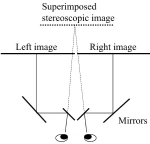
One of the solutions to this problem is to use the 4-mirror stereoscope. This 4-mirror stereoscope is an easiest way to see stereoscopic images. But this paper describes another T. Ohara and K. Sakamoto are with Konan University, 8-9-1 Okamoto, Higashinada, Kobe 658-8501, Japan (e-mail: [email protected]).
S. Nomura is with Nagaoka University of Technology, 1603-1 Kamitomioka, Nagaoka 940-2188, Japan
T. Hirotomi, K. Shiwaku and M. Hirakawa are with Shimane University, 1060 Nishikawatsu-cho, Matsue, Shimane 690-8504, Japan
solution.
We developed the 3D adapter using an optical grating film for stereoscopic viewing. The principle is very simple. The optical grating film shifts both left and right images to the same position. The observer watches overlapped stereoscopic images for left and right eyes. But it is possible to separate left and right images when the observer wears polarizer glasses. This optical grating film is thin and works as a prism. The optical film appropriately locates apart from the display panel so that stereoscopic left and right images are overlapped.
[image:1.595.306.548.458.585.2]The prototype stereoscopic display consists of a commercial 7 inch LCD panel. The screen size of an observed image is 55x70 mm because of dividing a screen in half. We attached a quasi 1/2 wave plate to the half region on the screen. Hence the left image has vertical polarization and the right image has horizontal polarization, for example, because the LCD panel has unidirectional polarization. When the observer wears the polarized glasses, left and right images are separated and stereoscopic 3D images can be observed.
Fig. 1 3D TV broadcast
II. MOTIVATIONS
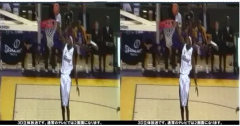
Nippon BS Broadcasting Corporation (BS11 digital) started the BS11 3D television programming in 2007. To watch this program, we need a special TV display which can decode the BS11 3D broadcast signal format. In case of a conventional TV monitor, we observe a side-by-side stereoscopic image as shown in Fig. 1. If the screen is divided in half, it enables us to display left and right stereoscopic images in the same size. A liquid crystal display (LCD) recently comes into common use. An LCD screen has the characteristic of polarization. As shown in Fig. 2, the left and right regions provide the stereoscopic images for left and
Stereoscopic 3D Display System
Using Commercial DIY Goods
right eyes. For example, when the 1/2 wave plate is attached to the right region, the observer, who wears the polarized glasses, can view the separated left and right stereoscopic images. However both stereoscopic images are not in the same position because the center of left and right regions has an interval, then it is difficult for the observer to view the 3D image by the stereoviewing. If the display unit emits orthogonal polarized rays, e.g., vertical polarized left and horizontal right images, and overcomes the image position problem, we can enjoy 3D TV programs using any monitor.
Left
image Right
image Polarizer
[image:2.595.325.532.56.183.2]Polarized glasses
Fig. 2 Stereoscope using polarized glasses (parallel viewing)
III. CONVENTIONAL 3DVISION SYSTEMS
A. Mirror stereoscope
A stereoscope is a device for viewing parallax images, which contain two separate images to create the illusion of a three-dimensional image. Wheatstone's best known contributions to optics are his works on stereoscopy. In 1838 Wheatstone presented a paper whereby he describes the stereoscope as shown in Fig. 3. This principle of stereoscopy was based on the study of Euclid who understood that each eye sees a slightly different view. Wheatstone showed that our impression of solidity is gained by the combination in the mind of two separate pictures of an object taken by both of our eyes from different points of view. Thus, in the stereoscope, as each eye sees a different image, the effect of depth is achieved in the central image of the three. It is impossible for Wheatstone's stereoscope to display 3D image using the stereo pairs that contain two separate images that are printed side-by-side. When these stereo pairs are viewed directly, the observer is required to force their eyes either to cross, or to diverge, so that the two images appear to be three. As shown in Fig. 4, one of the solutions to this problem is to use the 4-mirror stereoscope. This stereoscope is made up by four mirrors. This viewing method uses a mirror placed in front of the monitor to achieve the stereovision effect. The left image and right images are placed side-by-side within a window on the monitor. The mirror allows only the left image to reach the left eye and the right image to reach the right eye. This 4-mirror stereoscope is an easiest way to see stereoscopic images. However, this method has two demerits. The number of viewers is only one person. The other is that the observer needs to peep through the window aperture of restricted viewing position for perceiving the stereoscopic image. To overcome these problems, this paper describes
[image:2.595.85.254.193.304.2]another solution.
Fig. 3 Wheatstone's stereoscope
Mirrors
Left image Right image
Superimposed stereoscopic image
Fig. 4 Four mirror stereoscope
Fig. 5 Stereo viewer
A stereoscope is afterwards improved by dispensing with the mirrors and inserting the lens. Each image is focused by a separate lens, and the two lenses are inclined so as to shift the images toward each other and thus ensure the visual blending of the two images into one three-dimensional image. Fig. 5 shows a commercial viewer which sales to kids.
B. Glasses 3D using side-by-side images
A liquid crystal display recently comes into common use. When the screen is divided in half, it can display two stereoscopic images in the same size. As shown in Fig. 2, the left and right regions provide the stereoscopic images for left and right eyes. An LCD screen has the characteristic of polarization. For example, when the 1/2 wave plate is attached to the right region, the observer, who wears the polarized glasses, can view the separated left and right stereoscopic images.
[image:2.595.351.501.227.371.2] [image:2.595.306.549.406.517.2]computer screen into a 3D display[4]. The cellophane wrap can rotate the polarization of light such as the 1/2 wave plate. Half the screen is covered with the cellophane to change its polarization. Thus the screen of an LCD is divided in half, with each side portraying slightly different images. When an observer uses a pair of glasses that are differently polarized, the right eye can see light coming from the left half of the screen only, and the left eye can see light from the right half of the screen only as shown in Fig. 6.
In these methods, both stereoscopic images are not in the same position because both centers of left and right regions have an interval. The observers are required to force their eyes either to cross, or to diverge, to perceive a 3D image and thus it is difficult for the observer to view the 3D image by the stereoviewing.
Left
image Right
image Polarizer
[image:3.595.322.527.169.650.2]Polarized glasses 1/2 wave plate
Fig. 6 Stereoscope using polarized glasses (cross-eyed viewing)
Polarizer A
Input Output
Vertically Polarized Light Wave
(a) Vertical
Polarizer B
Input Vertically Polarized Light Wave
(b) Horizontal Fig. 7 Polarizer
IV. POLARIZATION CONTROL TECHNIQUE
A. Polarizer
There are two types of polarizing filters, polarizers for short: linear and circular. Fig. 7 shows the basic concept of polarization using the linear polarizer. In this example, the linearly polarized incident light is vibrating vertically before encountering the polarizer, a filter containing long-chain polymer molecules that are oriented in a single direction. Only the incident light that is vibrating parallel to the polarization direction is allowed to pass. Therefore, since polarizer A is oriented vertically, it only permits the vertical waves in the incident beam to pass. However, the vertically polarized waves are subsequently blocked by polarizer B because it is oriented horizontally and absorbs all of the waves that reach it due to their vertical orientation.
B. 1/2 Wave Plate
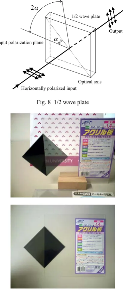
The 1/2(half) wave plate can be used to rotate the polarization state of a plane polarized light as shown in Fig. 8. Suppose a plane-polarized wave is normally incident on a wave plate, and the plane of polarization is at an angle α with respect to the fast axis, as shown. After passing through the plate, the original plane wave has been rotated through an angle 2α. Therefore, the incident light is horizontally polarized wave at 45 degrees with respect to the axis, the output wave is vibrating vertically.
Input polarization plane
1/2 wave plate
α
2αOptical axis Horizontally polarized input
Output
Fig. 8 1/2 wave plate
Fig. 9 Quasi-1/2 wave plate (acrylic resin plate)
C. Quasi 1/2 Wave Plate
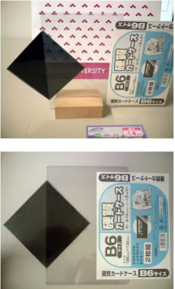
[image:3.595.76.275.241.389.2]the largest franchise of 100-yen shops in Japan. Fig. 9 shows an acrylic resin plate which is sandwiched by two polarizers. As the plate rotates the direction of polarization, a part of the sandwiched plate passes the light on condition both polarizers are orthogonal and blocks the ray in case of the same direction of polarizers. Meanwhile piled two card cases, as double layer is just good, also function as the 1/2 wave plate as shown in Fig. 10. Thus it turned out that some Daiso’s plastic materials work as the 1/2 wave plate.
[image:4.595.310.543.192.250.2]Fig. 10 Quasi-1/2 wave plate (card case)
Fig. 11 Doubling phenomenon
V. 3DADAPTER USING OPTICAL GRATING FILM
A. Motivations
The authors found an interesting material at Tokyu Hands in Shinjuku, Tokyo, Japan. Tokyu Hands is one of the more interesting Do-It-Yourself type stores in Japan. There are many interesting gadgets, gifts, hobby or craft items you might want. The item, which we found, is the optical film and it is named “SOLF”. The SOLF optical sheet is a flexible
film with prisms designed to transport and diffuse the light. This sheet has interesting characteristics as follows; the prismatic phenomenon is observed and the doubling can be visible through the sheet like the Calcite. This doubling phenomenon occurs because the prism sheet diffracts two beams. These beams are called as the first order diffracted beam and the second order diffracted beam. Fig. 11 shows the doubling phenomenon. This interesting phenomenon reminds us of method to superimpose left and right stereoscopic images.
90deg
457μm 178μm
Fig 12 Structure of optical grating sheet
Grating sheet Virtual images Real image plane
(a) Superimpose images
Grating sheet Virtual images Left image Right image
Mask
Polarized glasses
[image:4.595.344.507.290.594.2](b) Stereo viewing
Fig. 13 Overlapping left and right images
B. Superimpose stereoscopic images
[image:4.595.68.269.500.635.2]eyes. But it is possible to separate left and right images when the observer wears polarized glasses. This optical grating film is thin and works as a prism. The optical film appropriately locates apart from the display panel so that stereoscopic left and right images are overlapped. As shown in Fig 13(b), the vertically oriented polarizer is attached on the left half of an image plane. Then an image for the left eye has vertically oriented polarization. Meanwhile, a right eye image has horizontally polarization because the right side of an image plane is covered with a horizontally oriented polarizer. The orthogonal polarized stereoscopic images are overlapped on the same plane. If the observer wears the polarized glasses, he can perceive the left image only by a left eye and the right image by a right eye. Therefore, the observers, who wear the glasses, can view the 3D images by the binocular stereo viewing.
Fig 14: Appearance of prototype 3D display & adapter
(a) desktop screen
(b) overlapped image through grating film Fig. 15 Desktop screen of laptop computer
C. Experiments
Our trial stereoscopic 3D display consists of the commercial 5.4 inch display panel. The screen size of an observed image is 55x70 mm because of dividing a screen in half. We attached the polarizers to the half regions on the image plane. Hence the left image has vertical polarization and the right image has horizontal polarization, for example. When the observer wears the polarized glasses, left and right images are separated and stereoscopic 3D images can be observed. Fig. 14 shows the appearance of developed 3D display using our proposed 3D adapter.
D. Trial 3D display system using laptop computer
Fig. 15 shows the prototype display using a commercial laptop computer. The size of an LCD display is 12.1 inch. This LCD screen is divided in half to display a left image for the left eye and a right image for the right eye as shown in Fig. 15(a). Though the LCD panel is utilized as the displaying plane of side-by-side stereoscopic images, stereoscopic left and right images are overlapped by a grating film. This grating film plate is positioned 70mm apart from the display panel. The observer perceives an overlapped image through the grating film as shown in Fig. 15(b). If the observers wear the polarized glasses, they can view the 3D images by the binocular stereo viewing.
VI. CURRENT WORKING MODEL
We have developed the prototype display using a commercial portable DVD player. This player has a 7inch LCD panel which is utilized as the displaying plane of side-by-side stereoscopic images. The screen of an LCD is divided in half to display a left image for the left eye and a right image for the right eye. The LCD screens, which emit polarized light, light oscillating in a fixed direction. As quasi-wave plate is attached, the polarization direction of a right half screen is rotated in 90-degree angles so as to emit polarized light with orthogonal oriented polarizations. The grating film plate is positioned 50mm apart from the display panel so that stereoscopic left and right images are overlapped. The observer perceives an overlapped image through the grating film as shown in Fig. 16. As the observers wear the polarized glasses, they can view the 3D images by the binocular stereo viewing.
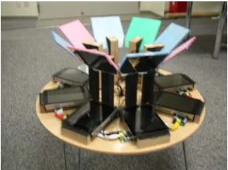
VII. 360DEGREES VIEWING SYSTEM
[image:5.595.88.249.429.722.2]tabletop display can provide different images to two users surrounding the system utilizing the image splitting technologies for displaying a stereoscopic 3D image. But screens on the monitor cannot be viewed correctly by all users from any direction. Thus, conventional display systems enable users not to do collaborative tasks on the round table. To solve this problem, we developed the 360 degree viewing system.
Fig. 16 Viewing screen of 3D display
Mirror image Mirrors
LCD displays Shade
Fig. 17 Optical layout of 360 degrees display This newly developed 360 degree viewing system has eight pairs of an LCD display and a conventional mirror. The principle is very simple. Mirrors are placed with inclined at 45 deg to horizontal as shown in Fig. 17. Since the mirrors are aligned in a circle, mirror images of the displays are generated with floating in the center of a round table. Then the observer can view the monitor screen at any position surrounding the round table as shown in Fig. 18. The size of mirror restricts a viewing zone of a virtual mirror display image. The observer only views the image screen at the front of his face and thus all observers can perceive the one screen
from any direction surrounding the round table.
[image:6.595.344.510.123.247.2]The result of test running is very good. The eight direction virtual image screen planes enable users to be viewed from any direction. It is possible to use this display system for doing collaborative tasks on the round table.
Fig. 18 360 degrees viewing display system(KNX-40)
VIII. CONCLUSION
The authors have researched spatial imaging technology and have ever proposed new techniques of 3D display systems using polarized glasses and liquid crystal shutter glasses, an image splitter such as the parallax barrier or the lenticular screen and holographic optical elements. In this paper, we describe the method of superimposing stereoscopic left and right images for viewing 3D images. We developed a 3D adapter for easy 3D image viewing. Our 3D adapter utilizes the special optical film; an optical grating sheet named “SOLF”. This SOLF sheet is a commercial item and has interesting characteristic for displaying a 3D image. The SOLF optical grating shifts the image plane to both left and right sides. As a result, this grating sheet can overlap both left and right stereoscopic images on the same plane. The polarization characteristics of overlapped stereoscopic images enable the observers to perceive 3D images if they wear the polarized glasses. The 3D adapter is attached to the commercial LCD display, for example, this attachment provides us the low-price 3D viewing system.
ACKNOWLEDGMENT
This research is partially supported by “Grant-in-Aid for Young Scientists(B)” #20700112 and “Scientific Research (C) (General)” #20500481 from Ministry of Education, Culture, Sports, Science and Technology Japan(MEXT) and also by MEXT ORC (2004-2008).
REFERENCES
[1] K. Sakamoto, M. Takaki, M. Nishida, “Parallax Barrier 3D Reflection Display Using Holographic Screen”, Proc. of 12th International Display Workshops, pp.1769-1772, 2005
[2] K. Sakamoto, R. Kimura, M. Takaki, “Elimination of Pseudoscopic Region of Parallax Barrier 3D Display”, Proc. of 11th International Display Workshops, pp. 1497-1498, 2004
[3] K. Sakamoto, R. Kimura, M. Takaki, “Parallax barrier stereoscopic 3D display using polarizer slit”, Proc. of 10th International Conference on Virtual Systems and Multimedia, pp. 128-133, 2004