The Behaviour of Vertical Bell Laboratories Layered
Space-Time Algorithm Combined with Multiuser Detection
Schemes in Wireless Communication System
Ayodeji James Bamisaye1*, Olugbenga Kayode Ogidan 2, Babatope Osalope1
1
Department of Switch Technology, Starcomms Telecommunications, Lagos, Nigeria
2
Information Communications Unit, Ondo State University of Science and Technology, Okitipupa, Nigeria
E-mail: [email protected], [email protected], [email protected] Received November 4, 2010; revised December 5, 2010; accepted January 7, 2011
Abstract
This paper provides the performance analysis of multiuser Vertical Bell Laboratories Layered Space-Time (V-BLAST) system receiver structures for Multiple-input Multiple-Output (MIMO) channel at a base station with assumption of perfect channel estimation and perfect timing delay estimation. In MIMO channels the receivers such as decorrelator, Minimum Mean Square Error (MMSE) and Multistage Parallel Interference
Cancellation (MPIC) receiver outperform the conventional receiver. Withal, since the multiple antenna in-terference led to a strong impact on the performance degradation of a multistage inin-terference cancellation receiver, the performance of MPIC receiver was highly degraded based on system loading.
Keywords:CDMA, Multiple-Input Multiple-Output (MIMO) Channel, Multiuser Detection, Vertical Bell
Laboratories Layered Space-Time (V-BLAST)
1. Introduction
Several techniques are used in wireless communication system for sharing available spectrum resources. These techniques include: frequency division multiple access (FDMA), time division multiple access (TDMA) and code division multiple access (CDMA). (FDMA) assign different frequency to each user, TDMA), assigns dif-ferent time slots to users. However, the CDMA tech-nique shares the entire bandwidth by distinguishing sig-nals with a unique signature for each user. A promising technique to achieve improved capacity for CDMA is multi-user detection [1].
Recent research on wireless communication systems has shown that using multiple antennas at both transmit-ter and receiver offers the possibility of communications at higher data rates compared to single antenna systems [2,3]. Multi input and multi output (MIMO) system has proved in the recent past to provide very high capacity without any increase in the transmission bandwidth and power. The information-theoretic capacity of these multiple- input multiple-output channels was shown to grow line-arly with smaller numbers of transmit and receive anten-nas in rich scattering environments, and at sufficiently
high signal-to-noise (SNR) ratios [4,5].
The performance of multiuser detection along a MIMO downlink system is presented in [6]. A system to enhance signal-to-noise plus noise ratio for Multiple-Input Multiple- Output Code Division Multiple Access (MIMO CDMA) communications in the downlink for frequency-selective fading environments is considered in [7]. The performance of the V-BLAST algorithm combined with multi-user de-tection in downlink system is evaluated in [8].
because of the near-far problem. To ameliorate this pro- blem stringent power control is required in current CDMA system designs. Thus, CDMA performance can be greatly enhanced by multiuser receivers which com-pensate for MAI. One of the first investigations into mul-tiuser reception of CDMA signals was presented in [9].
In this paper, we focus on the V-BLAST system com-bined with multiuser detection schemes without channel coding. The structure of a downlink system is much sim-pler since the MIMO channel is shared to all users. In this downlink system, we can recover all users’ signals by applying various multiuser diction schemes only after equalizing the shared channel. However, for the reverse link, the structure of receivers is more complicated since the channels vary between users [10]. This paper is ar-ranged as follows. Section 2 introduces the system model, Section 3 provides linear and non-linear receiver struc-tures and formulates a detecting algorithm. Simulation results are presented and analyzed in Section 4. Eventu-ally conclusions are drawn in Section 5.
2. System Model
The received baseband signal from user k is defined as a
binary phase modulated waveform:
jkk k k k
s t P a t b t e (1)
jkk k k k k k k
s t P a t b t e (2)
Where k is the kth user's received signal power, k
and k are the spreading and data waveforms
respec-tively (we assume rectangular pulses for both), That is,
kis made to demultiplex input data stream k. This
demultiplexing is the encoding scheme for the V-BLAST at the transmitter and k
P a
b
a b
is the received phase of the kth
user relative to some reference phase. k is the time
delay that models the asynchronous nature of uplink tem which needs not to be considered in down link sys-tem. Due to the asynchronous nature of the system up-link, the received signal is:
1
k k
k k
k
r t
H s t n t (3)k
H represents channel matrix for MIMO channel fad-ing affectfad-ing the user with size T R whose
ele-ment , is the complex fading coefficient for the path from transmit antenna j to receive antenna i. We assume
a single noise source from a common front end. The set of sufficient statistics can be shown to be a set of matched filter outputs where the filters are matched to each user’s spreading code. In terms of the complex en-velope, the vector of sufficient statistics is:
th
k n n
k i j
h
y
cos Θ sin
I Q
y y y
where the ith matched filter output of the kth user is
th
(4)
e
i1
Kkth element of the vector y, Θ is ab b
KN KN diago ts ,
nal matrix where the diag nalo ele-men j jare the phases of the ith bit of the kth user and
1
Kj i k, K is the number of users in the system,
b
KN si
is the num derat
ber of bits in the sequence under con-ion and the in-phase and quadrature components are defined as:
yI
1 1
k
k
iT
k k
i K k i T rI t a t dt
(5)and
(6)
where
1 1
k
k
iT
k k
i K k i T
yQ rQ t a t dt
Re
,
[
]rI t r t rQ t Im r t
and k is the relative delay of the kth user.tor form like: Where the received signal is a vec
[ 1
2 nR
]Tr t r t r t r t (7)
The superscripts of elements of the re ve
ceived signal ctor represent the th
R
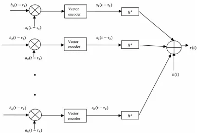
n receive antennas. These fading coefficients are modeled as an independent complex Gaussian random variable with zero mean and variance 0.5 per dimension. Figure 1 illustrates the system.
3. Multiuser Receivers
3.1. Conventional Receiver
The receiver structure is made up of a matched filter bank at each antenna point followed by the V-BLAST decoding block. The outputs of the matched filter banks are rearranged in the form of vector for each corre-sponding user. In matrix form we represent the set of matched filter outputs as:
cos Θ
I I
y RW bn (8)
and
sin ΘQ Q
y RW bn (9)
where R is a KNbKNb matrix
0 1 0
1 0 1
0 1 0
1
0 0 1
H H H
R H H
H
H H
0
H H
0
The (k, l)th element of the KK matrix H(i) is defined
by
(10)
T is the symbol duration, W is a
:
,
k l k k l l
h i a t a t iT dt
b b
eceived en
matrix of the square root of user r ergies de-fined similar to Θ,b is a KNb length vector with the
1
j i Kkth lement l to the ith data symbol
nd e a
equa
of the kth user, nI and nQare vectors of colored
noise samples at the m tched filter outputs. If the users are numbered such that 1 2 .
a
K
then H(l)will be
an upper triangular matr long the diagonal,
( 1) T 1
H H and
ix with zeros a
0 1
H i i . Nf is the
tive s number
of users loaded in the system.
i
f is the
number of consecu ymbols and K is the total
f
KN length vector for
, 1j j l l
nipulated by the
( H )
m of al
, 2, ,b
k k k
H l f users’ data (12) V-BLAST (13) symb mi
fThe statistics are m
o
trix
ts by
ols trans d over the MIMO channel described in Equation (11). Each element is expressed in Equation (12).
T n i k tte 1 j l h
din , aG H
k i N
coding algorithm after the matched filter operation. Here, the operator Gk is defined for convenience as the V-BLAST dec g processing with the nulling matrix
,
k
G which represents the pseudo-inverse channel
ma-of th
k user. The pseudo-inverse channel matrix is
represen : 1 k 1 2 2 n d k k G H ps n m ating Receiver he deci k H -inv k atrix co sion m k el to th
a linear tra
H
(14)
eudo erse chann matrix for
ntributed e
trans-etric is ns- Equation (13)
the ZF nu
k G
Since the co mi
3.2. Decorrel
In a linear detector, t is a
rrelatio
lling criterion and Equation (14) is for the MMSE nulling criterion .This operation cancels the mul-tiple antenna or spatial interference caused by the V-BLAST decoding algorithm in the manner of parallel interference cancellation or serial interference cancella-tion. Therefore, the recovered symbols are represented by:
1 2 nR T
1, 2 ,bk y yk yk k K (15)
tted symbols even in V-BLAST, the desired signal within a conventional receiver cannot avoid the interfer-ence from other user’s signals especially in an asyn-chronous system.
formation of the sufficient statistics that performs
inter-ference cancellation by linear transformation for finding the decision metric i.e.
[ Icos Θ Qsin Θ]
sgn Ty Ty
d (16)
The decorrelator is a linear detector where TR1. The decorrelator removes the correlation between the elements of y [10].
1
[ ]
sgn Wb R n
d (17) This transformation is derived from the maximization of the likelihood function or equivalently the minimiza-tion of
T 1
[2].yRb R yRb
The decorrelating receiver is a linear detector. Elimi-nating the interference from undesired signals at the first stage using: 1 2 ] [ , i i R
Ty i n
d (18) The linear transformation, , is obtained from the maximization of the likelihood function or equiva-lently the minimization of
1 T R
1Λ Θ (YRΘ)TR (YRΘ)
Θ
where y represents the output of matched filter and is estimated signal.
1 1, 2
i i
R
R y i n
d (20)
1 1, 2 .
i
R
Wb R n i n
(21) At the second stage, after rearranging the decorrelated signals, the V-BLAST decoding algorithm is applied to the signal where the spatial interference of unde-sired signals is reduced and the symbols are decided as follows:
i
d
1 2 R
1, 2 ,k
n
k k k k
T
G
b d d d k K (22)
3.3. Minimum Mean Square Error (MMSE) Receiver
A similar receiver structure can be obtained if the trans-formation is sought which minimizes the mean square error of the bit estimate,
T
b y b y
T R1 . In this case the linear transformation used in [10]
1 sgn Wb R n
d is replaced by
2 0 2 2 N T R W .
The performance of the MMSE detector approaches the decorrelator as 0 . As 0 grows large, T ap- proaches an identity matrix scaled by
0
N N
0 2
N and is thus reduced to the conventional receiver. Thus, the MMSE detector seeks to strike a balance between removing the interference and not enhancing the noise. At low
T1 1 2 1 1 2 2 2 1 2
i i i i i i i
k k Nf Nf k N
f fi
1 f f f f f f i i
f f f (11)
1i 2i 1 1i 2 2i 2 ki 1i Nf 2i Nf ki Nf ]
[ 1 d d d d d d d T (19)
Figure 1. Model of multiuser v-blast system on mimo channel.
0
b
E N the MMSE receiver
lator, while the decorrelator has superior BER per for-mance
will outperform the décor re
at high Eb N0. Due to the residual interference this transformation results in an estimate which is biased, and its performa dependent on the power levels of the interferers.
nce is
1 0
i i
2 1, 2 .
2 R
N
d R y i n
W
(23) As a spatial interference cancellation
BLAST decoding block is the same as for the decorrela-to
3.4. Multistage Parallel Interference Cancellation (MPIC)
Mul vers which have multiple
ation and cancellation. This cancellation approach was developed in [11,12]. In [11]
K
(25)
step, the V-
r by:
1 2( R] 1, 2 ,
k
n T
k k k k
b d d d k K (24)
G
tistage receivers are recei
stages of interference estim
it was suggested that each user's signal could be itera-tively estimated in parallel. The estimates for each user can then be used to reduce the interference by subtracting the estimate of each interferer from the desired user's signal. The entire process can be repeated for several stages. At each stage, better estimates of each user are produced, allowing more effective interference cancella-tion. In this paper we assume the use of matched filters at each stage for estimation. This allows a single estimate (the matched filter output) to be used for both the data symbol and the channel gain and alleviates the need for any outside power estimates. Mathematically we can represent the decision metric for an S-stage parallel can-cellation scheme as:
1 2 R S k
T n
S S
k G k
b y y
k yk k 1, 2 ,
where
( )
1
1
( ) , 1, 2 , 1, 2 ,
k
K
iT i s
i s
k i T k k k R
y t a t dt i n k
T
r K (26)
( ) ( ) 1 ( )
i s i s
k j
j k
t r t y a tj j
r
for the ith bit of the kth user and
(27)
1
,j i Kk rki s( )
t is the kth user's in-phase after s-1 stages of cancellation.
,( ) ( ) ( 1) , 1, 2 . , 1, 2 ..,
i s i s
j j
k j R
j k
y r t y t a
The superscript i represents the receive antenna
num-er, k is the user number, represents the S-
t b s
,i s k
r t
ding se age signal of the th
k user at antenna i after
cancella-tion, ak represents the sprea quence of the th
k user, and k repres ts the estimated time delay of the
th
k u . The operator Gk represents the V-BLA decoding cessing. A bias reduction technique for
tistage interference ca llation is verified in [1]. The bias increases linearly with system loading such that the bias influences the decision statistics in the first stage of multiple access interference cancellation. The effect of bias is mitigated for subsequent stages. To reduce the effect of bias, a partial cancellation factor ( )S
C is em-ployed. This factor varies at every stage in the range 0, 1. The partial-cancellation factor ( )S
C of 0. second stage gives good performance improvement [8]. The mathematical form of cancellatio ith the partial can-cellation factor is formulated by Equation (29) as below.
4. Simulation Results and Analysis
enser ST
pro
mul nce
5 at
n w
successive ed. Perfect
cancellation factors at second The ZF nulling V-BLAST algorithm based on
spatial interference cancellation is employ
[image:5.595.312.534.240.422.2] [image:5.595.311.535.468.649.2]power control, perfect channel estimation and time delay estimation are assumed. Rayleigh flat fading channel is considered. We define one frame as one packet of 20 symbols. The channel coefficients are modeled with an independent zero mean complex Gaussian random vari-able with variance 0.5 per dimension. The channel coef-ficients are constant during one frame transmission. Gold sequences with 31 processing gain are utilized. Each chip of the spreading sequences is sampled at 5 samples/chip. Timing delays are generated randomly to realize an asynchronous model.
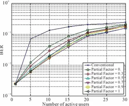
Figure 2 depicts the performance of three-stage PIC with the various
partial-stage. For the lightly loaded system, partial cancellation factors of 0.7 and 0.9 give good reduction of the multiple access interference at the second stage. However, par-tial-cancellation factors of 0.7 and 0.5 mitigate the effect of bias relatively well for a highly loaded system. By comparison, the partial-cancellation factor 0.7 can be considered as the best choice at flat fading MIMO chan-nel. The capacity curves for Eb N020dB and proc-essing gain N = 31 are shown in Figure 3.
It was observed that the perf e decorrela-tor, MMSE detector and two-stage PIC c bined with de
ormance of th om
to the conventional receiv
the three-stage (parallel interference cancellation) PIC
ow the number of stages affects the perform-an
correlator at first stage are equivalent. More so, they exhibit enormous performance improvement compared
er. However, the behaviour of
receiver, that is a non-linear interference cancellation receiver, gradually degrades as the number of active us-ers increase even though it outperforms the conventional receiver.
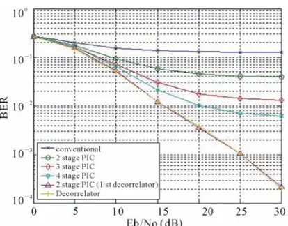
Figure 4 illustrates results for a system with 10 users, showing h
ce improvement for multistage PIC. It shows how the number of stages affects the performance improvement of multistage PIC. It was observed that the performance of MPIC is improved as the number of stages increases.
Figure 2. BER versus number of active users as influenced by partial-cancellation factor for MPIC in Flat Fading MIMO channels.
Figure 3. BER versus number of active users with perfect channel estimation in Flat Fading MIMO channels.
, 1, 2 . , 1, 2 ..,i n k K
, i 1
i s S s
rk t r t C
yj aj t j R (29)j k
Figure 4. BER versus Eb/No with perfect channel estima-tion under Flat fading MIMO channels.
s the decorrelator and the MMSE receiver since the multiple antenna inter-fe
igated the behaviour of V-BLAST iver structure of multiuser detectors. he performance of MPIC receivers with various
par-[1] S. Verdu, “Multiuser Detection,” Cambridge University ge, 1998.
[2] N. Prabagarane, M. Ramakris and B. Jalaja, “Performanc
Receivers for Coded Signals in MIMO Channels,” 4th
ser Detection for 4G
Mo-d CDMA Mobile System,” Wireless Sensor
Net-ence
Cancel-logy Conference, Vol. 1, Spring 2002, pp. 45-
sactions on Wireless Communications, Vol. 2, No. 2,
However, the MPIC performance does not equal the performance of linear detectors such a
lat
rence prevents the MPIC receivers from cancelling out the multiple access interference appropriately. We rec-ognize that the multiple antenna interference affects the performance of the non-linear multiple access interfer-ence cancellation receiver. Therefore, the MPIC receiv-ers are not suitable without a channel coding scheme for MIMO channels.
5. Conclusions
This paper invest combined with rece T
tial-cancellation factors was verified. All receivers such as the decorrelator, MMSE and MPIC achieve the tre-mendous performance improvement compared to the conventional receiver that does not eliminate multiple access interference. However, the MPIC receiver, which is one of the nonlinear detectors, over the MIMO chan-nels, is not robust to interference from multiple antennas that obstruct cancellation at each stage, whereas linear detectors are not as severely affected by multiple antenna interference.
6. References
Press, Cambrid
hnan, T. Divya, M. Thomas e Evaluation of Multi Stage
IEEE WiCOM, October 2008.
[3] V. Arun, A. S. S. Vasan and L. Krishnan, “Investigations on the Performance of MIMO Assisted Multi Carrier DS/CDMA System with Multiu
bile Communications,” Project Report, SSN Institutions, 2009.
[4] A. J. Bamisaye and M. O. Kolawole, “Evaluation of Downlink Performance of a Multiple-Cell, Rake Receiver Assiste
work, Vol. 2, No. 1, 2010, pp. 1-6.
[5] A. J. Bamisaye and M. O. Kolawole, “Uplink Perform-ance Evaluation of CDMA Communication System with Rake Receiver and Multiple Access Interfer
ion,” International Journal of Communications, Net-works and System Science, Vol. 3, No. 6, 2010, pp. 540-547.
[6] H. Dai and A. F. Molisch, “Multiuser Detection for In-terference-Limited MIMO Systems,” 55th IEEE Vehicu-lar Techno
49.
[7] R. L. Choi, R. D. Murch and K. B. Letaief, “MIMO CDMA Antenna System for SINR Enhancement,” IEEE Tran
March 2003, pp. 240-249.
doi:10.1109/TWC.2003.808961
[8] D. Samardzija, P. Wolniansky and J. Ling, “Performance Evaluation of the VBLAST
tems,” IEEE Vehicular Technolo
Algorithm in W-CDMA Sys-gy Conference, Vol. 2,
, Vol. AES-15, No. 1, January Fall 2001, pp. 723-727.
[9] K. S. Schneider, “Optimum Detection of Code Division Multiplexed Signals,” IEEE Transactions on Aerospace and Electronic Systems
1979, pp. 181-185. doi:10.1109/TAES.1979.308816
[10] W. Wu and K. Chen, “Linear Multiuser Detectors for Synchronous CDMA Communication over Rayleigh Fading Channels,” 17thIEEE International Symposium,
. 38, Personal, Indoor and Mobile Radio Communications, PIMRC’96, Vol. 2, October 1996, pp. 578-582.
[11] M. K. Varanasi and B. Aazhang, “Multistage Detection in Asynchronous Code-Division Multiple Access Commu-nications,” IEEE Transaction Communication, Vol April 1990, pp. 509-519. doi:10.1109/26.52662
[12] R. Kohno, H. Imai, M. Hatori and S. Pasupathy, “An Adaptive Canceller of Cochannel Interference for Spread- Spectrum Multiple-Access Communication Networks in a Power Line,” IEEE Journal on Selected Areasin Com-munications,Vol. 8, No. 4, May 1990, pp. 691-699.