EXPLORING ALTERNATE CACHE INDEXING TECHNIQUES
A Thesis by
SANGAM JINDAL
Submitted to the Office of Graduate and Professional Studies of Texas A&M University
in partial fulfillment of the requirements for the degree of MASTER OF SCIENCE
Chair of Committee, Daniel A. Jiménez Committee Members, Paul Gratz
Dilma Da Silva Head of Department, Dilma Da Silva
August 2018
Major Subject: Computer Engineering
ABSTRACT
Cache memory is a bridging component which covers the increasing gap between the speed of a processor and main memory. An excellent performance of the cache is crucial to improve system performance. Conflict misses are one of the critical reasons that limit the cache performance by mapping blocks to the same set which results in the eviction of many blocks. However, many blocks in the cache sets are not mapped, and thus the available space is not efficiently utilized. A direct way to reduce conflict misses is to increase associativity, but this comes with the cost of an increase in the hit time. Another way to reduce conflict misses is to change the cache-indexing scheme and distribute the accesses across all sets.
This thesis focuses on the second way mentioned above and aims to evaluate the impact of the matrix-based indexing scheme on cache performance against the traditional modulus-based index-ing scheme. A correlation between the proposed indexindex-ing scheme and different cache replacement policies is also observed.
The matrix-based indexing scheme yields a geometric mean speedup of 1.2% for SPEC CPU 2017 benchmarks for single core simulations when applied for direct-mapped last level cache. In this case, an improvement of 1.5% and 4% is observed for at least eighteen and seven of SPEC CPU2017 applications respectively. Also, it yields 2% of performance improvement over sixteen SPEC CPU2006 benchmarks. The new indexing scheme correlates well with multiperspective reuse prediction. It is observed that LRU benefits machine learning benchmark by a performance of 5.1%. For multicore simulations, the new indexing scheme does not improve performance significantly. However, this scheme also does not impact the application’s performance negatively.
DEDICATION
To my parents, Rekha and Dinesh Jindal and my brother Shubham, my grandparents: Bimla Devi, Shishpal Jindal, Late Prannath Sharma, Late Vimla Sharma, for their immense love and support.
ACKNOWLEDGMENTS
I am fortunate to work under the supervision of Dr Daniel Jiménez and thankful for his guid-ance while working on this thesis. His expertise, patience, time and constant encouragement held me strong and became a guiding light all the way during this research. I would also like to express my sincere gratitude to the respected committee members, Dr. Dilma Da Silva and Dr. Paul Gratz for their trust and constant support.
I am grateful to the Almighty and to my parents in India, Rekha and Dinesh Jindal, my brother Shubham, my grandparents, Bimla Devi, Shishpal Jindal, Late Prannath Sharma, Late Vimla Sharma for their blessings, and confidence they instilled in me pursue and accomplish my en-deavours in the United States.
I would also like to thank my friends and colleagues who helped me throughout this journey. A huge thanks to my labmate Luna for all her support and suggestions. And to my all labmates Samira and Elba for all their feedback. A special thanks to all my loving friends: Manjunathan, Deeksha, Harish, Selva, Shrija, Rishabh, Nithya, Chandana, Aseem, Ashish, Prateek, Badhri, Vignesh.
Thanks to Mrs Karrie Bourquin and the entire staff at CSE Graduate Office for making this journey possible. Also, I am thankful to the department of Texas A&M High-Performance Re-search Computing for providing the advanced computing resources for this reRe-search.
CONTRIBUTORS AND FUNDING SOURCES
Contributors
This work was supported by a thesis committee consisting of Professor Daniel A. Jiménez and Professor Dilma Da Silva of the Department of Computer Science and Engineering and Professor Paul V. Gratz of the Department of Electrical and Computer Engineering.
The traces and invertible matrices were provided by Professor Daniel A. Jiménez. The simula-tor was provided by Jinchun Kim of the Department of Electrical and Computer Engineering.
All other work conducted for the thesis was completed by the student independently.
Funding Sources
This research was funded in part by NSF grants CCF-1649242 and CCF-1216604/1332598 as well as a generous gift from Intel Labs.
Portions of this research were conducted with the advanced computing resources provided by Texas A&M High Performance Research Computing.
NOMENCLATURE
CPU central processing unit
GPU graphics processing unit
RAM random access memory
DRAM dynamic RAM
SRAM static RAM
RRIP re-reference interval prediction
DRRIP dynamic RRIP
SRRIP static RRIP
BRRIP bimodal RRIP
RRPV re-reference interval prediction
LRU least recently used
PC program counter
SDBP sampling-based dead block prediction
SHIP signature-based hit predictor
LLC last level cache
KPC kill the program counter
KPC-P KPC prefetching algorithm
KPC-R KPC replacement algorithm
EAF evicted address filter
MRP multiperspective reuse prediction
AMI arbitrary modulus indexing
PCM phase change based main memory
RIB random invertible binary matrix
KB kilobytes
AMAT average memory access time
DGH demand global hysteresis
PGH prefetch global hysteresis
DA-AMPM DRAM-aware access map pattern matching
SPEC standard performance evaluation corporation
TACO Texas Architecture and Compiler Optimization
IPC instructions per cycle
MPKI misses per kiloinstruction
PACMan prefetch aware mechanism
TABLE OF CONTENTS
Page
ABSTRACT . . . ii
DEDICATION . . . iii
ACKNOWLEDGMENTS . . . iv
CONTRIBUTORS AND FUNDING SOURCES . . . v
NOMENCLATURE . . . vi
TABLE OF CONTENTS . . . viii
LIST OF FIGURES . . . x
LIST OF TABLES. . . xxii
1. INTRODUCTION . . . 1
1.1 Document Structure . . . 2
2. BACKGROUND & MOTIVATION . . . 3
2.1 Cache organization and Miss Types . . . 3
2.2 Conflict Miss Handling . . . 7
2.3 Indexing schemes . . . 8
2.3.1 Modulus based indexing scheme . . . 8
2.3.2 Matrix based indexing scheme . . . 8
3. RELATED WORK . . . 10
3.1 Re-Reference Interval Prediction . . . 10
3.2 Sampling-Based Dead Block Prediction . . . 11
3.3 Signature-Based Hit Predictor . . . 11
3.4 Evicted Address Filter . . . 12
3.5 Kill the Program Counter . . . 12
3.6 Multiperspective Reuse Prediction . . . 13
3.7 Indexing schemes . . . 14
4. APPROACH . . . 17
4.1.1 Invertible Matrices. . . 17 4.1.2 Algorithm . . . 18 5. METHODOLOGY . . . 22 5.1 Host machine . . . 22 5.2 Benchmarks . . . 22 5.3 Simulator . . . 24 5.4 Experimental Configuration . . . 27 5.5 Performance Evaluation . . . 28 6. RESULTS . . . 30 6.1 Single-Core Results . . . 30
6.1.1 Direct mapped cache . . . 30
6.1.2 Replacement Policy Impact . . . 31
6.1.3 Impact of indexing on different cache levels . . . 32
6.2 Multi-Core Results . . . 33
6.2.1 Direct mapped configuration . . . 33
6.2.2 Impact on different cache levels and Replacement Policies . . . 34
7. CONCLUSIONS AND FUTURE WORK . . . 51
REFERENCES . . . 52
APPENDIX A. RIB MATRICES . . . 57
APPENDIX B. SINGLE-CORE RESULTS . . . 62
LIST OF FIGURES
FIGURE Page
2.1 Cache memory with size SxAssociativityxB Bytes, where S is number of sets and
B is block size (in bytes) . . . 5
2.2 (i) Direct mapped cache, (ii) Set associative cache with associativity 2, (iii) Fully associative cache . . . 6
2.3 (i) Blocks mapped to set whose all lines are already utilized, i.e. conflict misses, (ii) Blocks mapped to unutilized sets, i.e. effect of efficient indexing scheme. . . 7
2.4 Modulus based indexing scheme . . . 8
4.1 reprinted from: Binary arithmetic in Matrix based indexing scheme [1] . . . 18
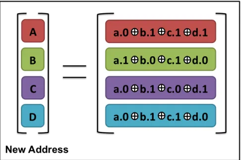
4.2 New Randomized address after Binary arithmetic . . . 19
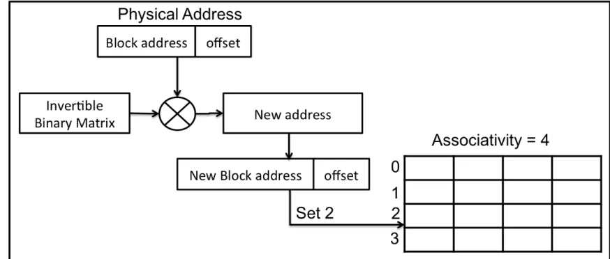
4.3 Matrix based indexing scheme used for 4-way set-associative cache . . . 21
6.1 Y-axis shows the speedup along with confidence intervals showing one standard deviation above and below the mean, when proposed indexing scheme is enable only for mapped LLC over the conventional indexing scheme for direct-mapped LLC. X-axis shows SPEC CPU2006, Cloudsuite and machine learning benchmarks. . . 35
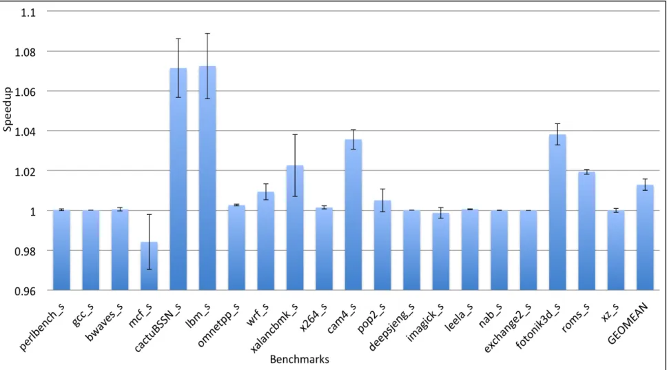
6.2 Y-axis shows the speedup along with confidence intervals showing one standard deviation above and below the mean, when proposed indexing scheme is enable only for mapped LLC over the conventional indexing scheme for direct-mapped LLC. X-axis shows SPEC CPU2017 benchmarks. . . 36
6.3 Y-axis shows the speedup along with confidence intervals showing one standard de-viation above and below the mean, when proposed indexing scheme is enable only for direct-mapped LLC over the conventional indexing scheme for set-associative LLC. X-axis shows SPEC CPU2006, Cloudsuite and machine learning benchmarks. 37 6.4 Y-axis shows the speedup along with confidence intervals showing one standard
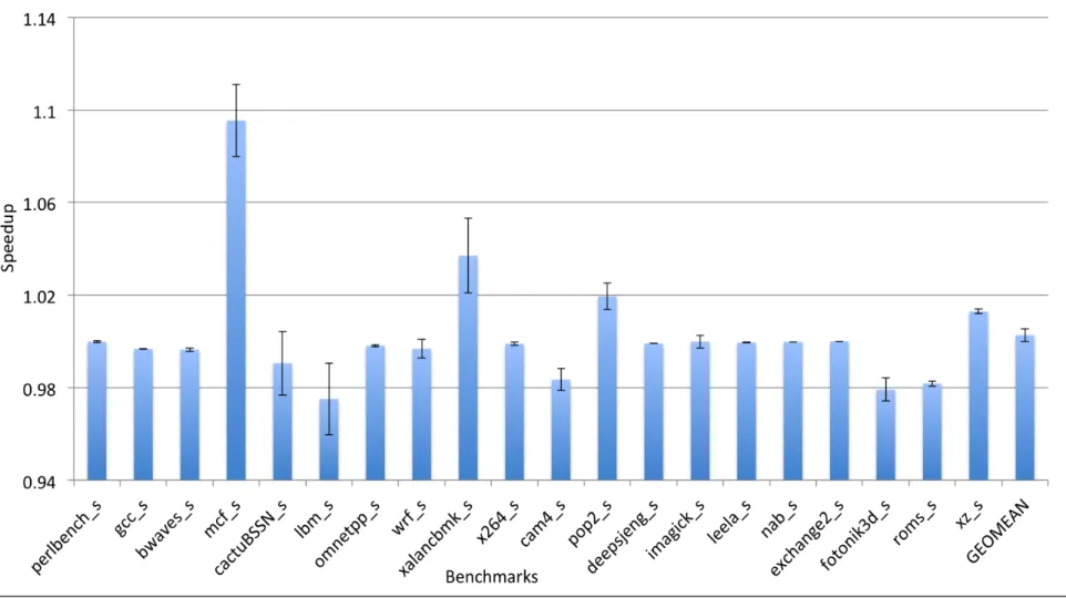
de-viation above and below the mean, when proposed indexing scheme is enable only for direct-mapped LLC over the conventional indexing scheme for set-associative LLC. X-axis shows SPEC CPU2017 benchmarks. . . 38 6.5 Y-axis shows the speedup along with confidence intervals showing one standard
deviation above and below the mean, to compare different replacement policies with proposed indexing scheme enabled only for LLC over the baseline configura-tion i.e. different replacement policies with convenconfigura-tional indexing scheme. X-axis shows SPEC CPU2006, Cloudsuite and machine learning benchmarks. . . 39 6.6 Y-axis shows the speedup along with confidence intervals showing one standard
deviation above and below the mean, to compare different replacement policies with proposed indexing scheme enabled only for LLC over the baseline configura-tion i.e. different replacement policies with convenconfigura-tional indexing scheme. X-axis shows SPEC CPU2017 benchmarks. . . 40 6.7 Y-axis shows the speedup along with confidence intervals showing one standard
deviation above and below the mean, when proposed indexing scheme is enable for both second level and LLC over when new scheme is enable only for LLC. X-axis shows SPEC CPU2006, Cloudsuite and machine learning benchmarks. . . 41 6.8 Y-axis shows the speedup along with confidence intervals showing one standard
deviation above and below the mean, when proposed indexing scheme is enable for both second level and LLC over when new scheme is enable only for LLC. X-axis shows SPEC CPU2017 benchmarks.. . . 42
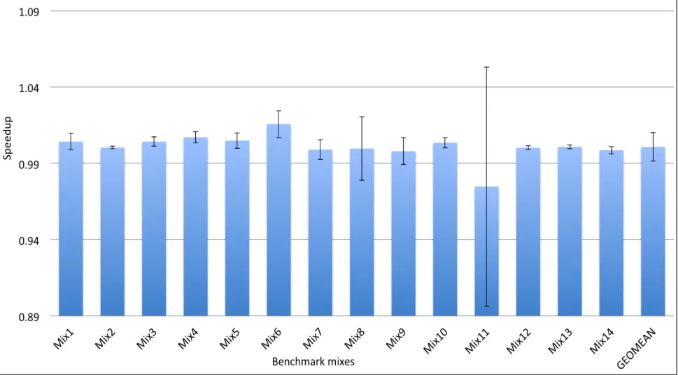
6.9 Y-axis shows the speedup along with confidence intervals showing one standard deviation above and below the mean, when proposed indexing scheme is enable only for mapped LLC over the conventional indexing scheme for direct-mapped LLC. X-axis shows different mixes of SPEC CPU2006, Cloudsuite and machine learning benchmarks. . . 43 6.10 Y-axis shows the speedup along with confidence intervals showing one standard
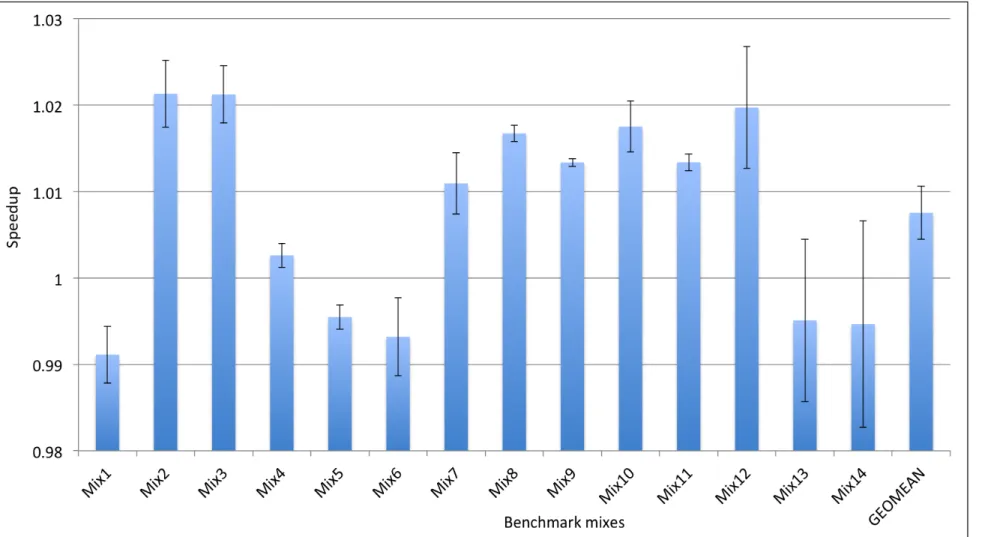
deviation above and below the mean, when proposed indexing scheme is enable only for mapped LLC over the conventional indexing scheme for direct-mapped LLC. X-axis shows different mixes of SPEC CPU2017 benchmarks. . . 44 6.11 Y-axis shows the speedup along with confidence intervals showing one standard
de-viation above and below the mean, when proposed indexing scheme is enable only for direct-mapped LLC over the conventional indexing scheme for set-associative LLC. X-axis shows different mixes of SPEC CPU2006, Cloudsuite and machine learning benchmarks. . . 45 6.12 Y-axis shows the speedup along with confidence intervals showing one standard
de-viation above and below the mean, when proposed indexing scheme is enable only for direct-mapped LLC over the conventional indexing scheme for set-associative LLC. X-axis shows different mixes of SPEC CPU2017 benchmarks.. . . 46 6.13 Y-axis shows the speedup along with confidence intervals showing one standard
deviation above and below the mean, to compare different replacement policies with proposed indexing scheme enabled only for LLC over the baseline configura-tion i.e. different replacement policies with convenconfigura-tional indexing scheme. X-axis shows different mixes of SPEC CPU2006, Cloudsuite and machine learning bench-marks. . . 47
6.14 Y-axis shows the speedup along with confidence intervals showing one standard deviation above and below the mean, to compare different replacement policies with proposed indexing scheme enabled only for LLC over the baseline configura-tion i.e. different replacement policies with convenconfigura-tional indexing scheme. X-axis shows different mixes of SPEC CPU2017 benchmarks. . . 48 6.15 Y-axis shows the speedup along with confidence intervals showing one standard
deviation above and below the mean, when proposed indexing scheme is enable for both second level and LLC over when new scheme is enable only for LLC. X-axis shows different mixes of SPEC CPU2006, Cloudsuite and machine learning benchmarks. . . 49 6.16 Y-axis shows the speedup along with confidence intervals showing one standard
deviation above and below the mean, when proposed indexing scheme is enable for both second level and LLC over when new scheme is enable only for LLC. X-axis shows different mixes of SPEC CPU2017 benchmarks. . . 50 B.1 Y-axis shows the speedup when proposed indexing scheme is enable only for
direct-mapped LLC over the baseline configuration for RIB matrix1. X-axis shows SPEC CPU2006, Cloudsuite and machine learning benchmarks. . . 63 B.2 Y-axis shows the speedup when proposed indexing scheme is enable only for
direct-mapped LLC over the baseline configuration for RIB matrix1. X-axis shows SPEC CPU2017 benchmarks. . . 64 B.3 Y-axis shows the speedup when proposed indexing scheme is enable only for
direct-mapped LLC over the baseline configuration for RIB matrix2. X-axis shows SPEC CPU2006, Cloudsuite and machine learning benchmarks. . . 65 B.4 Y-axis shows the speedup when proposed indexing scheme is enable only for
direct-mapped LLC over the baseline configuration for RIB matrix2. X-axis shows SPEC CPU2017 benchmarks. . . 66
B.5 Y-axis shows the speedup when proposed indexing scheme is enable only for direct-mapped LLC over the baseline configuration for RIB matrix3. X-axis shows SPEC CPU2006, Cloudsuite and machine learning benchmarks. . . 67 B.6 Y-axis shows the speedup when proposed indexing scheme is enable only for
direct-mapped LLC over the baseline configuration for RIB matrix3. X-axis shows SPEC CPU2017 benchmarks. . . 68 B.7 Y-axis shows the speedup when proposed indexing scheme is enable only for
direct-mapped LLC over the baseline configuration for RIB matrix4. X-axis shows SPEC CPU2006, Cloudsuite and machine learning benchmarks. . . 69 B.8 Y-axis shows the speedup when proposed indexing scheme is enable only for
direct-mapped LLC over the baseline configuration for RIB matrix4. X-axis shows SPEC CPU2017 benchmarks. . . 70 B.9 Y-axis shows the speedup when proposed indexing scheme is enable only for
direct-mapped LLC over the baseline configuration for RIB matrix5. X-axis shows SPEC CPU2006, Cloudsuite and machine learning benchmarks. . . 71 B.10 Y-axis shows the speedup when proposed indexing scheme is enable only for
direct-mapped LLC over the baseline configuration for RIB matrix5. X-axis shows SPEC CPU2017 benchmarks. . . 72 B.11 Y-axis shows the speedup when proposed indexing scheme is enable only for
direct-mapped LLC over the baseline configuration for RIB matrix6. X-axis shows SPEC CPU2006, Cloudsuite and machine learning benchmarks. . . 73 B.12 Y-axis shows the speedup when proposed indexing scheme is enable only for
direct-mapped LLC over the baseline configuration for RIB matrix6. X-axis shows SPEC CPU2017 benchmarks. . . 74 B.13 Y-axis shows the speedup when proposed indexing scheme is enable only for
direct-mapped LLC over the baseline configuration for RIB matrix7. X-axis shows SPEC CPU2006, Cloudsuite and machine learning benchmarks. . . 75
B.14 Y-axis shows the speedup when proposed indexing scheme is enable only for direct-mapped LLC over the baseline configuration for RIB matrix7. X-axis shows SPEC CPU2017 benchmarks. . . 76 B.15 Y-axis shows the speedup when proposed indexing scheme is enable only for
direct-mapped LLC over the baseline configuration for RIB matrix8. X-axis shows SPEC CPU2006, Cloudsuite and machine learning benchmarks. . . 77 B.16 Y-axis shows the speedup when proposed indexing scheme is enable only for
direct-mapped LLC over the baseline configuration for RIB matrix8. X-axis shows SPEC CPU2017 benchmarks. . . 78 B.17 Y-axis shows the speedup when proposed indexing scheme is enable only for
direct-mapped LLC over the baseline configuration for RIB matrix9. X-axis shows SPEC CPU2006, Cloudsuite and machine learning benchmarks. . . 79 B.18 Y-axis shows the speedup when proposed indexing scheme is enable only for
direct-mapped LLC over the baseline configuration for RIB matrix9. X-axis shows SPEC CPU2017 benchmarks. . . 80 B.19 Y-axis shows the speedup when proposed indexing scheme is enable only for
direct-mapped LLC over the baseline configuration for RIB matrix10. X-axis shows SPEC CPU2006, Cloudsuite and machine learning benchmarks. . . 81 B.20 Y-axis shows the speedup when proposed indexing scheme is enable only for
direct-mapped LLC over the baseline configuration for RIB matrix10. X-axis shows SPEC CPU2017 benchmarks. . . 82 B.21 Y-axis shows the speedup when proposed indexing scheme is enable for both
sec-ond level and LLC over when new scheme is enable only for LLC for RIB matrix1. X-axis shows different mixes of SPEC CPU2006, Cloudsuite and machine learning benchmarks. . . 83
B.22 Y-axis shows the speedup when proposed indexing scheme is enable only for direct-mapped LLC over the baseline configuration for RIB matrix1. X-axis shows SPEC CPU2017 benchmarks. . . 84 B.23 Y-axis shows the speedup when proposed indexing scheme is enable for both
sec-ond level and LLC over when new scheme is enable only for LLC for RIB matrix2. X-axis shows different mixes of SPEC CPU2006, Cloudsuite and machine learning benchmarks. . . 85 B.24 Y-axis shows the speedup when proposed indexing scheme is enable only for
direct-mapped LLC over the baseline configuration for RIB matrix2. X-axis shows SPEC CPU2017 benchmarks. . . 86 B.25 Y-axis shows the speedup when proposed indexing scheme is enable for both
sec-ond level and LLC over when new scheme is enable only for LLC for RIB matrix3. X-axis shows different mixes of SPEC CPU2006, Cloudsuite and machine learning benchmarks. . . 87 B.26 Y-axis shows the speedup when proposed indexing scheme is enable only for
direct-mapped LLC over the baseline configuration for RIB matrix3. X-axis shows SPEC CPU2017 benchmarks. . . 88 B.27 Y-axis shows the speedup when proposed indexing scheme is enable for both
sec-ond level and LLC over when new scheme is enable only for LLC for RIB matrix4. X-axis shows different mixes of SPEC CPU2006, Cloudsuite and machine learning benchmarks. . . 89 B.28 Y-axis shows the speedup when proposed indexing scheme is enable only for
direct-mapped LLC over the baseline configuration for RIB matrix4. X-axis shows SPEC CPU2017 benchmarks. . . 90
B.29 Y-axis shows the speedup when proposed indexing scheme is enable for both sec-ond level and LLC over when new scheme is enable only for LLC for RIB matrix5. X-axis shows different mixes of SPEC CPU2006, Cloudsuite and machine learning benchmarks. . . 91 B.30 Y-axis shows the speedup when proposed indexing scheme is enable only for
direct-mapped LLC over the baseline configuration for RIB matrix5. X-axis shows SPEC CPU2017 benchmarks. . . 92 B.31 Y-axis shows the speedup when proposed indexing scheme is enable for both
sec-ond level and LLC over when new scheme is enable only for LLC for RIB matrix6. X-axis shows different mixes of SPEC CPU2006, Cloudsuite and machine learning benchmarks. . . 93 B.32 Y-axis shows the speedup when proposed indexing scheme is enable only for
direct-mapped LLC over the baseline configuration for RIB matrix6. X-axis shows SPEC CPU2017 benchmarks. . . 94 B.33 Y-axis shows the speedup when proposed indexing scheme is enable for both
sec-ond level and LLC over when new scheme is enable only for LLC for RIB matrix7. X-axis shows different mixes of SPEC CPU2006, Cloudsuite and machine learning benchmarks. . . 95 B.34 Y-axis shows the speedup when proposed indexing scheme is enable only for
direct-mapped LLC over the baseline configuration for RIB matrix7. X-axis shows SPEC CPU2017 benchmarks. . . 96 B.35 Y-axis shows the speedup when proposed indexing scheme is enable for both
sec-ond level and LLC over when new scheme is enable only for LLC for RIB matrix8. X-axis shows different mixes of SPEC CPU2006, Cloudsuite and machine learning benchmarks. . . 97
B.36 Y-axis shows the speedup when proposed indexing scheme is enable only for direct-mapped LLC over the baseline configuration for RIB matrix8. X-axis shows SPEC CPU2017 benchmarks. . . 98 B.37 Y-axis shows the speedup when proposed indexing scheme is enable for both
sec-ond level and LLC over when new scheme is enable only for LLC for RIB matrix9. X-axis shows different mixes of SPEC CPU2006, Cloudsuite and machine learning benchmarks. . . 99 B.38 Y-axis shows the speedup when proposed indexing scheme is enable only for
direct-mapped LLC over the baseline configuration for RIB matrix9. X-axis shows SPEC CPU2017 benchmarks. . . 100 B.39 Y-axis shows the speedup when proposed indexing scheme is enable for both
sec-ond level and LLC over when new scheme is enable only for LLC for RIB ma-trix10. X-axis shows different mixes of SPEC CPU2006, Cloudsuite and machine learning benchmarks. . . 101 B.40 Y-axis shows the speedup when proposed indexing scheme is enable only for
direct-mapped LLC over the baseline configuration for RIB matrix10. X-axis shows SPEC CPU2017 benchmarks. . . 102 B.41 Y-axis shows the speedup to compare different replacement policies with proposed
indexing scheme enabled only for LLC over the baseline configuration i.e. dif-ferent replacement policies with conventional indexing scheme for RIB matrix3. X-axis shows different mixes of SPEC CPU2006, Cloudsuite and machine learn-ing benchmarks. . . 103 B.42 Y-axis shows the speedup to compare different replacement policies with proposed
indexing scheme enabled only for LLC over the baseline configuration i.e. different replacement policies with conventional indexing scheme for RIB matrix3. X-axis shows different mixes of SPEC CPU2017 benchmarks. . . 104
B.43 Y-axis shows the speedup to compare different replacement policies with proposed indexing scheme enabled only for LLC over the baseline configuration i.e. dif-ferent replacement policies with conventional indexing scheme for RIB matrix4. X-axis shows different mixes of SPEC CPU2006, Cloudsuite and machine learn-ing benchmarks. . . 105 B.44 Y-axis shows the speedup to compare different replacement policies with proposed
indexing scheme enabled only for LLC over the baseline configuration i.e. different replacement policies with conventional indexing scheme for RIB matrix4. X-axis shows different mixes of SPEC CPU2017 benchmarks. . . 106 C.1 Y-axis shows the speedup when proposed indexing scheme is enable only for
direct-mapped LLC over the baseline configuration for RIB matrix3. X-axis shows different mixes of SPEC CPU2006, Cloudsuite and machine learning benchmarks. . . 108 C.2 Y-axis shows the speedup when proposed indexing scheme is enable only for
direct-mapped LLC over the baseline configuration for RIB matrix3. X-axis shows different mixes of SPEC CPU2017 benchmarks. . . 109 C.3 Y-axis shows the speedup when proposed indexing scheme is enable only for
direct-mapped LLC over the baseline configuration for RIB matrix4. X-axis shows different mixes of SPEC CPU2006, Cloudsuite and machine learning benchmarks. . . 110 C.4 Y-axis shows the speedup when proposed indexing scheme is enable only for
direct-mapped LLC over the baseline configuration for RIB matrix4. X-axis shows different mixes of SPEC CPU2017 benchmarks. . . 111 C.5 Y-axis shows the speedup when proposed indexing scheme is enable for both
sec-ond level and LLC over when new scheme is enable only for LLC for RIB matrix3. X-axis shows different mixes of SPEC CPU2006, Cloudsuite and machine learning benchmarks. . . 112
C.6 Y-axis shows the speedup when proposed indexing scheme is enable for both sec-ond level and LLC over when new scheme is enable only for LLC for RIB matrix3. X-axis shows different mixes of SPEC CPU2017 benchmarks. . . 113 C.7 Y-axis shows the speedup when proposed indexing scheme is enable for both
sec-ond level and LLC over when new scheme is enable only for LLC for RIB matrix4. X-axis shows different mixes of SPEC CPU2006, Cloudsuite and machine learning benchmarks. . . 114 C.8 Y-axis shows the speedup when proposed indexing scheme is enable for both
sec-ond level and LLC over when new scheme is enable only for LLC for RIB matrix4. X-axis shows different mixes of SPEC CPU2017 benchmarks. . . 115 C.9 Y-axis shows the speedup to compare different replacement policies with proposed
indexing scheme enabled only for LLC over the baseline configuration i.e. dif-ferent replacement policies with conventional indexing scheme for RIB matrix3. X-axis shows different mixes of SPEC CPU2006, Cloudsuite and machine learn-ing benchmarks. . . 116 C.10 Y-axis shows the speedup to compare different replacement policies with proposed
indexing scheme enabled only for LLC over the baseline configuration i.e. different replacement policies with conventional indexing scheme for RIB matrix3. X-axis shows different mixes of SPEC CPU2017 benchmarks. . . 117 C.11 Y-axis shows the speedup to compare different replacement policies with proposed
indexing scheme enabled only for LLC over the baseline configuration i.e. dif-ferent replacement policies with conventional indexing scheme for RIB matrix4. X-axis shows different mixes of SPEC CPU2006, Cloudsuite and machine learn-ing benchmarks. . . 118
C.12 Y-axis shows the speedup to compare different replacement policies with proposed indexing scheme enabled only for LLC over the baseline configuration i.e. different replacement policies with conventional indexing scheme for RIB matrix4. X-axis shows different mixes of SPEC CPU2017 benchmarks. . . 119
LIST OF TABLES
TABLE Page
3.1 Indexing schemes . . . 16 5.1 SPEC CPU2006 benchmarks. . . 23 5.2 SPEC CPU2017 benchmarks. . . 23 5.3 CloudSuite & Machine learning benchmarks. . . 23 5.4 Multiprogrammed CloudSuite and machine learning mixes for simulating 4 cores. . . 24 5.5 Multiprogrammed SPEC CPU2006 mixes for simulating 4 cores. . . 24 5.6 Multiprogrammed SPEC CPU2017 mixes for simulating 4 cores. . . 25 5.7 Simulator configuration . . . 25 5.7 Simulator configuration . . . 26
1. INTRODUCTION
The number of transistors in a circuit doubles every eighteen months, as observed in Moore’s Law [2, 3], which leads to improvement in the performance at the cost of the complex circuitry. Before 2004, processor performance was improving at the rate of 60%. Since 2004, the perfor-mance improvement was 20%. A considerable perforperfor-mance gap was observed between CPU and main memory because main memory performance was improving at the rate of 9% [4]. One of the main reasons for this performance gap was large latency to access off-chip memory for CPU requests. Hence, cache memory was introduced to bridge the gap between processor and memory. Cache memory keeps a copy of frequently accessed data needed by the processor.
The average memory access time (AMAT) for cache, which can be seen in Equation 1.1, is the function of hit time, miss penalty and miss rate. These factors have a significant impact on performance. However, there is a tradeoff among these three parameters.
AM AT = hit time + (miss penalty ∗ miss rate) (1.1)
An increase in associativity results in miss rate reduction, but it increases hit time due to complexity of the tag matching logic. Direct mapped caches reduce hit latency but have a higher miss-rate in contrast with associative caches. The difference in miss rate is due to the modulus based indexing scheme, that leads to an imbalance in the mapping of block references to the cache sets causing conflict misses. In some applications, the utilization of sets is not balanced since some sets are excessively accessed. Distributing the accesses across the cache can reduce the miss rate.
One of the most researched areas in caches has been on reducing conflict misses [4]. There have been many publications on cache indexing to eliminate conflict misses [5, 6, 7, 8]. The traditional cache indexing method uses a modulo-based scheme as explained in Section 2.3.1. However, in this thesis, the random invertible binary matrices are used as a part of a hash function which generates a new address to index the cache. It evaluates whether this scheme proves to be
efficient in spreading out the accesses in a better way than the modulus-based indexing scheme. The concept of invertible matrices was first used to enhance the lifetime and security of phase-change main memory [1](PCM).
The contributions of this thesis are following:
1. To quantify the effect of our proposed indexing scheme on a set associative and direct-mapped cache.
2. Discuss the results to understand the impact of the new indexing scheme on system perfor-mance.
3. To comprehensively evaluate different cache replacement policies with the new indexing scheme over multiple binary invertible matrices.
4. Evaluate the impact of the proposed cache-indexing scheme when it is applied only on last level cache (LLC) and on both second and LLC.
1.1 Document Structure
Chapter 2 explains the basics of cache hierarchy and the motivation behind Proposed indexing scheme. Chapter 3 describes state of the art on cache replacement policies and indexing schemes. The proposed technique and its implementation are discussed in Chapter 4. Chapter 5 describes our simulation methodology and our choice of benchmarks for study. Finally, the results are discussed in Chapter 6, followed by conclusions and future work in Chapter 7.
2. BACKGROUND & MOTIVATION
A cache is a high speed memory that reduces the latency to access the main memory by keeping the data that could be referenced soon and, thus, exploiting temporal and spatial locality present in the application. Figure 2.1 shows how the cache memory is organized as an array of sets; each set holds one or more blocks, where each line holds the data. For each cache access, the target address splits into three components: tag, set index, and offset as shown in Figure 2.4.
For each cache access, the following essential steps on the requested address have been per-formed:
1. The address maps to a location in the cache: the set index bits determine the set. 2. Check valid bits on the lines of the accessed set.
3. Compare the requested tag with all the valid tags in the accessed set.
• If there is a tag match, then it is considered as a cache hit and the data is supplied to the CPU. The offset is used to refer to the exact word information requested.
• If there is no tag match, it is a cache miss. In this case, the data is requested to the next memory level. A replacement policy algorithm is used to decide where to place the data into that cache level.
2.1 Cache organization and Miss Types
The organization of a cache can be direct mapped, set associative or fully associative, depend-ing on how the block maps in the cache. Figure 2.2 shows the organization of a cache. The address constitutes three parts, i.e. tag, set and offset, as shown in Figure 2.4. Direct mapped caches have one single block per set, so each index maps to a single location in the cache. For a set associative cache, a block can be placed anywhere within a set, the associativity specifies the number of possi-ble locations in a set. For instance, two blocks can be placed per set in a two way set associative as
shown in Figure 2.2. In a fully associative cache, there is only one set, and a block can be placed anywhere in that set, so anywhere in the cache. For different cache organizations, the mapping is different as detailed in section 2.2.
There are four types of cache misses depending on its cause: compulsory, capacity, conflict and coherence misses. Compulsory misses occur when the very first access of a block is not present in the cache, also known as cold misses. The cache memory has limited size and thus cannot accommodate all the blocks, which results in capacity misses. Conflict misses are also known as collision misses and occur due to the limited number of positions available to map a block within a set. It results in conflicts among the blocks, which are mapped to the same set. A fully associative cache does not have conflict misses. Coherence miss occurs due to data sharing among multiple processors.
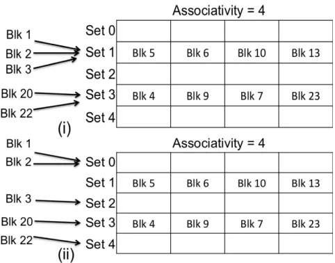
Figure 2.3: (i) Blocks mapped to set whose all lines are already utilized, i.e. conflict misses, (ii) Blocks mapped to unutilized sets, i.e. effect of efficient indexing scheme.
2.2 Conflict Miss Handling
The performance of cache memory can be improved by reducing cache misses. This thesis focuses on increasing the efficiency of the cache by reducing the conflict misses. Conflict misses can be reduced by increasing associativity since there will be more positions available to map a block to a set. However, it will introduce extra hardware logic due to the need to perform more tag comparisons. It will increase the hit time and therefore increase overall access time (see Equation 1.1). Another possible way is to utilize the cache capacity efficiently. The cache accesses are limited to specific sets, and lots of cache area remains unused. This problem can be resolved using a better indexing scheme which helps to scatter the accesses within the cache.
Refer to Figure 2.3 to find that with a conventional indexing scheme the blocks Blk1, Blk2, Blk3 maps to Set1 and Blk20, Blk22 maps to Set3. Both Set1 and Set3 are full which results in conflict misses and the space in Set0, Set2 and Set4 is unutilized. Hence, it reflects that it is better to use the indexing scheme such that the new blocks maps with the sets with unutilized space to
Figure 2.4: Modulus based indexing scheme
reduce conflict misses and therefore to increase system performance.
2.3 Indexing schemes
This section discusses briefly on the conventional modulus based indexing scheme and moti-vation behind this proposed scheme.
2.3.1 Modulus based indexing scheme
The modulus-based indexing scheme is commonly used to index the cache. Figure 2.4 shows how the address is used to index the cache, where B is the block size and S is the number of sets. For example, we have requested an address A, i.e. 0XF0123456 for a two way associative and 8 KB cache (8192 bytes) and each line size is 16 bytes. Since the line size is 16 bytes, then offset will be the last 4 bits of the address, i.e. 0X6. The number of sets is 256. It can be calculated using Equation 2.1.Thus the number of bits required to represent a set is 8, and hence the indexed set is 0X45. The remaining bits indicate the tag, i.e. 0XF0123.
N umber of sets = cachesize /(associativity ∗ blocksize) (2.1)
2.3.2 Matrix based indexing scheme
Qureshi et al [1] proposed a wear leveling scheme to enhance the lifetime of phase-change main memory. Simple schemes like random invertible binary matrix (RIB) and Feistel Network are used to reduce the probability of lines being frequently written spatially. In RIB based scheme, the block address is treated as a binary vector and multiplied by a random invertible binary matrix
to produce a transformed block address, thus allowing a more even distribution of accesses to the memory. Similar behavior was seen in the cache memory.
Most of the cache space is unused [5, 6, 9, 10] since the lines are mapped densely to some sets. Hence, it motivates the application of the idea of RIB matrix in this thesis, and further evaluate whether it helps in spreading the accesses evenly in the cache memory.
3. RELATED WORK
This chapter gives an overview of the various replacement policies, and different indexing schemes for handling conflict misses, some of which are used for the evaluation of proposed in-dexing scheme for set-associative and direct-mapped cache. Table 3.1 shows a list of inin-dexing schemes that are briefly explained in this chapter.
3.1 Re-Reference Interval Prediction
Applications show different access patterns which leads to different cache behavior. Least Recently Used (LRU) policy performs poorly when the working set of the application is more than the cache size (i.e. thrashing patterns) [11]. LRU relates recency with re-reference of the cache block and treats that recently accessed block will have near immediate future. There are applications, which have frequent bursts of non-temporal data (i.e. scan patterns) and also do not perform well with LRU.
Jaleel et al. proposed the Static Re-reference interval prediction (SRRIP) technique which performs well on scan patterns and Dynamic Re-reference interval prediction technique (DRRIP) which performs well on the scan as well as on thresh patterns [11]. Each block in the cache has a Re-reference prediction value (RRPV). When RRPV is 2 bit, then it could have four possible values, i.e. 0 for near immediate re-reference, 1 is near re-reference, 2 is long, and 3 is distant re-reference. The RRPV value is set to 2, 0 and 3 in case of block insertion, hit and miss respec-tively. DRRIP performs set duelling between SRRIP and thrash resistant BRRIP (Bimodal RRIP) technique. BRRIP prevents thrashing by inserting blocks with RRPV value 3 for most of the times and inserts blocks with RRPV value as 2 with less probability.
SRRIP and DRRIP improve performance on an average of 4% and 10% respectively over LRU for single-core configuration. For multi-programmed configuration, SRRIP and DRRIP improve average performance by 7% and 9% over LRU.
3.2 Sampling-Based Dead Block Prediction
A cache bridges the processing speed gap between memory and CPU by keeping frequently accessed blocks. Therefore it is preferred to keep only the valuable blocks in it. However, some blocks are never accessed from the time they enter the cache. These blocks are called as dead blocks and should be evicted soon to utilize the cache space efficiently.
Khan et al. proposed sampling dead block prediction (SDBP), a technique to manage LLC efficiently by predicting the dead blocks and preventing their placement in the cache [12]. The authors have used a sampler that generalizes the entire cache by keeping a few sets, and reducing the overhead of metadata. This policy uses a predictor, which constitutes three tables of 2 bit saturating counter. Each table is indexed in a skewed fashion [10] by using different hashing functions over the instruction program counter(PC), which is accessing memory. During a block placement in the cache, we check the predictor and bypass the cache when it predicts that a block is dead. On hit, the counter values in the tables will be decremented corresponding to the accessed block, and these values will be incremented in case of eviction.
This policy keeps less metadata than other dead block predictors. SDBP outperforms LRU with a geometric mean speedup of 5.9% and 12.5% for single thread and multi-programmed workloads.
3.3 Signature-Based Hit Predictor
Wu et al. proposed a signature-based hit predictor (SHiP) that improves the cache performance by correlating the re-reference behavior of a cache line with a unique signature [13]. This approach is similar to the dead block prediction, SDBP focuses on predicting the dead blocks while SHiP focuses on predicting live blocks. Each cache reference has an outcome bit and a signature. A signature could be an instruction PC, the most significant bits of the data address, or instruction sequence history.
Similar to SDBP, this policy has used a predictor, which is a table of 2 bits saturating counters and indexed by hashed signature. The baseline policy used for cache is RRIP. In case of a hit, the counter values in the predictor table are increased, and the outcome bit associated with the
block is made valid. In case of a miss, if the block is not accessed even once, i.e. its outcome bit is false, then the counter values are decreased corresponding to the signature of an evicted block. The outcome bit is reset when the evicted block is accessed once, and signature value is updated with the value of incoming block signature. During the eviction, the predictor is accessed using incoming block signature, and if the counter value is 0, the block is predicted as a distant re-reference, i.e. RRPV value is 3 else it has an intermediate reference, i.e. RRPV value is 2.
This technique improves the application performance by 10% and 12% over LRU replacement for single thread and multi-programmed workloads respectively.
3.4 Evicted Address Filter
Earlier works on cache memory have addressed the problem of pollution and thrashing sep-arately. Vivek et al. proposed a technique to handle both issues together by keeping track of reusability of accessed cache blocks [14].
A structure called as evicted address filter (EAF) is introduced to keep the addresses of a recently evicted blocks. On a cache miss, when a block is found in EAF, then it will be placed at most recently used position in the cache. When a block is not present in EAF, it means that it has low reuse and thus it will be placed in LRU position. EAF suffers from the problem of significant storage overhead and high associative lookups. Thus authors proposed to implement EAF as Bloom filter. When an address is inserted in bloom filter, then the value at the bit position corresponding to the hash of address value is set to 1. Also, the presence of a block in EAF is checked by taking the hash value of the address and then it is compared to 1. All the addresses from the bloom filter are cleared when all the bits are set to 1.
This technique shows the speedup of 7% over LRU for single-threaded workloads, and the weighted speedup is 15% over LRU and 8% over SHIP for multi-programmed workloads.
3.5 Kill the Program Counter
Prefetching and cache replacement schemes are among the dominant research topics for effi-cient cache management. However, there is limited work done on studying the interaction between
both the schemes [15, 16, 17]. These studies show that prefetching can affect replacement policies positively as well as negatively.
Kim et al. proposed an efficient approach which uses prefetching and a replacement policy together to manage all levels of cache [18]. Traditional prefetching schemes do not use the PC and do not help in learning of PC-based replacement policies. In addition to that, passing the PC to microarchitecture subsystems needs extra logic and wires. Thus, the authors have proposed the replacement policy component called KPC-R and a prefetcher component called KPC-P, which learns from each other. These approaches improve the system performance as well as reduces the hardware overhead by not using the PC.
In KPC-P, a pattern table is used to store the compressed history of L1 misses, and it is indexed using the history to predict the next block. During the initial training phase, the counter values are increased which gives the confidence that prefetchers are useful. After the training phase, prefetchers are used only if the confidence on prediction is high.
The KPC-R replacement policy uses global hysteresis to predict dead blocks by tracking global reuse behavior [18]. The hysteresis value is maintained for cache demands and prefetches. This scheme uses a sampler, which is managed using true LRU. The cache uses SRRIP replacement policy. The value for Demand Global Hysteresis (DGH) or Prefetch Global Hysteresis (PGH) (based on its allocation type) is decremented on a cache hit in one of the sampler sets. The value is incremented on a sampler miss when the victim was never used. When the value for DGH or PGH is saturated, then the accessed blocks are predicted to be dead.
KPC outperforms baseline DA-AMPM+LRU [17], SHIP, PACMan [15], UMO [17] with a ge-ometric speedup of 9.2%, 5%, 5.8%, 8.1% for single core simulations respectively. KPC achieves the weighted speedup of 14.1% over baseline DA-AMPM+LRU and 8.1% over SHIP respectively for multi-programmed configuration.
3.6 Multiperspective Reuse Prediction
Jiménez et al. proposed multiperspective reuse prediction (MRP) [19], which uses a machine learning based perceptron [20] technique to predict the importance of cache blocks. Different
features which track the reuse of memory and program behavior are fed as inputs to the predictor. A genetic algorithm is used for design space exploration to get the best features, so that a better predictor accuracy is yield over the set of input traces. Authors have used features that correlate well with block reuse, i.e. PC, memory address, bias, burst, insert, last miss and offset. The predictor is a set of tables, one per feature and its index is obtained using feature value exored with PC. Each table works as a perceptron predictor. The authors have also used a sampler that is used to train the predictor on every access. On sampler access, when a block gets demoted beyond the recency position for a feature, then the predictor table for that feature is trained that the block is dead. The predictor table for a feature is not trained that the access is reuse when the block is accessed beyond the recency position. On each cache access, the predictor is accessed to decide if the block should be bypassed, placed or promoted in the cache.
This technique yields a geometric mean speedup of 9.0%, 5.1%, 6.3% over LRU, Hawk-eye [21], and Perceptron [22] respectively for single-thread benchmarks. It yields a weighted speedup of 8.3%, 5.2%, 5.8% over LRU, Hawkeye, and Perceptron respectively for multipro-grammed configuration.
3.7 Indexing schemes
Randomizing the mapping of references in memory modules is one of the prominent areas of research in microarchitecture. The objective of randomization is to reduce the conflict misses and allow uniform distribution of accesses with an efficient utilization of the available space. These randomizing schemes also help in eliminating the interleaving bottleneck for an efficient banking scheme.
Some of the earliest works was to use a victim buffer [23], virtual victim cache [24] that gave an illusion of more associativity and helped in reducing the conflict misses in direct mapped cache at the expense of extra hit latency. After that, researchers proposed various mathematics based schemes such as use of Prime modulus functions [7, 25, 26], XOR-based hashing [27, 28], Skewing [10, 29, 30] and Pseudo-random functions [31, 32, 33].
interleaving scheme to get high bandwidth [32]. In this scheme, the randomization is achieved by XORing the physical address with a bit pattern that changes using polynomial arithmetic.
González et al. analyzed the XOR-based hashing function and have shown that it elimi-nates the conflict misses for different cache organizations [6], similar to direct-mapped [34], set-associative [34], column-set-associative [35], and hash-rehash cache [9]. Authors also proposed a bitwise XOR mapping scheme that forms the index by taking XOR of some bits from the tag and set index.
Seznec used the XOR-based hash function followed by circular shift and proposed an idea of Skewed Associative cache [10]. A line maps to the same set in all banks in an X way set associative cache using conventional modulus based indexing scheme, where each way works like a bank. However, in this organization, the mapping of a line is different for different banks. Different hash functions are used to generate the different index values, and this ensures the scattering of data in the cache. An X way cache with skewed mapping results in performance equivalent to 2X way cache and with same hardware overhead as X way cache. However, this scheme leads to pathological behavior because XOR-ing with different values for each set access affects the locality.
Kharbutli et al. proposed two new prime number based hashing functions [7], i.e. prime mod-ulo and prime displacement, which outperforms the widely used XOR based hashing functions. These new schemes spread the cache accesses in a better way by keeping the locality. The prime modulo scheme generates cache index by performing address modulo number of sets. However, the number of sets is not a power of two, and it is a prime number. The prime displacement scheme generates the index by adding an extra term to address modulo number of sets. Here, the number of sets is a power of two, and the additional term is a prime number multiplied by tag bits.
Balanced cache is another technique to reduce the miss rate of direct-mapped cache by in-creasing the decoder length [5]. The two most significant set index bits are used as an input to programmable decoders, and the least two significant bits are used as input to non-programmable decoders. Previously proposed schemes restrict the modulus to either power of 2 or a prime
num-Prime number based [7, 10, 25, 26] Xor based hashing [6, 10, 26, 32, 37] Polynomial based scheme [31, 32, 33, 36]
Programmable decoders [5]
Table 3.1: Indexing schemes
ber.
Jeffery et al. proposed Arbitrary modulus indexing (AMI) scheme which gives the flexibility to use any number for modulus operation [8]. It provides the division and modulus result simulta-neously and makes the scheme efficient. These indexing schemes are also used by researchers to eliminate the intra-warp conflicts in GPU.
Khairy et al. have proposed a pseudo-random interleaved scheme which is based on polynomial based modulus mapping [36]. In this scheme, a memory location is expressed as a polynomial with random coefficients.
Wang et al. proposed a full permutation (FUP) cache indexing scheme to minimize warp conflicts by using a combination of prime modulo and XOR-based hashing scheme [37].
4. APPROACH
Cache memory speeds up the working mechanism of CPU by storing the frequently accessed data and reducing the performance gap between CPU and main memory. Conflict misses are one of the significant problems that hamper the cache performance and impact system performance. Conflict misses occur due to the mapping of blocks to the same position in the cache and thereby evicting the useful information. These collisions can be prevented by modifying the indexing scheme, such that the address used for indexing could be more random. This chapter discusses the idea of the matrix-based indexing scheme and its algorithm.
4.1 Matrix based Indexing scheme
In conventional modulus-based indexing scheme, first, the requested address by CPU is split into three parts, i.e. tag, set and offset as seen in Section 2.3.1. The set index bits are used to find the mapping position in the cache, where the requested tag is matched with the tag values present in the indexed set. The offset indicates the requested byte or word. However, it leads to conflict misses.
This thesis proposes a matrix-based indexing scheme and evaluates if it is useful in reducing the conflict misses. This scheme uses an invertible binary matrix for the computation of the new randomized address as seen in Figure 4.3.
4.1.1 Invertible Matrices
This technique uses an invertible binary matrix to spread cache accesses. This scheme must map each physical address to exactly one randomized new address to ensure correctness. Thus, the matrices used must be invertible [38].
A matrix is invertible if and only if it holds the following conditions: 1. It should be a square matrix.
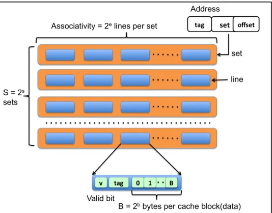
Figure 4.1: reprinted from: Binary arithmetic in Matrix based indexing scheme [1]
A RIB constitutes 0 and 1. It has the same size as the block address, i.e. equal to the total sum of the number of bits in the tag and set. Out of the generated matrices, ten different invertible matrices for our experiments were randomly picked (see Appendix A).
4.1.2 Algorithm
Algorithm 1 shows the primary steps taken in this scheme. Line 4 shows that the matrix-based indexing scheme is only applied for LLC and conventional indexing scheme is used in other cache levels. The RIB matA is read from a text file and used as an input in function apply_matrix to gen-erate a new randomized address, as seen in Algorithm 2, line 1. The matB and matC are temporary matrices used to perform binary arithmetic as shown in Figure 4.1. This new randomized address is further used to index the cache memory, instead of an actual physical address, also shown in Fig-ure 4.3. Each bit in the new address is obtained by multiplying one row of the RIB matrix with the physical address. The multiplication and addition are the AND and XOR operations respectively, as shown in Figure 4.1 and Figure 4.2.
For instance, the requested cache address is 0xabcde for a four-way set associative cache with a 16-bytes block size. The offset part is 0xe, and the block address is 0xabcd (see Section 2.3.1 for the calculations). The address is a physical address since this scheme is either applied to LLC or
Figure 4.2: New Randomized address after Binary arithmetic
both second level cache and LLC. To get a new randomized block address, we will perform binary arithmetic of the physical address with RIB matrix as shown in Figure 4.1 and Figure 4.2. For example, the first bit of new address 0XABCD is obtained using Equation 4.1. The new set index is computed from the new address, and the old tag value is stored at the cache line.
A= (a and0 )xor(b and1 )xor(c and1 )xor(d and1 ) (4.1)
The storage and latency overhead for this algorithm is miniscule for RIB matrix N x N, where N is taken as 32 for matrix based indexing scheme. The storage used isN2 bits and the latency is the delay oflog2(N) logic gates [1].
Algorithm 1Matrix based indexing scheme: set calculation. 1: matA[size][size]←read from file
2: functionGET_SET(address) 3: set←0
4: ifcache_type==LLCthen
5: new_address←apply_matrix(matA,address) 6: set← new_address &(2numset−1)
7: else
8: set← address &(2numset−1)
returnset
Algorithm 2Matrix based indexing scheme: calculation of the new randomized address. 1: functionAPPLY_MATRIX(mat[size][size],address)
2: matB[size][1]←initialized to 0 3: matC[size][1]←initialized to 0 4: new_address←0
5: fori= 0to sizedo
6: matB[i][0]←address &2i
7: mult((matA,matB,matC)
8: fori= 0to sizedo
9: ifmatC[i][0]then
10: new_address← new_address |2i
returnnew_address
11: functionMULT(matA[size][size],matB[size][1],matC[size][1]) 12: fori= 0to sizedo
13: temp_var←0
14: forj= 0to sizedo
15: temp_var← temp_var xor(matA[i][j] &matB[j][0]) 16: matC[i][0]←temp_var
5. METHODOLOGY
This chapter discusses the methodology used to evaluate the proposed indexing technique. It also discusses the simulator, its configuration detail and performance metrics used for the results evaluation.
5.1 Host machine
This section discusses the experimental setup used for evaluating the new indexing technique. The Private cluster of Texas Architecture and Compiler Optimizations research group (TACO) is used for the experiments. The cluster has many different machines with Intel, AMD and ARM ma-chines with different amounts of DRAM. Terra supercomputer, part of the Texas A&M University supercomputing facilities is used for the multi-programmed configurations. This supercomputer uses Slurm as a workload manager [39].
5.2 Benchmarks
The experiments for single and multicore configurations are performed using single threaded applications. 27 SPEC CPU2006 [40] applications as listed in Table 5.1, 20 SPEC CPU2017 [41] applications as listed in Table 5.2, 3 CloudSuite [42] and 1 machine learning application [43] as listed in Table 5.3 are used.
The traces for SPEC CPU2006 and SPEC CPU2017 were collected with SimPoint [44, 45]. The CloudSuite and ml_pack traces were collected after fast-forwarding at least 30 billion in-structions. The execution of traces constitutes 2 phases: warm-up and timing phase. During the warm-up phase, the state of microarchitecture subsystems will get initialized, and after that, the point timing simulation starts. For single core simulations, 200 million and 1 billion instructions are used for warm-up and timing simulation phase respectively.
For multicore simulations, the warm-up phase is 200 million instructions, and the timing sim-ulation phase is 1 billion instructions, such that each trace runs until all the traces have finished at least one billion instructions. The experiments used four cores, i.e. a mix used for multicore
con-astar libquantum bwaves bzip2 cactusADM calculix
gamess milc gobmk
mcf omnetpp h264ref
gcc soplex hmmer
GemsFDTD sphinx3 namd
gromacs wrf perlbench
lbm xalancbmk povray
leslie3d zeusmp sjeng
Table 5.1: SPEC CPU2006 benchmarks.
perlbench_s gcc_s bwaves_s mcf_s cactuBSSN_s lbm_s omnetpp_s wrf_s xalancbmk_s x264_s cam4_s pop2_s deepsjeng_s imagick_s leela_s nab_s exchange2_s fotonik3d_s rom_s xz_s
Table 5.2: SPEC CPU2017 benchmarks.
data_caching graph_analytics
sat_solver mlpack_cf
Mix 1 mlpack_cf mlpack_cf mlpack_cf mlpack_cf Mix 2 graph_analytics sat_solver data_caching graph_analytics Mix 3 graph_analytics sat_solver data_caching sat_solver Mix 4 graph_analytics sat_solver data_caching data_caching
Table 5.4: Multiprogrammed CloudSuite and machine learning mixes for simulating 4 cores.
Mix 1 astar leslie3d soplex zeusmp
Mix 2 mcf milc omnetpp h264ref
Mix 3 astar cactusADM leslie3d zeusmp
Mix 4 cactusADM gromacs sphinx3 mcf
Mix 5 cactusADM gromacs lbm milc
Mix 6 cactusADM GemsFDTD lbm leslie3d
Mix 7 gromacs libquantum mcf sphinx3
Mix 8 astar bzip2 sphinx3 gamess
Mix 9 bzip2 omnetpp calculix sjeng
Mix 10 wrf perlbench sphinx3 xalancbmk
Table 5.5: Multiprogrammed SPEC CPU2006 mixes for simulating 4 cores.
figuration has four traces such that each trace runs on a core. The experiment also used 20 mixes from SPEC CPU2017, 10 mixes from SPEC CPU 2006 and 3 mixes from CloudSuite and 1 mix for machine learning application for multicore simulations. The mixes are generated randomly and are listed in Table 5.6, 5.5, and 5.4.
5.3 Simulator
The extended version of ChampSim simulator [46], used in the 2nd data prefetching cham-pionship and also in the 2nd cache replacement chamcham-pionship is used for the experiments. It is used for modeling different cache configurations and for studying the impact of the proposed in-dexing scheme on system performance. We have used Cacti [47] to compute the hit latency for set-associative cache and direct-mapped LLC (see Section 5.4).The simulator configuration is de-scribed in Table 5.7. The baseline consists of a three-level non-inclusive cache hierarchy, where all three levels have traditional modulus-based indexing scheme. The KPC-P prefetcher is enabled
Mix1 bwaves_s lbm_s xalancbmk_s exchange2_s
Mix2 nab_s cactuBSSN_s omnetpp_s lbm_s
Mix3 deepsjeng_s omnetpp_s lbm_s bwaves_s
Mix4 fotonik3d_s omnetpp_s xz_s exchange2_s
Mix5 fotonik3d_s pop2_s omnetpp_s x264_s
Mix6 lbm_s leela_s fotonik3d_s pop2_s
Mix7 omnetpp_s roms_s lbm_s roms_s
Mix8 xalancbmk_s l perlbench_s roms_s exchange2_s
Mix9 roms_s nab_s xalancbmk_s roms_s
Mix10 roms_s x264_s xalancbmk_s wrf_s
Mix11 lbm_s bwaves_s fotonik3d_s nab_s
Mix12 xalancbmk_s leela_s lbm_s cactuBSSN_s
Mix13 omnetpp_s lbm_s omnetpp_s bwaves_s
Mix14 xalancbmk_s lbm_s xalancbmk_s cactuBSSN_s
Mix15 x264_s lbm_s lbm_s omnetpp_s Mix16 roms_s mcf_s x264_s mcf_s Mix17 mcf_s xalancbmk_s mcf_s lbm_s Mix18 mcf_s mcf_s cactuBSSN_s lbm_s Mix19 xz_s roms_s mcf_s mcf_s Mix20 lbm_s mcf_s omnetpp_s mcf_s
Table 5.6: Multiprogrammed SPEC CPU2017 mixes for simulating 4 cores.
only for the second level of Cache.
Parameter Configuration
L1 I-Cache 32KB, 64B blocks, 8-way, (private) 8 MSHRs, 1 cycle latency,
64 read/write/prefetch queue size L1 D-Cache 32KB, 64B blocks, 8-way,
(private) 8 MSHRs, 4 cycles latency, 64 read/write/prefetch queue size L2 unified Cache 256KB, 64B blocks, 8-way
Parameter Configuration
(private) 16 MSHRs, 8 cycles latency, 32 read/write/prefetch queue size
non-inclusive
L3 unified Cache 2MB per core, 64B blocks, 1/16-way (shared) 32 MSHRs, 12/20 cycles latency
(Direct Mapped/Set Associative configuration),
16 per core read/write/prefetch queue size non-inclusive
Frequency 4GHz
Page size 4KB
Fetch, decode and retire 4 wide
Execution 6 wide
Load Queue 2 wide
Store Queue 1 wide
DRAM row precharge latency 11 cycles
DRAM row address to column
address latency 11 cycles
DRAM column address
strobe latency 11 cycles
DRAM 2 channels (1 DIMM per channel), 8 banks (64MB per bank), 8 ranks (512MB per rank),
4GB per DIMM Table 5.7: Simulator configuration
Parameter Configuration
DRAM channel width 8
DRAM I/O frequency 800MHz
Branch Predictor Perceptron
Reorder Buffer size 256
Pipeline depth 5
Table 5.7: Continued.
5.4 Experimental Configuration
This section describes the cache configurations simulated for evaluating the proposed scheme. The parameters that are changed: replacement policy, indexing scheme, cache associativity, the number of cores, and RIB matrices. The conventional indexing scheme (as seen in Section 2.3.1) is used for all cache levels in baseline experiments. KPC-P prefetching scheme is enabled for the second level of cache for all the configurations.
We performed four experiments to evaluate the new scheme for single-threaded and multi-programmed workloads. The experiments performed are:
1. Evaluation and comparison of the traditional and new scheme for direct mapped LLC. Other levels of cache are set associative.
2. Evaluation of the new indexing scheme for direct mapped LLC with baseline as traditional indexing scheme applied for set associative LLC. Other levels of cache are set associative. 3. Evaluation of the traditional and proposed indexing scheme for six replacement policies (as
seen in Section 3) in LLC: LRU, DRRIP, EAF, MRP, SHIP, KPC-R. Other levels of cache have used LRU, and the matrix based indexing scheme is enabled only in LLC.
4. The results are compared when the new indexing scheme is enabled only for LLC, and when it is allowed for both second level cache and LLC. LRU is used as a replacement policy for all cache levels.
The motivation behind the direct mapped LLC related experiments is to explore the possibility of using LLC as direct mapped cache and thus taking advantage of hit latency. For single core simulations, the second experiment is performed for RIB matrix 3 and 4 (see Appendix A) and another set of experiments are performed for ten RIB matrices. All the simulations for multicore configurations are performed for RIB matrix 3 and 4. In the first experiment, the LLC is a direct mapped cache. In the last two set of experiments, all cache levels are set-associative.
5.5 Performance Evaluation
Geometric mean speedup [4] is used as the performance metric. For the single core configu-ration, the speedup for an application is computed by extracting the instructions per cycle (IPC) from the results, and dividing IPC of configuration i with IPC of baseline, as seen in Equation 5.1.
Speedupi =IP Ci/IP Cbaseline (5.1)
For the multi-core simulations, the computation of speedup for a configuration i over the base-line running a particular mix is obtained by computing the average IPC across all threads, and dividing it by the average IPC across all thread in the baseline, as seen in Equation 5.2.
Speedupi =AverageIP Ci/AverageIP Cbaseline (5.2)
Here the reported speedup for an application is the average speedup (obtained using tion 5.1 or Equation 5.2) across all the N RIB matrices used for an experiment as shown in Equa-tion 5.3.
Speedupapplication = N
X
n=1
(Speedupapplicationf or RIBn)
Then the geometric mean speedup is computed over speedup of all the K applications in the trace suite as shown in Equation 5.4.
Geomeanspeedup= K v u u t K Y i=1 (Speedupapplication_i) (5.4)
6. RESULTS
This chapter discusses the results obtained during the course of this work. We ran four ex-periments for single-threaded and multi-programmed workloads: LLC as direct mapped cache, interaction of indexing scheme applied to set associative and direct mapped LLC cache, and in-teraction of indexing scheme with different replacement policies (see Section 5.4). We ran these experiments for multiple sets of RIB matrices (see Appendix A). For each experiment, we used two sets of benchmarks. The first set contains the SPEC CPU2006, CloudSuite and machine learning benchmarks. The second set contains the SPEC CPU2017 benchmarks. We used the geometric mean speedup as the performance metric as described in Section 5.5.
6.1 Single-Core Results
This section describes the results of the single-core simulations. Appendix B contains the results for each RIB matrix used for the three experiments. The following subsections analyze the impact of using the proposed indexing scheme with direct-mapped cache organization, different replacement policies and when it is applied to different levels of cache.
6.1.1 Direct mapped cache
This study compared the conventional scheme with matrix-based indexing for direct-mapped LLC (see Experiment 1 in Section 5.4). The other cache levels are set associative. The replacement policy is LRU for all cache levels. The results are reported as the geometric mean speedup of the benchmarks over the average of ten sets of RIB matrices (see Appendix A), as discussed in Section 5.5.
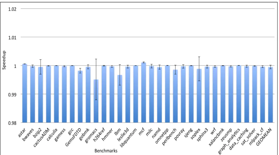
Figure 6.1 shows the geometric mean speedup across SPEC CPU2006, CloudSuite and ma-chine learning benchmarks and confidence intervals showing standard deviation above and below the mean. The matrix-based indexing scheme yields an improvement of nearly 0.8% which reflects that, it has a little impact on the performance. However, the new scheme does not significantly slow down any benchmarks except bzip2. The performance significantly improves nearly 9% for
com-putation intensive lbm and libquantum traces. Also, it improves performance by at least 2%, 4% for sixteen and eight of SPEC CPU2006 benchmarks respectively. We can see a considerable variation in speedup values from mat1 to mat10 for bzip2 and mlpack_cf.
Figure 6.2 shows the geometric mean speedup the across SPEC CPU2017 benchmarks and confidence intervals over the mean. The matrix-based scheme performs better for SPEC CPU2017 than SPEC CPU2006 benchmarks, it yields a geometric mean speedup of 1.2%. This scheme improves performance by 1.5% and 4% for at least eighteen and seven of SPEC CPU2017 appli-cations respectively. A significant improvement of 7% is observed for lbm and cactuBSSN traces, widely used for physics-based computations. There is a degradation of 2% in average performance for mcf_s. However there is negligible degradation for some matrices, which can be seen by the positive error bar over the mean value. Also, there is significant variation in speedup values over ten RIB matrices for cactuBSSN_s, lbm_s, and xalancbmk_s.
In another study, we have compared the new indexing scheme applied to direct-mapped LLC with conventional indexing scheme applied to set associative LLC (see Experiment 2 in Sec-tion 5.4). Figure 6.3 shows the geometric mean speedup across SPEC CPU2006, CloudSuite and machine learning benchmarks. The overall performance of direct-mapped LLC with matrix-based indexing scheme is degraded by 1% over the set associative cache. The matrix-based indexing scheme shows a significant improvement for these traces: bzip2 by 7%; perlbench by 2%; and data_caching by 2%. There is a big variation in speedup values over mean for bzip2, mlpack_cf, hmmer and soplex benchmarks. Figure 6.4 shows the geometric mean speedup the across SPEC CPU2017 benchmarks. The new indexing scheme with direct mapped LLC shows same overall performance as set associative cache. The new scheme shows significant improvement for these traces: mcf_s by 10%; xalancbmk_s by 3.9%; pop2_s by 2%. Also, we can see a notable difference in the values of ten RIB matrices for mcf_s, cactuBSSN_s, lbm_s and xalancbmk_s.
6.1.2 Replacement Policy Impact
This study compares the conventional scheme with matrix-based indexing for LLC with differ-ent replacemdiffer-ent policies (see Experimdiffer-ent 3 in Section 5.4). LRU is used as a replacemdiffer-ent policy for
the other cache levels. The results are reported as the geometric mean speedup of the benchmarks over an average of the RIB matrices 3 and 4 (refer Appendix A), as discussed in Section 5.5.
Figure 6.5 shows the geometric mean speedup across SPEC CPU2006, CloudSuite and ma-chine learning benchmarks for different replacement policies. The geometric mean speedup results over all the traces are 0.3% which shows that the matrix-based scheme does not correlate well with different replacement policies and has a negligible impact on the cache performance. However, LRU with the proposed indexing scheme shows a huge benefit of 5.2% for the machine learning benchmark. Also, all the replacement policies except MRP improve performance by at least 2% and 3.4% for lbm and libquantum. MRP policy is the most accurate dead block predictor in lit-erature. It predicts dead blocks efficiently and create more space in cache. The MRP policy with the matrix-based indexing scheme shows a significant deviation in speedup values from mean for GemsFDTD, zeusmp, leslie3d, and wrf. Also, it shows a remarkable performance improvement for memory intensive traces: GemsFDTD by 36%; zeusmp by 5.3%; leslie3d by 6.1% and wrf by 3.8%.
Figure 6.6 shows that the geometric mean speedup and confidence intervals over mean value. The performance improvement for all the replacement policies (except MRP) is nearly 0.2%, which shows that the new indexing scheme does not benefit SPEC CPU2017 applications. However, the new scheme does not cause significant slowdown either. The matrix-based indexing scheme with the MRP replacement policy improves the performance by 1.2%. All the replacement policies except KPC-R benefit for lbm, fotonik and cam4 trace by an improvement of nearly 2%. The combination of MRP and new indexing scheme shows significant variation in speedup values for RIB matrices and performance improvement: cactuBSSN by 5.6%; lbm by 3.2%; wrf by 3.6%; pop2 by 2.5%; roms by 13%.
6.1.3 Impact of indexing on different cache levels
This section discusses the results obtained when the matrix-based indexing is enabled for both the second and the last cache levels compared to when it is enabled only in the LLC (see Experi-ment 4 in Section 5.4). The replaceExperi-ment policy for all cache levels is LRU. The results are reported
![Figure 4.1: reprinted from: Binary arithmetic in Matrix based indexing scheme [1]](https://thumb-us.123doks.com/thumbv2/123dok_us/10174156.2919711/40.918.189.729.106.376/figure-reprinted-binary-arithmetic-matrix-based-indexing-scheme.webp)