Hardware Installation
2015-04-28 17:41:17 UTC
Contents
Hardware Installation ... 4
Hardware Installation ... 5
Introduction to the Hardware Platforms ... 6
Common Hardware Components ... 7
LCD Display ... 8
Ports ... 13
Field Replaceable Units... 21
Power Supply... 22
CompactFlash Card... 26
Solid-State Drive... 29
Hard Disk Drive ... 32
Direct Attach Cable ... 34
Hardware Platforms... 36
Citrix NetScaler 9010 FIPS ... 37
Citrix NetScaler 12000-10G... 39
Citrix NetScaler MPX 5500 ... 41
Citrix NetScaler MPX 5550 and MPX 5650 ... 43
Citrix NetScaler MPX 7500 and MPX 9500 ... 45
Citrix NetScaler MPX 8200, MPX 8400, MPX 8600, and MPX 8800 48 Citrix NetScaler MPX 9700, MPX 10500, MPX 12500, and MPX 15500 51 Citrix NetScaler MPX 11500,MPX 13500,MPX 14500,MPX 16500,MPX 18500, andMPX 20500 ... 54
Citrix NetScaler MPX 11515, MPX 11520, MPX 11530, MPX 11540, and MPX 11542... 56
Citrix NetScaler MPX 15000 ... 58
Citrix NetScaler MPX 17000 ... 60
Citrix NetScaler MPX 17500, MPX 19500, and MPX 21500... 62
Citrix NetScaler MPX 17550, MPX 19550, MPX 20550, and MPX 21550 64 Citrix NetScaler MPX 22040, MPX 22060, MPX 22080, MPX 22100, and MPX 22120... 66
Preparing for Installation ... 75
Unpacking the Appliance... 76
Preparing the Site and Rack ... 77
Cautions and Warnings ... 79
Installing the Hardware ... 82
Rack Mounting the Appliance... 83
Installing and Removing 1G SFP Transceivers... 88
Installing and Removing XFP and 10G SFP+ Transceivers ... 91
Connecting the Cables... 95
Switching on the Appliance ... 98
Initial Configuration ... 99
Using the LCD Keypad ... 100
Using the NetScaler Serial Console ... 102
Using the Setup Wizard... 105
Using DHCP for Initial Access ... 107
Accessing a NetScaler by Using SSH Keys and No Password... 112
Changing the Administrative Password ... 115
Lights Out Management Port of the NetScaler Appliance ... 116
Migrating the Configuration of an Existing NetScaler Appliance to Another NetScaler Appliance ... 121
Troubleshooting... 123
Hardware Installation
The following sections describe the hardware installation and initial configuration for all NetScaler hardware platforms.
Introduction to the Hardware Platforms Describes the NetScaler hardware platforms and provides detailed
information about each platform and its components.
Preparing for Installation Describes how to unpack the NetScaler appliance and prepare the site and rack for installing the appliance. Lists the cautions and warnings that you should review before you install the appliance. Installing the Hardware Describes the steps to install the rails,
mount the hardware, connect the cables, and turn on the appliance.
Initial Configuration Describes how to perform initial
configuration of your NetScaler appliance and assign management and network IP addresses.
Lights Out Management Port of the NetScaler Appliance
Describes the different operations you can perform on your NetScaler appliance by using the Lights Out Management Port. For information about NetScaler hardware and software compatibility and the supported upgrade and downgrade paths, see http://support.citrix.com/article/CTX113357.
5
Introduction to the Hardware Platforms
The NetScaler hardware platforms range from the single processor MPX 5500 platform to the high-capacity, MPX 22040/22060/22080/22100/22120 hardware platform. The various NetScaler hardware platforms are similar in that they use the same types of components, but different models provide different hardware capabilities. All NetScaler hardware platforms support the NetScaler software.
Some of the hardware platforms are available as dedicated application firewall appliances or secure application access appliances.
7
Common Hardware Components
Each platform has front panel and back panel hardware components. The front panel has an LCD display and an RS232 serial console port. The number, type, and location of
ports—copper Ethernet, copper and fiber 1G SFP, 10G SFP+, and XFP—vary by hardware platform. The back panel provides access to the fan and the field replaceable units (power supplies, CompactFlash card, and solid-state and hard-disk drives).
LCD Display
The LCD display on the front of every appliance displays messages about the current operating status of the appliance. These messages communicate whether your appliance has started properly and is operating normally. If the appliance is not operating normally, the LCD displays troubleshooting messages.
The LCD displays real-time statistics, diagnostic information, and active alerts. The dimensions of the LCD limit the display to two lines of 16 characters each, causing the displayed information to flow through a sequence of screens. Each screen shows information about a specific function.
The LCD has a neon backlight. Normally, the backlight glows steadily. When there is an active alert, it blinks rapidly. If the alert information exceeds the LCD screen size, the backlight blinks at the beginning of each display screen. When the appliance shuts down, the backlight remains on for one minute and then automatically turns off.
There are nine types of display screens on the LCD display. The first two screens in the following list, the booting screen and the startup screen, appear when your appliance is starting up. The other screens, except the out-of-service screen, can appear while the appliance is operating. They show configuration information, alerts, HTTP information, network traffic information, CPU load information, and port information for your appliance. Booting Screen.
The booting screen is displayed immediately after the appliance is turned on. The first line displays the hardware platform, as shown in the following figure.
Figure 1. LCD Booting Screen
The newer MPX appliances display NSMPX followed by the platform number in the first line. For example, the MPX 7500/9500 appliances display NSMPX-7500. To view the model number, at the NetScaler command line, type show license. Scroll to the end of the command output to view the model number.
Startup Screen.
The startup screen is displayed for a few seconds after the appliance successfully begins operation. The first line displays the hardware platform, and the second line displays the software version and build number, as shown in the following figure.
Figure 2. LCD Startup Screen
The out-of-service screen is displayed when the appliance has undergone a controlled shutdown, as shown in the following figure.
Figure 3. LCD Out-of-service Screen
Configuration Screen.
The first line displays the appliance status (STA, PRI, or SEC) and uptime. STA indicates that the appliance is in standalone mode, PRI indicates that the appliance is a primary node in a high availability (HA) pair, and SEC indicates that the appliance is a secondary node in an HA pair. Appliance uptime is displayed in HH:MM format. The second line displays the IP address of the appliance, as shown in the following figure.
Figure 4. LCD Configuration Screen
Alert Screen.
The first line displays the appliance status (STA, PRI, or SEC). STA indicates that the appliance is in standalone mode, PRI indicates that the appliance is a primary node in a high availability (HA) pair, and SEC indicates that the appliance is a secondary node in an HA pair. The second line displays the IP address of the appliance.
Figure 5. LCD Known Alert Screen
HTTP Statistics Screen.
The first line displays the rate of HTTP GETS per second. The second line displays the rate of HTTP POSTS per second, as shown in the following figure.
Figure 6. LCD HTTP Statistics Screen
Network Traffic Statistics Screen.
The first line displays the rate at which data is received, in megabits per second. The second line displays the rate of data transmission, in megabits per second, as shown in the following figure.
Figure 7. LCD Network Traffic Statistics Screen
LCD Display
CPU Load, Memory, and Connections Screen.
The first line displays CPU utilization and memory utilization as percentages. The second line displays the ratio of the number of server connections to the number of client connections.
Note: If the number of server or client connections exceeds 99,999, the number is displayed in thousands, indicated by the letter K.
Figure 8. LCD CPU Load, Memory, and Connections Screen
Port Information Screen.
The S row displays port speed, flow control, and duplex information. The R row displays megabits received per second on the interface. The first port in each row is the
management port.
Figure 9. Port Information for an 8-port Appliance
Figure 10. Port Information for a 10-port Appliance
The following table defines the various abbreviations and symbols that appear in the S row of the port information screen.
Table 1. Port Abbreviations and Symbols for S Row
S row abbreviation/symbol Indicates
A rate of 10 megabits per second, full duplex mode, and flow control OFF. LCD Display
A rate of 100 megabits per second, full duplex mode, and flow control OFF. A rate of 1 gigabit per second, full duplex mode, and flow control OFF. A rate of 10 gigabits per second, full duplex mode, and flow control OFF. A disconnected port. Note: The R row does not display an abbreviation or symbol for a disconnected port. Receive flow control regardless of speed or duplex mode. Transmit flow control regardless of speed or duplex mode. Receive and transmit flow control regardless of speed or duplex mode. A rate of 10 megabits per second, half duplex mode, and flow control OFF. LCD Display 11
A rate of 100 megabits per second, half duplex mode, and flow control OFF. A rate of 1 gigabit per second, half duplex mode, and flow control OFF. The following table defines the various abbreviations and symbols that appear in the R row of the port information screen.
Table 2. Port Abbreviations and Symbols for R Row
R row abbreviation/symbol Indicates
The port is disabled. Receive speed is about 10% of line speed. Receive speed is about 50% of line speed. Receive speed is about 75% of line speed. Receive speed is about 100% of line speed. LCD Display
13
Ports
Ports are used to connect the appliance to external devices. NetScaler appliances support RS232 serial ports, 10/100/1000Base-T copper Ethernet ports, 1-gigabit copper and fiber 1G SFP ports, and 10-gigabit fiber SFP+ and XFP ports. All NetScaler appliances have a
combination of some or all of these ports. For details on the type and number of ports available on your appliance, see the section describing that platform.
RS232 Serial Port
The RS232 serial console port provides a connection between the appliance and a computer, allowing direct access to the appliance for initial configuration or troubleshooting.
All hardware platforms ship with an appropriate serial cable used to connect your computer to the appliance. For instructions on connecting your computer to the appliance, see "Installing the Hardware."
Copper Ethernet Ports
The copper Ethernet ports installed on many models of the appliance are standard RJ45 ports.
There are two types of copper Ethernet ports that may be installed on your appliance: 10/100BASE-T port
The 10/100BASE-T port has a maximum transmission speed of 100 megabits per second (Mbps). Most platforms have at least one 10/100BASE-T port.
10/100/1000BASE-T port
The 10/100/1000BASE-T port has a maximum transmission speed of 1 gigabit per second, ten times faster than the other type of copper Ethernet port. Most platforms have at least one 10/100/1000Base-T port.
To connect any of these ports to your network, you plug one end of a standard Ethernet cable into the port and plug the other end into the appropriate network connector.
Management Ports
Management ports are standard copper Ethernet ports (RJ45), which are used for direct access to the appliance for system administration functions.
1G SFP, 10G SFP+, and XFP Ports
A 1G SFP port can operate at a speed of 1 Gbps. It accepts either a copper 1G SFP transceiver, for operation as a copper Ethernet port, or a fiber 1G SFP transceiver for operation as a fiber optic port.
The 10G SFP+ and XFP ports are high-speed ports that can operate at speeds of up to 10 Gbps. You need a fiber optic cable to connect to a 10G SFP+ or XFP port. If the other end of the fiber optic cable is attached to a 1G SFP port, the 10G SFP+ port automatically
negotiates to match the speed of the 1G SFP port.
The following tables list the maximum distance specifications for NetScaler pluggable media (1G SFP, 10G SFP+, and XFP transceivers).
Note: The tables are categorized by 1G pluggable media and 10G pluggable media. The 10G SFP+ modules are dual-speed capable and support both 1G and 10G, depending on the peer switch that the model connects to. These are listed in both tables.
Both tables have the following columns:
• SKU: Citrix maintains multiple SKUs for the same part. • Description: The price list description of the part. • Transmit Wavelength: The nominal transmit wavelength.
• Cable/Fiber Type: Fiber characteristics affect the maximum transmit distance
achievable. This is especially true with 10G on multi-mode fiber (MMF), where various dispersion components become dominant. For more information, see
http://www.thefoa.org/tech/ref/basic/fiber.html.
• Typical Reach: Maximum transmit distance.
• Products: Some chassis are available with different media options. Use the appropriate
data sheet to confirm that your particular chassis type supports the media.
1G Pluggable Media
The following table lists the maximum distance specifications for 1G transceivers. Table 1. Copper 1G SFP Distance Specifications
SKU Description Transmitter
Wavelength (nm) Cable Type Typical Reach (m) Products Ports
EW3A0000235, EW3B0000235, EW3C0000235, EW3D0000235, EW3E0000235, EW3F0000235, EW3P0000143, EW3X0000235, EW3Z0000087 Citrix NetScaler 1G SFP Ethernet Copper (100m) - 4 Pack n/a Category 5 (Cat-5) Copper Cable 100 m MPX 7500/9500, MPX 8200/8400/8600/8800, MPX 9700/10500/12500/15500, 12000-10G, 9010 FIPS, MPX 22040/22060/22080/22100/22120
Table 2. Short Reach Fiber 1G SFP Distance Specifications
SKU Description Transmitter
Wavelength (nm)
Fiber Type Typical Reach (m) Products EW3A0000234, EW3B0000234, EW3C0000234, EW3D0000234, EW3E0000234, EW3F0000234, EW3P0000142, EW3X0000234, EW3Z0000086 Citrix NetScaler 1G SFP Ethernet SX (300m) - 4 Pack 850nm (nominal) 50/125um MMF, 2000MHz-km (OM3) 550 m MPX 7500/9500, MPX 8200/8400/8600/8800, MPX 9700/10500/12500/15500, 12000-10G, 9010 FIPS, MPX 22040/22060/22080/22100/22120 50/125um MMF, 500MHz-km (OM2) 550 m 50/125um MMF, 400MHz-km 550 m 62.5/125um MMF, 200MHz-km (OM1) 300 m 62.5/125um MMF, 160MHz-km 300 m
Table 3. Short Reach Fiber 1G SFP Distance Specifications
SKU Description Transmitter
Wavelength (nm)
Fiber Type Typical Reach (m)
Products Ports
EW3A0000710, EW3B0000710, EW3C0000710, EW3D0000710, EW3E0000710, EW3F0000710, EW3P0000557, EW3X0000710, EW3Z0000585 Citrix NetScaler 1G SFP Ethernet Short Range (300m) -Single 850nm (nominal) 50/125um MMF, 2000MHz-km (OM3) 550 m MPX 8200/8400/8600/8800, MPX 9700/10500/12500/15500, MPX 17500/19500/21500, MPX 11500/13500/14500/16500/18500/20500, MPX 11515/11520/11530/11540/11542, MPX 22040/22060/22080/22100/22120 50/125um MMF, 500MHz-km (OM2) 550 m 50/125um MMF, 400MHz-km 550 m 62.5/125um MMF, 200MHz-km (OM1) 275 m 62.5/125um MMF, 160MHz-km 220 m
Table 4. Long Reach Fiber 1G SFP Distance Specifications
SKU Description Transmitter
Wavelength (nm)
Fiber Type Typical Reach (m) Products EW3A0000712, EW3B0000712, EW3C0000712, EW3D0000712, EW3E0000712, EW3F0000712, EW3P0000559, EW3X0000712, EW3Z0000587 Citrix NetScaler 1G SFP Ethernet LX - Single 1310nm (nominal) 9/125um SMF 10 km MPX 7500/9500, MPX 8200/8400/8600/8800, MPX 9700/10500/12500/15500, 12000-10G, 9010 FIPS, MPX 22040/22060/22080/22100/22120
Table 5. Long Reach Fiber 1G SFP Distance Specifications
SKU Description Transmitter
Wavelength (nm)
Fiber Type Typical Reach (m) Products EW3A0000711, EW3B0000711, EW3C0000711, EW3D0000711, EW3E0000711, EW3F0000711, EW3P0000558, EW3X0000711, EW3Z0000586 Citrix NetScaler 1G SFP Ethernet Long Range (10km) -Single 1310nm (nominal) 9/125um SMF 10 km MPX 8200/8400/8600/8800, MPX 9700/10500/12500/15500, MPX 17500/19500/21500, MPX 11500/13500/14500/16500/18500/20500, MPX 11515/11520/11530/11540/11542, MPX 22040/22060/22080/22100/22120
10 GE Pluggable Media
The following table lists the maximum distance specifications for 10G transceivers. Ports
Table 6. Short Reach Fiber 10G SFP+ Distance Specifications
SKU Description Transmitter
Wavelength (nm)
Fiber Type Typical Reach (m) Products EW3A0000710, EW3B0000710, EW3C0000710, EW3D0000710, EW3E0000710, EW3F0000710, EW3P0000557, EW3X0000710, EW3Z0000585 Citrix NetScaler 10G SFP+ Ethernet Short Range (300m) -Single 850nm (nominal) 50/125um MMF, 2000MHz-km (OM3) 300 m MPX 8200/8400/8600/8800, MPX 9700/10500/12500/15500, MPX 17500/19500/21500, MPX 11500/13500/14500/16500/18500/20500, MPX 11515/11520/11530/11540/11542, MPX 17550/19550/20550/21550, MPX 22040/22060/22080/22100/22120 50/125um MMF, 500MHz-km (OM2) 82 m 50/125um MMF, 400MHz-km 66 m 62.5/125um MMF, 200MHz-km (OM1) 33 m 62.5/125um MMF, 160MHz-km 26 m
Table 7. Short Reach XFP (10G) Distance Specifications
SKU Description Transmitter
Wavelength (nm)
Fiber Type Typical Reach (m) Products EW3A0000713, EW3B0000713, EW3C0000713, EW3D0000713, EW3E0000713, EW3F0000713, EW3P0000560, EW3X0000713, EW3Z0000588 Citrix NetScaler XFP Short Range 10 Gigabit Ethernet(300m) -Single 850nm (nominal) 50/125um MMF, 2000MHz-km (OM3) 300 m 12000-10G, MPX 15000/17000 50/125um MMF, 500MHz-km (OM2) 82 m 50/125um MMF, 400MHz-km 66 m 62.5/125um MMF, 200MHz-km (OM1) 33 m 62.5/125um MMF, 160MHz-km 26 m
Table 8. Long Reach Fiber 10G SFP+ Distance Specifications Ports
SKU Description Transmitter Wavelength (nm)
Fiber Type Typical Reach (m) Products EW3A0000711, EW3B0000711, EW3C0000711, EW3D0000711, EW3E0000711, EW3F0000711, EW3P0000558, EW3X0000711, EW3Z0000586 Citrix NetScaler 10G SFP+ Ethernet Long Range (10km) -Single 1310nm (nominal) 9/125um SMF 10 km MPX 8200/8400/8600/8800, MPX 9700/10500/12500/15500, MPX 17500/19500/21500, MPX 11500/13500/14500/16500/18500/20500, MPX 11515/11520/11530/11540/11542, MPX 17550/19550/20550/21550, MPX 22040/22060/22080/22100/22120
Table 9. Long Reach Fiber XFP (10G) Distance Specifications
SKU Description Transmitter
Wavelength (nm)
Fiber Type Typical Reach (m) Products EW3A0000714, EW3B0000714, EW3C0000714, EW3D0000714, EW3E0000714, EW3F0000714, EW3P0000561, EW3X0000714, EW3Z0000589 Citrix NetScaler XFP Long Range 10 Gigabit Ethernet(10 km) - Single 1310nm (nominal) 9/125um SMF 10 km 12000-10G, MPX 15000/17000
Table 10. Cisco 40G QSFP+ Cable Specifications Cisco Part Number Description Products L45593-D178 -C30 40GBASE-CR4 QSFP+ to four 10GBASE-CU SFP+ direct attach breakout cable assembly, 3 meter passive
MPX 11500/13500/14500/16500/18500/2 0500, MPX 17500/19500/21500, MPX 17550/19550/20550/21550, MPX 22040/22060/22080/22100/22120 Note: Support for this cable is available in release 9.3 build 65.8 and later.
LED Port-Status Indicators
Note: This section applies to the MPX 5500, MPX 5550/5650, MPX 7500/9500, MPX 8200/8400/8600/8800, MPX 9700/10500/12500/15500, MPX 17500/19500/21500, MPX 11500/13500/14500/16500/18500/20500, MPX 11515/11520/11530/11540/11542, MPX 17550/19550/20550/21550, and MPX 22040/22060/22080/22100/22120 appliances.
The port LEDs show whether a link is established and traffic is flowing through the port. The following table describes the LED indicators for each port. There are two LED indicators for each port type.
Table 11. LED port-status indicators Ports
Port Type LED Location LED Function LED Color LED Indicates 10G SFP+ (10
Gbps)
Left Link/ Activity Off No link.
Solid green Link is
established but no traffic is passing through the port. Blinking green Traffic is
passing through the port.
Right Speed Off No connection.
Solid green Traffic rate of 10 gigabits per second. 1G SFP (1
Gbps)
Left Link/ Activity Off No link.
Solid green Link is
established but no traffic is passing through the port. Blinking green Traffic is
passing through the port.
Right Speed Off No connection.
Yellow Traffic rate of 1 gigabit per second.
Ethernet (RJ45) Left Speed Off No connection,
or a traffic rate of 10 megabits per second (Mbps). Green Traffic rate of
100 Mbps. Yellow Traffic rate of
1 gigabit per second.
Right Link/ Activity Off No link.
Solid green Link is
established but no traffic is passing through the port. Blinking green Traffic is
passing through the port. Ports
Management (RJ45)
Left Speed Off No connection,
or a traffic rate of 10 megabits per second (Mbps). Green Traffic rate of
100 Mbps. Amber Traffic rate of
1 gigabit per second.
Right Link/ Activity Off No link.
Solid yellow Link is
established but no traffic is passing through the port. Blinking yellow Traffic is
passing through the port. Ports
21
Field Replaceable Units
Citrix NetScaler field replaceable units (FRU) are NetScaler components that can be quickly and easily removed from the appliance and replaced by the user or a technician at the user's site. The FRUs in a NetScaler appliance can include a CompactFlash card, DC or AC power supplies, and solid-state or hard-disk drives, and a direct attach cable (DAC).
Note: The solid-state or hard-disk drive stores your configuration information, which has to be restored from a backup after replacing the unit.
Power Supply
For appliances containing two power supplies, the second power supply acts as a backup. The MPX 22040/22060/22080/22100/22120 appliance can accommodate four power supplies, and require two power supplies for proper operation. The third and fourth power supplies act as backup.
The appliance ships with a standard power cord that plugs into the appliance’s power supply and an NEMA 5-15 plug on the other end for connecting to the power outlet on the rack or in the wall.
For power-supply specifications, see "Hardware Platforms," which describes the various platforms and includes a table summarizing the hardware specifications.
Note: If you suspect that a power-supply fan is not working, please see the description of your platform. On some platforms, what appears to be the fan does not turn, and the actual fan turns only when necessary.
For each power supply, a bicolor LED indicator shows the condition of the power supply. The LEDs of the AC power supplies for MPX 15000 and 17000 appliances are different from the LEDs of the other appliances.
Table 1. LED Power Supply Indicators
Power Supply Type LED Color LED Indicates
AC OFF No power to any power
supply.
Flashing RED No power to this power supply.
Flashing GREEN Power supply is in standby mode.
GREEN Power supply is functional.
RED Power supply failure.
DC OFF No power to any power
supply.
Flashing RED No power to this power supply.
Flashing BLUE Power supply is in standby mode.
BLUE Power supply is functional.
MPX 15000 and 17000 OFF Power supply is not plugged in to a power source. If the LED is off when the power supply is plugged in, the power supply has a malfunction.
AMBER Power supply has been
plugged in for less than a few seconds. If the LED does not turn GREEN, the power supply has a malfunction.
GREEN Power supply is functioning properly.
BLINKING Power supply has a malfunction
Note: The power supply on the NetScaler MPX 5500 and MPX 5550/5650 appliances is not field replaceable.
Electrical Safety Precautions for Power Supply
Replacement
• Make sure that the appliance has a direct physical connection to earth ground during
normal use. When installing or repairing an appliance, always connect the ground circuit first and disconnect it last.
• Always unplug any appliance before performing repairs or upgrades.
• Never touch a power supply when the power cord is plugged in. As long as the power
cord is plugged in, line voltages are present in the power supply even if the power switch is turned off.
Replacing an AC Power Supply
Citrix NetScaler MPX platforms can accommodate two power supplies, except the MPX 22040/22060/22080/22100/22120 platform which can accommodate four power supplies. All NetScaler appliances function properly with a single power supply, except the MPX 22040/22060/22080/22100/22120 platform which needs two power supplies for proper operation. The other power supplies serves as a backup. All power supplies must be of the same type (AC or DC).
Note: If the appliance has only one power supply, you have to shut down the appliance before replacing the power supply. If the appliance has two power supplies, you can replace one power supply without shutting down the appliance, provided the other power supply is working, and if the appliance has four power supplies, you can replace one or two power supplies without shutting down the appliance, provided the other two power supplies are working.
To install or replace an AC power supply on a Citrix NetScaler appliance Power Supply
1. Align the semicircular handle perpendicular to the power supply. Loosen the thumbscrew and press the lever toward the handle and pull out the existing power supply, as shown in the following figure.
Note: The illustration in the following figures might not represent the actual NetScaler appliance.
Figure 1. Removing the Existing AC Power Supply 2. Carefully remove the new power supply from its box.
3. On the back of the appliance, align the power supply with the power supply slot. 4. Insert the power supply into the slot and press against the semicircular handle until you
hear the power supply snap into place.
Figure 2. Inserting the Replacement AC Power Supply
5. Connect the power supply to a power source. If connecting all power supplies, plug separate power cords into the power supplies and connect them to separate wall sockets.
Note: NetScaler appliances emit a high-pitched alert if one power supply fails or if you connect only one power cable to an appliance in which two power supplies are installed. To silence the alarm, press the small red button on the back panel of the appliance. The disable alarm button is functional only when the appliance has two power supplies.
Replacing a DC Power Supply
Citrix NetScaler MPX platforms can accommodate two power supplies, except the MPX 22040/22060/22080/22100/22120 platform which can accommodate four power supplies. All NetScaler appliances function properly with a single power supply, except the MPX 22040/22060/22080/22100/22120 platform which needs two power supplies for proper operation. The other power supplies serves as a backup. All power supplies must be of the same type (AC or DC).
Note: If the appliance has only one power supply, you have to shut down the appliance before replacing the power supply. If the appliance has two power supplies, you can replace one power supply without shutting down the appliance, provided the other power supply is working, and if the appliance has four power supplies, you can replace one or two power supplies without shutting down the appliance, provided the other two power supplies are working.
To install or replace a DC power supply on a Citrix NetScaler appliance
1. Loosen the thumbscrew and press the lever towards the handle and pull out the existing power supply, as shown in the following figure.
Note: The illustration in the following figures might not represent the actual NetScaler appliance.
Figure 3. Removing the Existing DC Power Supply 2. Carefully remove the new power supply from its box.
3. On the back of the appliance, align the power supply with the power supply slot. 4. Insert the power supply into the slot while pressing the lever towards the handle. Apply
firm pressure to insert the power supply firmly into the slot.
Figure 4. Inserting the Replacement DC Power Supply
5. When the power supply is completely inserted into its slot, release the lever. 6. Connect the power supply to a power source. If connecting all power supplies, plug
separate power cords into the power supplies and connect them to separate wall sockets.
Note: NetScaler appliances emit a high-pitched alert if one power supply fails or if you connect only one power cable to an appliance in which two power supplies are installed. To silence the alarm, press the small red button on the back panel of the appliance. The disable alarm button is functional only when the appliance has two power supplies. Power Supply
CompactFlash Card
The NetScaler software is stored on either the solid-state drive or the CompactFlash card. The following MPX platforms store the NetScaler software on the CompactFlash card:
• Citrix NetScaler MPX 5500
• Citrix NetScaler MPX 7500 and MPX 9500
• Citrix NetScaler MPX 9700, MPX 10500, MPX 12500, and MPX 15500 • Citrix NetScaler MPX 15000
• Citrix NetScaler MPX 17000
Note: The CompactFlash card is mounted as /flash on the above platforms.
The CompactFlash card specifications vary by NetScaler hardware platform. A CompactFlash card from one platform does not necessarily work on a different platform.
Replacing a CompactFlash Card
Note: These instructions apply to the Citrix® NetScaler® MPX 5500, MPX 7500/9500, MPX 9700/10500/12500/15500, MPX 15000, and MPX 17000 appliances only.
Replacement CompactFlash cards contain a preinstalled version of the NetScaler software and a generic configuration file (ns.conf), but they do not contain SSL-related certificates and keys, or custom boot settings. Configuration files and customized settings must be restored from a backup storage location at the customer site, if available. The files to be restored might include:
• /flash/nsconfig/ns.conf: The current configuration file. • /flash/nsconfig/ZebOS.conf: The ZebOS configuration file. • /flash/nsconfig/license: The licenses for the NetScaler features.
• /flash/nsconfig/ssl: The SSL certificates and keys required for encrypting data to
clients or to backend servers.
• /nsconfig/rc.netscaler: Customer-specific boot operations (optional).
To replace a CompactFlash card
1. At the NetScaler command prompt, exit to the shell prompt. Type: shell
2. Shut down the NetScaler appliance by typing one of the following commands at the shell prompt.
• On an MPX appliance, type:
shutdown -p now
• On a non-MPX appliance, type:
shutdown
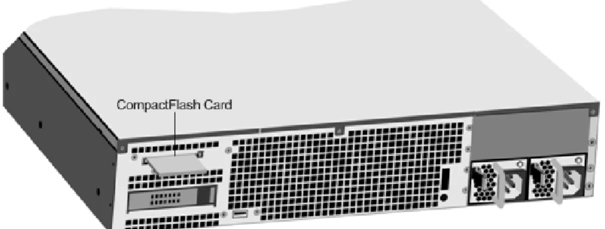
3. Locate the CompactFlash slot on the back panel of the appliance.
4. Disengage the CompactFlash by pushing the lever to the right of the CompactFlash slot. If necessary, use a pen or small screwdriver to push the lever in fully. Pull the existing flash card out of the slot.
Note: The illustration in the following figures might not represent the actual NetScaler appliance.
Figure 1. Removing the Existing CompactFlash Card 5. Insert the new flash card received from Citrix.
Important: When you insert the card, make sure that the arrow on top of the card is pointing toward the CompactFlash slot. Position the connector grid on the edge of the CompactFlash card to meet the matching connector pins inside the CompactFlash slot.
CompactFlash Card
Figure 2. Inserting the Replacement CompactFlash Card 6. Turn on the NetScaler appliance.
When the appliance starts, it no longer has the previous working configuration. Therefore, the appliance is reachable only through the default IP address of 192.168.100.1/16, or through the console port.
7. Perform the initial configuration of the appliance, as described in "Initial
Configuration." Log on to the default IP address by using a web browser, or connect to the serial console by using a console cable, to perform the initial configuration. 8. Upload a platform license and any optional feature licenses, including universal
licenses, to the NetScaler appliance. For more information, see the licensing chapter of the "Getting Started with Citrix NetScaler."
9. Once the correct NetScaler software version is loaded, you can restore the working configuration. Copy a previous version of the ns.conf file to the /nsconfig directory by using an SCP utility or by pasting the previous configuration into the /nsconfig/ns.conf file from the NetScaler command prompt. To load the new ns.conf file, restart the NetScaler appliance by entering the reboot command at the NetScaler command prompt.
29
Solid-State Drive
A solid-state drive (SSD) is a high-performance device that stores data in solid-state flash memory. The MPX solid-state drives contain the boot loader configuration file,
configuration file (ns.conf), licenses, and for some models, the NetScaler software and the user data.
The NetScaler software is stored on either the SSD or the CompactFlash card. The following MPX platforms store the NetScaler software on the SSD. The SSD is mounted as /flash.
• Citrix NetScaler MPX 5550 and MPX 5650
• Citrix NetScaler MPX 8200, MPX 8400, MPX 8600, and MPX 8800
• Citrix NetScaler MPX 11500, MPX 13500, MPX 14500, MPX 16500, MPX 18500, and MPX
20500
• Citrix NetScaler MPX 11515, MPX 11520, MPX 11530, MPX 11540, and MPX 11542 • Citrix NetScaler MPX 17500, MPX 19500, and MPX 21500
• Citrix NetScaler MPX 17550, MPX 19550, MPX 20550, and MPX 21550
• Citrix NetScaler MPX 22040, MPX 22060, MPX 22080, MPX 22100, and MPX 22120 • Citrix NetScaler MPX 24100 and MPX 24150
Note: On the MPX 5550/5650 and MPX 8200/8400/8600/8800 appliances, both /flash and /var are mounted from different partitions of the same SSD drive.
Replacing a Solid-State Drive
Note: These instructions apply to the Citrix NetScaler MPX 5550/5650, MPX 8200/8400/8600/8800, MPX 11500/13500/14500/16500/18500/20500, MPX 11515/11520/11530/11540/11542, MPX 17500/19500/21500, MPX
17550/19550/20550/21550, and MPX 22040/22060/22080/22100/22120 appliances. Replacement solid-state drives (SSDs) contain a pre-installed version of the NetScaler software and a generic configuration file (ns.conf), but they do not contain SSL-related certificates and keys, or custom boot settings. Configuration files and customized settings must be restored to a replacement drive from a backup storage location at the customer site, if available. The files to be restored might include:
• /flash/nsconfig/ns.conf: The current configuration file. • /flash/nsconfig/ZebOS.conf: The ZebOS configuration file. • /flash/nsconfig/license: The licenses for the NetScaler features.
• /flash/nsconfig/ssl: The SSL certificates and keys required for encrypting data to
clients or to backend servers.
• /nsconfig/rc.netscaler: Customer-specific boot operations (optional).
To replace a solid-state drive
1. At the NetScaler command prompt, exit to the shell prompt. Type: shell
2. Shut down the NetScaler appliance by typing the following command at the shell prompt:
shutdown –p now
3. Locate the SSD on the back panel of the appliance. Push the safety latch of the drive cover to the right or down, depending on the platform, while pulling out on the drive handle to disengage. Pull out the faulty drive.
Note: The illustration in the following figures might not represent the actual NetScaler appliance.
Figure 1. Removing the Existing Solid-State Drive
4. Verify that the replacement SSD is the correct type for the platform.
5. Pick up the new SSD, open the drive handle fully to the left or up, and insert the drive into the slot as far as possible. To seat the drive, close the handle flush with the rear of the appliance so that the drive locks securely into the slot.
Important: When you insert the drive, make sure that the Citrix product label is at the top if the drive is inserted horizontally or at the right if the drive is inserted vertically.
Figure 2. Inserting the Replacement Solid-State Drive
6. Turn on the NetScaler appliance. When the appliance starts, it no longer has the previous working configuration. Therefore, the appliance is reachable only through the Solid-State Drive
default IP address of 192.168.100.1/16, or through the console port. 7. Perform the initial configuration of the appliance, as described in "Initial
Configuration." Log on to the default IP address by using a web browser, or connect to the serial console by using a console cable, to perform the initial configuration. 8. Upload a platform license and any optional feature licenses, including universal
licenses, to the NetScaler appliance. For more information, see the licensing chapter of the "Getting Started with Citrix NetScaler."
9. Once the correct NetScaler software version is loaded, you can restore the working configuration. Copy a previous version of the ns.conf file to the /nsconfig directory by using an SCP utility or by pasting the previous configuration into the /nsconfig/ns.conf file from the NetScaler command prompt. To load the new ns.conf file, you must restart the NetScaler appliance by entering the reboot command at the NetScaler command prompt.
Solid-State Drive
Hard Disk Drive
A hard disk drive (HDD) stores logs and other data files. Files stored on the HDD include the newnslog files, dmesg and messages files, and any core/crash files. The HDD comes in various capacities, depending on the Citrix NetScaler platform. Hard drives are used for storing files required at runtime. An HDD is mounted as /var.
The following MPX platforms support HDD:
• Citrix NetScaler MPX 9700, MPX 10500, MPX 12500, and MPX 15500
• Citrix NetScaler MPX 11500, MPX 13500, MPX 14500, MPX 16500, MPX 18500, and MPX
20500
• Citrix NetScaler MPX 11515, MPX 11520, MPX 11530, MPX 11540, and MPX 11542 • Citrix NetScaler MPX 15000
• Citrix NetScaler MPX 17000
• Citrix NetScaler MPX 17500, MPX 19500, and MPX 21500
• Citrix NetScaler MPX 17550, MPX 19550, MPX 20550, and MPX 21550
• Citrix NetScaler MPX 22040, MPX 22060, MPX 22080, MPX 22100, and MPX 22120 • Citrix NetScaler MPX 24100 and MPX 24150
Replacing a Hard Disk Drive
A hard disk drive (HDD) stores log files and other user files. Collection of new log files begins upon boot-up with the new HDD. Product documentation can be downloaded from "MyCitrix.com" and reinstalled to the /var/netscaler/doc location.
To install a hard disk drive
1. At the NetScaler command prompt, exit to the shell prompt. Type: shell
2. Shut down the NetScaler appliance by typing one of the following commands at the shell prompt.
• On an MPX appliance, type:
shutdown –p now
• On a non-MPX appliance, type:
3. Locate the hard disk drive on the back panel of the appliance.
4. Verify that the replacement hard disk drive is the correct type for the NetScaler platform.
5. Disengage the hard disk drive by pushing the safety latch of the drive cover to the right or down, depending on the platform, while pulling out on the drive handle to
disengage. Pull out the faulty drive.
Note: The illustration in the following figures might not represent the actual NetScaler appliance.
Figure 1. Removing the Existing Hard Disk Drive
6. Pick up the new disk drive, open the drive handle fully to the left, and insert the new drive into the slot as far as possible. To seat the drive, close the handle flush with the rear of the appliance so that the hard drive locks securely into the slot.
Important: When you insert the drive, make sure that the Citrix product label is at the top.
Figure 2. Inserting the Replacement Hard Disk Drive
7. Turn on the NetScaler appliance. The appliance starts the NetScaler software and reads the configuration file from the CompactFlash card.
Hard Disk Drive
Direct Attach Cable
A direct attach cable (DAC) assembly is a high performance integrated duplex data link for bi-directional communication. The cable is compliant with the IPF MSA (SFF-8432) for mechanical form factor and SFP+ MSA for direct attach cables. The cable, which can be up to 5 meters long, is data-rate agnostic. Supporting speeds in excess of 10 Gbps, it is a cost-effective alternative to optical links (SFP+ transceivers and fiber optic cables.) The transceiver with DAC is hot-swappable. You can insert and remove the transceiver with the attached cable without shutting down the appliance. The Citrix NetScaler appliance supports only passive DAC.
Important:
• DAC is supported only on 10G ports. Do not insert a DAC into a 1G port.
• Do not attempt to unplug the integrated copper cable from the transceiver and insert a
fiber cable into the transceiver.
Installing a Direct Attach Cable
Note: The illustrations in the following figures are only for reference and might not represent the actual NetScaler appliance.
To install or remove a direct attach cable
1. To install the DAC, slide it into the 10G port on the appliance, as shown in the following figure. You will hear a click when the DAC properly fits into the port.
Figure 1. Inserting a DAC into the 10G port
2. To remove the DAC, pull the tab on the top of the DAC, and then pull the DAC out of the port, as shown in the following figure.
Figure 2. Removing a DAC from the 10G port Direct Attach Cable
Hardware Platforms
The various NetScaler hardware platforms offer a wide range of features, communication ports, and processing capacities. All the MPX platforms have multicore processors.
37
Citrix NetScaler 9010 FIPS
The Citrix NetScaler 9010 Federal Information Processing Standards (FIPS) appliance is a 2U appliance, with 1 single-core processor, and 2 GB of memory.
Note: The NetScaler nCore build is not supported on this hardware platform.
The following figure shows the front panel of the 9010 FIPS appliance with copper Ethernet ports.
Figure 1. Citrix NetScaler 9010 FIPS front panel, with copper Ethernet ports
The following figure shows the front panel of the 9010 FIPS appliance with fiber 1G SFP ports.
Figure 2. Citrix NetScaler 9010 FIPS front panel, with 1G SFP ports
The following components are visible on the front panel of the 9010 appliance:
• RS232 serial console port.
• Four ports, numbered 1/1, 1/2, 1/3, and 1/4 from left to right.
Note: The network port numbers on all appliances consist of two numbers separated by a forward slash. The first number is the port adapter slot number. The second number is the interface port number. Ports on appliances are numbered sequentially starting with 1.
Figure 3. Citrix NetScaler 9010 FIPS appliance, back panel
The following components are visible on the back panel of the 9010 FIPS appliance:
• Power switch, which turns off power to the appliance, just as if you were to unplug
both power supplies.
• Non-maskable interrupt (NMI) Button that is used at the request of Technical Support
and produces a core dump on the appliance. You must use a pen, pencil, or other pointed object to press this red button, which is recessed to prevent unintentional activation.
• Disable alarm button, which silences the alarm that the appliance sounds when it is
receiving power from only one of its power supplies. Press this button to prevent the power alarm from sounding when you have plugged the appliance into only one power outlet or when one power supply is malfunctioning and you wish to continue operating the appliance until it is repaired.
• Dual power supplies, each rated at 500 watts, 110-220 volts. You plug separate power
cords into the power supplies and connect them to separate wall sockets. The appliance functions properly with a single power supply; the extra power supply serves as a backup.
• 10/100BASE-T copper Ethernet port, numbered 0/1.
• Removable CompactFlash card that is used to store the NetScaler software. • Removable hard-disk drive that stores user data.
For information about installing the rails, rack mounting the hardware, and connecting the cables, see "Installing the Hardware."
For information about performing initial configuration of your appliance, see "Initial Configuration."
39
Citrix NetScaler 12000-10G
The Citrix NetScaler 12000-10G appliance is a 2U appliance, with 2 single-core processors, and 4 GB of memory.
Note: The NetScaler nCore build is not supported on this hardware platform. The following figure shows the front panel of the 12000-10G appliance.
Figure 1. Citrix 12000-10G appliance, front panel
The following components are visible on the front panel of the 12000-10G appliance:
• RS232 serial console port.
• Eight 1G SFP ports, numbered 1/1, 1/2, 1/3, 1/4, 1/5, 1/6, 1/7, and 1/8 from left to
right, and two XFP (10-Gigabit Small Form-Factor Pluggable) ports, numbered 1/9 and 1/10. When facing the bezel, the upper LEDs to the left of each optical 1G SFP port represent connectivity. They are lit and amber in color when active. The lower LEDs represent throughput. They are lit and green when active.
Note: The network port numbers on all appliances consist of two numbers separated by a forward slash. The first number is the port adapter slot number. The second number is the interface port number. Ports on appliances are numbered sequentially starting with 1.
Figure 2. Citrix NetScaler 12000-10G appliance, back panel
The following components are visible on the back panel of the 12000-10G appliance:
• Power switch, which turns off power to the appliance, just as if you were to unplug
both power supplies.
• Non-maskable interrupt (NMI) button, which signals the appliance to perform an orderly
shutdown after saving all files. You must use a pen, pencil, or other pointed object to press this button, which is located inside a small hole to prevent it being pressed accidentally.
• Disable alarm button, which silences the alarm that the appliance sounds when it is
receiving power from only one of its power supplies. Press this button to prevent the power alarm from sounding when you have plugged the appliance into only one power outlet or when one power supply is malfunctioning and you wish to continue operating the appliance until it is repaired.
• Dual power supplies, each rated at 500 watts, 110-220 volts. You plug separate power
cords into the power supplies and connect them to separate wall sockets. The appliance functions properly with a single power supply; the extra power supply serves as a backup.
• 10/100BASE-T copper Ethernet port, numbered 0/1.
• Removable CompactFlash card that is used to store the NetScaler software. • Removable hard-disk drive that stores user data.
For information about installing the rails, rack mounting the hardware, and connecting the cables, see "Installing the Hardware."
For information about performing initial configuration of your appliance, see "Initial Configuration."
41
Citrix NetScaler MPX 5500
The Citrix NetScaler MPX 5500 is a 1U appliance, with 1 dual-core processor, and 4 gigabytes (GB) of memory.
The following figure shows the front panel of the MPX 5500.
Figure 1. Citrix NetScaler MPX 5500, front panel
The MPX 5500 has the following ports:
• RS232 serial console port.
• Two 10/100/1000Base-T copper Ethernet management ports, numbered 0/1 and 0/2
from left to right. You can use these ports to connect directly to the appliance for system administration functions.
• Four 10/100/1000Base-T copper Ethernet ports numbered 1/1, 1/2, 1/3, and 1/4 from
left to right.
Note: The network port numbers on all appliances consist of two numbers separated by a forward slash. The first number is the port adapter slot number. The second number is the interface port number. Ports on appliances are numbered sequentially starting with 1.
The following figure shows the back panel of the MPX 5500.
Figure 2. Citrix NetScaler MPX 5500, back panel
The following components are visible on the back panel of the MPX 5500:
• Four GB removable CompactFlash card that is used to store the NetScaler software. • Power switch, which turns off power to the MPX 5500, just as if you were to unplug the
• Removable hard-disk drive (HDD) that is used to store user data. Appliances shipped
before February, 2012 store user data on a HDD. In appliances shipped after February, 2012, a solid-state drive replaces the HDD. Both types of drive have the same
functionality and support the same software releases.
• USB port (reserved for a future release).
• Non-maskable interrupt (NMI) Button that is used at the request of Technical Support
and produces a core dump on the NetScaler. You must use a pen, pencil, or other pointed object to press this red button, which is recessed to prevent unintentional activation.
• Power supply rated at 300 watts, 110-220 volts. The power-supply fan is designed to
turn on only when the internal temperature of the power supply reaches a certain value. You cannot see the fan turning on the back panel. What you can see is the fixed part of the fan that holds the spinning motor.
For information about installing the rails, rack mounting the hardware, and connecting the cables, see "Installing the Hardware."
For information about performing initial configuration of your appliance, see "Initial Configuration."
43
Citrix NetScaler MPX 5550 and MPX
5650
The Citrix NetScaler models MPX 5550 and MPX 5650 are 1U appliances. Each model has one quad-core processor and 8 gigabytes (GB) of memory.
The following figure shows the front panel of the MPX 5550/5650 appliance.
Figure 1. Citrix NetScaler MPX 5550/5650, front panel
Depending on the model, the appliance has the following ports:
• RS232 serial console port.
• Two 10/100/1000Base-T copper Ethernet management ports (RJ45), numbered 0/1 and
0/2 from left to right. The management port is used to connect directly to the appliance for system administration functions.
• Six 10/100/1000Base-T copper Ethernet ports numbered 1/1, 1/2, 1/3, 1/4, 1/5, and
1/6 from left to right.
The following figure shows the back panel of the MPX 5550/5650 appliance.
Figure 2. Citrix NetScaler MPX 5550/5650 appliance, back panel
The following components are visible on the back panel of the MPX 5550/5650 appliance:
• 160 GB removable solid-state drive, which is used to store the NetScaler software and
the user data.
• Power switch, which turns off power to the appliance, just as if you were to unplug the
• USB port (reserved for a future release).
• Non-maskable interrupt (NMI) button, which is used at the request of Technical Support
to produce a NetScaler core dump. You must use a pen, pencil, or other pointed object to press this red button, which is recessed to prevent unintentional activation.
• Single power supply, rated at 300 watts, 110-220 volts.
For information about installing the rails, rack mounting the hardware, and connecting the cables, see "Installing the Hardware."
For information about performing initial configuration of your appliance, see "Initial Configuration."
45
Citrix NetScaler MPX 7500 and MPX
9500
The Citrix NetScaler MPX 7500/9500 are 1U appliances, each with 1 quad-core processor, and 8 gigabytes (GB) of memory. The MPX 7500/9500 appliances are available in two port configurations: 8x10/100/1000Base-T copper Ethernet ports and 4x1G SFP +
4x10/100/1000Base-T copper Ethernet ports.
The following figure shows the front panel of the MPX 7500/9500 (8x10/100/1000Base-T copper Ethernet ports) appliances.
Figure 1. Citrix NetScaler MPX 7500/9500 (8x10/100/1000Base-T copper Ethernet ports), front panel
The following figure shows the front panel of the MPX 7500/9500 (4x1G SFP + 4x10/100/1000Base-T copper Ethernet ports) appliances.
Figure 2. Citrix NetScaler MPX 7500/9500 (4x1G SFP + 4x10/100/1000Base-T copper Ethernet ports), front panel
Depending on the model, the appliance has the following ports:
• RS232 serial console port.
• Two 10/100/1000Base-T copper Ethernet management ports, numbered 0/1 and 0/2
from left to right. These ports are used to connect directly to the appliance for system administration functions.
• MPX 7500/9500 (8x10/100/1000Base-T copper Ethernet ports). Eight
10/100/1000Base-T copper Ethernet ports numbered 1/1, 1/2, 1/3, and 1/4 on the top row from left to right, and 1/5, 1/6, 1/7, and 1/8 on the bottom row from left to right.
• MPX 7500/9500 (4x1G SFP + 4x10/100/1000Base-T copper Ethernet ports). Four
1-gigabit copper or fiber 1G SFP ports numbered 1/1, 1/2, 1/3, and 1/4 on the top row from left to right, and four 10/100/1000BASE-T copper Ethernet ports (RJ45) numbered 1/5, 1/6, 1/7, and 1/8 on the bottom row from left to right.
The following figure shows the back panel of the MPX 7500/9500 appliance.
Figure 3. Citrix NetScaler MPX 7500/9500, back panel
The following components are visible on the back panel of the MPX 7500/9500:
• Four-gigabyte removable CompactFlash card that is used to store the NetScaler
software.
• Power switch, which turns off power to the MPX 7500/9500, just as if you were to
unplug the power supply. Press the switch for five seconds to turn off the power.
• Removable hard-disk drive (HDD) that is used to store user data. Appliances shipped
before February, 2012 store user data on a HDD. In appliances shipped after February, 2012, a solid-state drive replaces the HDD. Both types of drive have the same
functionality and support the same software releases.
• USB port (reserved for a future release).
• Non-maskable interrupt (NMI) button that is used at the request of Technical Support
and produces a core dump on the appliance. You must use a pen, pencil, or other pointed object to press this red button, which is recessed to prevent unintentional activation.
• Disable alarm button. This button is functional only when the appliance has two power
supplies.
Press this button to stop the power alarm from sounding when you have plugged the MPX 7500/9500 into only one power outlet or when one power supply is malfunctioning and you want to continue operating the MPX 7500/9500 until it is repaired.
For information about installing the rails, rack mounting the hardware, and connecting the cables, see "Installing the Hardware."
For information about performing initial configuration of your appliance, see "Initial Configuration."
Citrix NetScaler MPX 7500 and MPX 9500
Citrix NetScaler MPX 8200, MPX 8400,
MPX 8600, and MPX 8800
The Citrix NetScaler models MPX 8200, MPX 8400, MPX 8600, and MPX 8800 are 1U
appliances. Each model has one quad-core processor and 32 gigabytes (GB) of memory. The MPX 8005/8015/8200/8400/8600/8800 appliances are available in two port configurations:
• Six 10/100/1000Base-T copper Ethernet ports and six 1G SFP ports
(6x10/100/1000Base-T copper Ethernet ports + 6x1G SFP)
• Six 10/100/1000Base-T copper Ethernet ports and two 10G SFP+ ports
(6x10/100/1000Base-T copper Ethernet ports + 2x10G SFP+)
The following figure shows the front panel of the MPX 8005/8015/8200/8400/8600/8800 (6x10/100/1000Base-T copper Ethernet ports + 6x1G SFP) appliance.
Figure 1. Citrix NetScaler MPX 8005/8015/8200/8400/8600/8800 (6x10/100/1000Base-T copper Ethernet ports + 6x1G SFP), front panel
The following figure shows the front panel of the MPX 8005/8015/8200/8400/8600/8800 (6x10/100/1000Base-T copper Ethernet ports + 2x10G SFP+) appliance.
Figure 2. Citrix NetScaler MPX 8005/8015/8200/8400/8600/8800 (6x10/100/1000Base-T copper Ethernet ports + 2x10G SFP+), front panel
Depending on the model, the appliance has the following ports:
• RS232 serial console port.
• One 10/100Base-T copper Ethernet Port (RJ45), also called LOM port. You can use this
software.
• One 10/100/1000Base-T copper Ethernet management port (RJ45), numbered 0/1. The
management port is used to connect directly to the appliance for system administration functions.
• Network Ports
• MPX 8005/8015/8200/8400/8600/8800 (6x10/100/1000Base-T copper Ethernet ports
+ 6x1G SFP). Six 10/100/1000BASE-T copper Ethernet ports (RJ45) numbered 1/1, 1/2, 1/3, 1/4, 1/5, and 1/6 on the top row from left to right, and six 1-gigabit copper or fiber 1G SFP ports numbered 1/7, 1/8, 1/9, 1/10, 1/11, and 1/12 on the bottom row from left to right.
• MPX 8005/8015/8200/8400/8600/8800 (6x10/100/1000Base-T copper Ethernet ports
+ 2x10G SFP+). Six 10/100/1000BASE-T copper Ethernet ports (RJ45) numbered 1/1, 1/2, 1/3, 1/4, 1/5, and 1/6 on the top row from left to right and two 10-gigabit SFP+ ports numbered 10/1 and 10/2 on the bottom row from left to right. The following figure shows the back panel of the MPX 8005/8015/8200/8400/8600/8800 appliance.
Figure 3. Citrix NetScaler MPX 8005/8015/8200/8400/8600/8800 appliance, back panel
The following components are visible on the back panel of the MPX 8005/8015/8200/8400/8600/8800 appliance:
• 256 GB removable solid-state drive, which is used to store the NetScaler software and
the user data.
• Power switch, which turns off power to the appliance, just as if you were to unplug the
power supply. Press the switch for five seconds to turn off the power.
• USB port (reserved for a future release).
• Non-maskable interrupt (NMI) button, which is used at the request of Technical Support
to produce a NetScaler core dump. You must use a pen, pencil, or other pointed object to press this red button, which is recessed to prevent unintentional activation.
• Disable alarm button, which is nonfunctional. This button is functional only if you install
a second power supply.
Press this button to stop the power alarm from sounding when you have plugged the appliance into only one power outlet or when one power supply is malfunctioning and you want to continue operating the appliance until it is repaired.
• Single power supply, rated at 450 watts, 110-220 volts.
Citrix NetScaler MPX 8200, MPX 8400, MPX 8600, and MPX 8800
For information about installing the rails, rack mounting the hardware, and connecting the cables, see "Installing the Hardware."
For information about performing initial configuration of your appliance, see "Initial Configuration."
51
Citrix NetScaler MPX 9700, MPX 10500,
MPX 12500, and MPX 15500
The Citrix NetScaler MPX 9700/10500/12500/15500 are 2U appliances, each with 2 quad-core processors, and 16 gigabytes (GB) of memory. All these appliances are also available in a 10G model and a FIPS model.
The following figure shows the front panel of the MPX 9700/10500/12500/15500.
Figure 1. Citrix NetScaler MPX 9700/10500/12500/15500, front panel
The following figure shows the front panel of the MPX 9700/10500/12500/15500 10G.
Figure 2. Citrix NetScaler MPX 9700/10500/12500/15500 10G, front panel
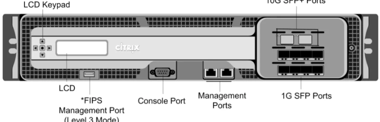
Figure 3. Citrix NetScaler MPX 9700/10500/12500/15500 FIPS, front panel
*The FIPS Management Port (Level 3 Mode) is reserved for a future release.
Caution: Do not insert a USB device into the FIPS Management Port. This will cause the FIPS card to fail.
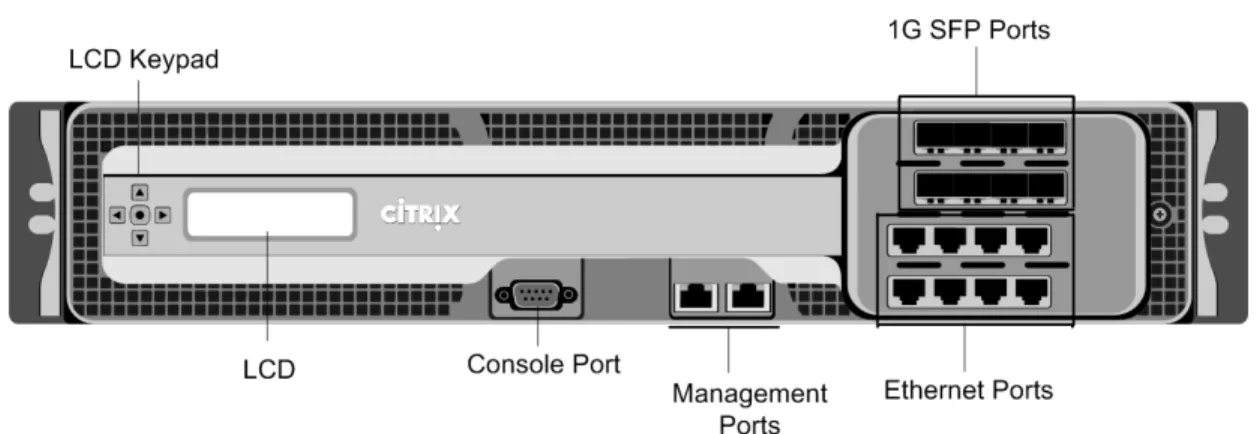
Depending on the model, the appliance has the following ports:
• FIPS Management Port (reserved for a future release). • RS232 serial Console Port.
• Two 10/100/1000Base-T copper Ethernet Management Ports (RJ45), numbered 0/1 and
0/2 from left to right. These ports are used to connect directly to the appliance for system administration functions.
• Network Ports
• MPX 9700/10500/12500/15500. Eight copper or fiber 1G SFP ports numbered 1/1,
1/2, 1/3, and 1/4 on the first row from left to right, and 1/5, 1/6, 1/7, and 1/8 on the second row from left to right. Eight 10/100/1000BASE-T copper Ethernet Ports (RJ45) numbered 1/9, 1/10, 1/11, and 1/12 on the third row from left to right, and 1/13, 1/14, 1/15, and 1/16 on the fourth row from left to right.
• MPX 9700/10500/12500/15500 10G and MPX 9700/10500/12500/15000 FIPS. Two
10G SFP+ Ports numbered 10/1 and 10/2 on the top row, eight 1-gigabit copper or fiber 1G SFP Ports numbered 1/1, 1/2, 1/3, and 1/4 on the middle row from left to right, and 1/5, 1/6, 1/7, and 1/8 on the bottom row from left to right.
Important: The 10-gigabit ports on this appliance are labeled 10/1 and 10/2.
The following figure shows the back panel of the MPX 9700/10500/12500/15500 appliances, including the 10G model and FIPS model.
Figure 4. Citrix NetScaler MPX 9700/10500/12500/15500, MPX 9700/10500/12500/15500 FIPS, and MPX 9700/10500/12500/15500 10G, back panel
*The USB Port is reserved for a future release.
The following components are visible on the back panel of the MPX 9700/10500/12500/15500, including the 10G model and FIPS model:
• Four GB removable CompactFlash Card that is used to store the NetScaler software. • Power Switch, which turns off power to the appliance, just as if you were to unplug the
power supply. Press the switch for five seconds to turn off the power.
• Removable Hard Disk Drive that is used to store user data. • USB Port (reserved for a future release).
• Non-maskable interrupt (NMI) Button that is used at the request of Technical Support
and produces a core dump on the NetScaler. You must use a pen, pencil, or other pointed object to press this red button, which is recessed to prevent unintentional activation.
• Disable Alarm Button. This button is functional only when the appliance has two power
supplies.
Press this button to stop the power alarm from sounding when you have plugged the appliance into only one power outlet or when one power supply is malfunctioning and you want to continue operating the appliance until it is repaired.
• Dual Power Supplies, each rated at 450 watts, 110-220 volts.
For information about installing the rails, rack mounting the hardware, and connecting the cables, see "Installing the Hardware."
For information about performing initial configuration of your appliance, see "Initial Configuration."
Citrix NetScaler MPX 9700, MPX 10500, MPX 12500, and MPX 15500
Citrix NetScaler MPX 11500, MPX 13500,
MPX 14500, MPX 16500, MPX 18500,
and MPX 20500
The Citrix NetScaler models MPX 11500/13500/14500/16500/18500/20500 are 2U
appliances. Each model has two 6-core processors for a total of 12 physical cores (24 cores with hyper-threading), and 48 gigabytes (GB) of memory.
The following figure shows the front panel of the MPX 11500/13500/14500/16500/18500/20500 appliance.
Figure 1. Citrix NetScaler MPX 11500/13500/14500/16500/18500/20500 appliance, front panel
The MPX 11500/13500/14500/16500/18500/20500 appliances have the following ports:
• 10/100Base-T copper Ethernet Port (RJ45), also called LOM port. You can use this port
to remotely monitor and manage the appliance independently of the NetScaler software.
Note: The LEDs on the LOM port are not operational by design.
• RS232 serial console port.
• Two 10/100/1000Base-T copper Ethernet management ports (RJ45), numbered 0/1 and
0/2 from left to right. These ports are used to connect directly to the appliance for system administration functions.
• Eight 1G SFP ports numbered 1/1, 1/2, 1/3, 1/4 from top to bottom in the first column,
• Four 10G SFP+ ports numbered 10/1 and 10/2 from top to bottom in the first column,
and 10/3 and 10/4 from top to bottom in the second column. The following figure shows the back panel of the MPX
11500/13500/14500/16500/18500/20500 appliance.
Figure 2. Citrix NetScaler MPX 11500/13500/14500/16500/18500/20500 appliance, back panel
The following components are visible on the back panel of the MPX 11500/13500/14500/16500/18500/20500 appliance:
• 160 GB removable solid-state drive that is used to store the NetScaler software. • USB port (reserved for a future release).
• Power switch, which turns off power to the appliance, just as if you were to unplug the
power supply. Press the switch for five seconds to turn off the power.
• Non-maskable interrupt (NMI) Button that is used at the request of Technical Support
and produces a core dump on the NetScaler. You must use a pen, pencil, or other pointed object to press this red button, which is recessed to prevent unintentional activation.
• Two removable hard-disk drives that are used to store user data.
• Disable alarm button. This button is functional only when the appliance has two power
supplies.
Press this button to stop the power alarm from sounding when you have plugged the appliance into only one power outlet or when one power supply is malfunctioning and you want to continue operating the appliance until it is repaired.
• Dual power supplies, each rated at 650 watts, 110-220 volts.
For information about installing the rails, rack mounting the hardware, and connecting the cables, see "Installing the Hardware."
For information about performing initial configuration of your appliance, see "Initial Configuration."
Citrix NetScaler MPX 11500,MPX 13500,MPX 14500,MPX 16500,MPX 18500, andMPX 20500
Citrix NetScaler MPX 11515, MPX 11520,
MPX 11530, MPX 11540, and MPX
11542
The Citrix NetScaler models MPX 11515/11520/11530/11540/11542 are 2U appliances. Each model has two 6-core processors for a total of 12 physical cores (24 cores with
hyper-threading), and 48 gigabytes (GB) of memory.
The following figure shows the front panel of the MPX 11515/11520/11530/11540/11542 appliance.
Figure 1. Citrix NetScaler MPX 11515/11520/11530/11540/11542 appliance, front panel The MPX 11515/11520/11530/11540/11542 appliances have the following ports:
• RS232 serial console port.
• 10/100Base-T copper Ethernet Port (RJ45), also called LOM port. You can use this port
to remotely monitor and manage the appliance independently of the NetScaler software.
Note: The LEDs on the LOM port are not operational by design.
• Two 10/100/1000Base-T copper Ethernet management ports (RJ45), numbered 0/1 and
0/2 from left to right. These ports are used to connect directly to the appliance for system administration functions.
• Eight 10G SFP+ ports and four copper or fiber 1G SFP ports.
The following figure shows the back panel of the MPX 11515/11520/11530/11540/11542 appliance.