The final publication is available at Springer via http://dx.doi.org/10.1007/s11107-015-0488-0
Routing, Modulation, Spectrum and Launch Power Assignment to
Maximize the Traffic Throughput of a Nonlinear Optical Mesh Network
David J. Ives · Polina Bayvel · Seb J. Savory
Received: date / Accepted: date
Abstract We investigate the optimization of routing, mod-ulation format adaptation, spectral and launch power as-signment as a means of improving the utilization of limited network resources and increasing the network throughput. We consider a transparent optical network operating in the nonlinear transmission regime and using the latest software adapted coherent optical techniques. We separate the prob-lem into one of routing, modulation adaption and channel assignment, followed by channel spectral assignment, and launch power allocation. It is shown, for three test networks, that the launch power allocation and channel spectral assign-ment can improve the transmission SNR margin over the fixed modulation, fixed power, fully load link worst case by approximately 3-4 dB. This increase in SNR margin can be utilized through modulation format adaption to increase the overall network throughput. This paper highlights that in-creased gains in network throughput can be achieved in non-linear impaired networks when individual transmitter spec-tral assignment and launch power is optimized to minimize the nonlinear interference.
This work was supported by the UK Engineering and Physical Sciences Research Council, through the Centre for Doctoral Training in Photon-ics Systems Development, EP/G037256/1 and programme grant UN-LOC, EP/J017582/1, and The Royal Academy of Engineering / The Leverhulme Trust.
D. Ives
Department of Electronic and Electrical Engineering, University College London, London, UK.
E-mail: [email protected] P. Bayvel
Department of Electronic and Electrical Engineering, University College London, London, UK.
E-mail: [email protected] S. Savory
Department of Electronic and Electrical Engineering, University College London, London, UK.
E-mail: [email protected]
Keywords Off-line Routing·Nonlinear Impairments· Modulation Adaption·Power Optimization
1 Introduction
Optical fibre mesh networks connecting re-configurable op-tical add drop multiplexers, ROADMs, form the backbone of modern communications and the internet. These networks utilize wavelength routing to transparently connect source and destination nodes. Traditionally the transmitter-receiver pairs are designed to operate error-free in the worst case, for transmission between the furthest spaced nodes so that any route reconfiguration can be accommodated. This leads to over provisioning of resource with large margins for the ma-jority of signals. With the development of software-defined transceivers[1–3] the transmitter can be re-configured allow-ing the transmission parameters to be adapted to the selected physical route. Given the continuing increases in network traffic and this ability to configure the transmitter parame-ters the physical network resources of bandwidth and power can be used more efficiently.
In this paper we consider a fixed network infrastruc-ture with a physical topology of nodes, consisting of ROADMs and transceivers, connected by edges formed of dispersion uncompensated fibre pairs. Each fibre edge is formed in fixed spans with Erbium doped fibre am-plifiers compensating for the loss of each span. Polariza-tion multiplexed-mQAM modulated signals are transmitted on a fixed DWDM grid and routed transparently without wavelength conversion. A nonlinear quality of transmission model estimates the SNR of each signal while taking the in-dividual launch powers into account. We use the model to optimizing the routing, modulation format, spectral assign-ment and launch power with the primary aim of maximizing the network data throughput. We extend our earlier work[4]
by assessing the applicability of the optimization technique to more network topologies with different scale.
In the area of optical network optimization mixed line rates utilizing OOK, DQPSK and PM-QPSK signals with impairment-aware routing to reduce capital expenditure have been used[5], although this type of analysis makes it difficult to link cost savings with potential increases in traffic throughput. The recent development of elastic optical net-works[6, 7] has improved spectral efficiency, however in this paper we only consider a fixed DWDM grid, leaving the op-tion of utilizing the potential gain of “elasticity” in future work. The extension of elastic optical networks to include modulation format adaptation based on the quality of trans-mission or reach has also further improved overall spectral efficiency[8–10]. In this paper we use modulation format adaptation, based on the physical link properties, specifi-cally, the nonlinear quality of transmission.
In traditional dispersion managed OOK systems, FWM is the dominant nonlinear impairment. It has been shown that for a sparsely populated spectrum by careful alloca-tion of the channel centre frequency away from a regular grid the FWM components can be generated away from the transmission signals eliminating the interference at the ex-pense of an increase in bandwidth usage[11]. Adhya et al [12] considered the FWM in the design of a logical network on the physical layer and equalised the SNR across channels by routing longer paths to the outer parts of the spectrum to reduce the number of interfering FWM components. In this work we consider the new high dispersion paradigm such that FWM is considerably reduced. We consider a situation where the spectral bandwidth is heavily occupied and the use of coherent transmission formats lead to nonlinear inter-ference that is dominated by SPM and XPM
Other authors have included nonlinear impairments in the routing and spectral assignment algorithms by includ-ing a nonlinearity constraint[13] and through a power opti-mized reach constraint[14]. Here, we wish to take advantage of the results presented in[15] which indicate that the cor-rect routing and spectral assignment can lead to improved SNR and throughput. We include a nonlinear weight in the optimization objective function to initially group highly in-terfering channels so that highly inin-terfering channels can be subsequently given well separated spectral assignments. Fi-nally individual transmitter launch powers were optimized, to maximize the reach[14] while in [16] an altruistic mini-mization of transmitter power was found to benefit the wider network. Here we take a global view of the network and ad-just individual transmitter powers to equally distribute and maximize the available SNR margin above error free trans-mission.
In Sect. 2, we describe the nonlinear quality of transmis-sion model used to assess the physical layer performance and allow adjustment of the individual transmitter launch
powers. In Sect. 3 we describe the network physical layer parameters and test topologies used. This is followed by a description of the routing, modulation and channel assign-ment algorithm that is used to maximise the network data throuhput based on an ILP formulation in Sect. 4.1. The spectral assignment of the channels and the adjustment of individual transmitter launch power to maximise the SNR margin is described in Sect. 4.2. The final sections describe the application of the algorithms to a selection of real net-work topologies and demonstrate the gains in netnet-work data throughput that can be achieved.
2 Physical Layer Nonlinear Propagation Model
For the optimization considered in this paper a simple phys-ical layer impairment model is required to allow rapid com-putation of the quality of signal transmission. The assumed signals formats are restricted to polarization-multiplexed co-herent modulation schemes such that the linear impairments can be ideally and adaptively compensated in the coherent receiver. Signal degradation is caused by the combination of the accumulated ASE noise from the erbium doped fibre amplifiers, EDFAs, in the optical path and the accumulated nonlinear interference between co-propagating signals. For optical fibre infrastructure, that is dispersion uncompensated the Gaussian noise, GN, model has been assumed for the purpose of predicting and quantifying the nonlinear inter-ference as a source of additive Gaussian noise[17–20]1. In this case the symbol SNR,SNRi, of theithsignal is given by
SNRi=
pi
nASE,i+nNLI,i
(1)
wherepiis the received signal power,nASE,iis the ASE noise
power andnNLI,i is the nonlinear interference noise power
within the receiver filter bandwidth, all on theithsignal. As the transmission loss of each span is fully compen-sated by the EDFA gain, the received signal power is equal to the transmitter launch power and the ASE noise power is given by [24, 25] nASE,i=Ns10 NF 10hνR10 Aspan 10 (2)
whereNF is the amplifier noise figure (dB),his Planck’s constant (6.626×10⁻³⁴J.s),νis the channel carrier optical frequency (193.5×10¹² Hz),Ris the symbol rate (Baud),
1 Recently a number of authors[21–23] have proposed correction
terms to the GN model to overcome some of the GN models short-comings particularly in the early spans of a transmission link where the accumulated chromatic dispersion is low. These correction terms reduce the expected nonlinear interference noise power for the modu-lation formats considered in this paper. We thus utilize the simpler GN model here under the assumption that it conservatively estimates the nonlinear interference noise and thus allows for robust network opti-mization.
Aspan is the loss of a single fibre span (dB) and Ns is the
number of spans in the route. This approximation for the ASE noise assumes that the gain of the amplifier is large and that any reduction in gain needed to match the span loss is achieved using a following variable attenuator. The effective noise bandwidth used is equal to the symbol rateRunder the assumption that the overall noise spectrum is white, domi-nated by ASE, and the receiver implements an ideal matched filter to maximize the SNR.
The Kerr effect leads to nonlinear interference noise that can be considered as self phase modulation, SPM, for non-linear interference caused solely within theithsignal, cross phase modulation, XPM, for interference on the ith signal caused by the jth signal and four wave mixing, FWM, for interference caused by the interaction of multiple signals. For well spaced signals, such that there is negligible cross-talk of the nonlinear interference noise between signals, and under the assumption that the nonlinear interference noise due to FWM can be ignored as insignificant2[18] then the nonlinear interference noise,nNLI,i on the ithsignal due to
SPM and XPM can be written as [15, 26, 27]
nNLI,i=Nspi
∑
jXi,jp2j (3)
where Ns is the number of spans over which the
nonlin-ear interference accumulates,pare the signal launch pow-ers and the summation j is over all interacting signals.Xi,j
is a single-span efficiency factor for the nonlinear interfer-ence noise on theithsignal caused by thejthsignal such that Xi,j,i̸=jis a XPM factor andXi,iis a SPM factor. The
non-linear efficiency factor was calculated by numerical integra-tion of the GN reference equaintegra-tion (1) in [28].Xi,jis a
func-tion ofνi−νjwhereνiandνjare the carrier frequencies
of theithandjthsignals leading to just 80 unique values that were pre-computed. It is assumed in this work that nonlin-ear interference from multiple spans adds incoherently[29] and also that the SPM has been ideally compensated using digital back propagation[30] such thatXi,i=0.
3 Network Physical Topology
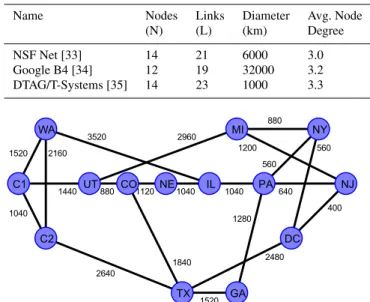
The routing, modulation, spectral assignment and launch power optimization algorithm was tested on three network topologies as described in Table 1 and shown in Fig. 1, Fig. 2 and Fig. 3. The link lengths,Z (km), were calculated from the great circle distance between the nodes,ZGC(km), and a
fibre routing factor using [31]
2 For the DWDM channel spacing and signal symbol rate used in
this work the assumption of well spaced signals and insignificant FWM was found to lead to an error of only≈0.31% on the value ofXmused in equation (7).
Table 1 Details of the network topologies tested.
Name Nodes Links Diameter Avg. Node
(N) (L) (km) Degree NSF Net [33] 14 21 6000 3.0 Google B4 [34] 12 19 32000 3.2 DTAG/T-Systems [35] 14 23 1000 3.3 1520 1040 2160 1440 880 1120 1040 1040 2640 1520 1840 640 560 880 560 400 1200 2480 1280 3520 2960 WA C1 C2 UT CO NE IL PA NJ TX GA DC MI NY
Fig. 1 The 14-node, 21-link NSF mesh topology showing the link lengths used in (km). 2320 2560 320 1120 1200 3840 8320 8560 480 480 880 16480 15440 1680 2080 4560 2640 1600 720 A B C D J I H E G F K L
Fig. 2 The 12-node, 19-link Google B4 mesh topology showing the link lengths used in (km).
Z =1.50ZGC, ZGC≤1000 km =1500, 1000 km≤ZGC≤1200 km =1.25ZGC, ZGC≥1200 km (4)
The great circle distance between the nodes was calcu-lated from the latitude and longitude of the nodes using the Haversine formula [32]. ZGC=2Re· arcsin (√ sin2 ( ϕ1−ϕ2 2 )
+cos(ϕ1)cos(ϕ2)sin2 (
λ1−λ2
2 ))
(5) whereReis the radius of the earth taken as 6367 km andϕ
andλ are the latitude and longitude of the nodes. The link lengths were rounded to the nearest 80 km, the span length used in this work.
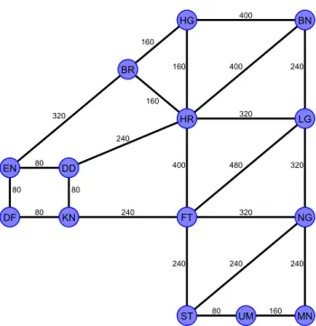
400 240 400 160 160 160 320 320 480 320 400 240 240 320 240 240 240 80 80 80 80 160 80 BN HG BR LG HR DD EN NG FT KN DF MN UM ST
Fig. 3 The 14-node, 23-link DTAG/T-Systems National core network showing the link lengths used in (km).
Each link was assumed to be a fibre pair con-sisting of uncompensated, single mode fibre in 80 km spans with attenuation 0.22 dB.km−1, chromatic dis-persion 16.7 ps.nm−1.km−1 and nonlinear coefficient 1.3 W−1.km−1. The loss of each span was assumed to be ideally compensated by an EDFA with a noise figure of 5 dB. Each fibre was assumed to support 80 DWDM chan-nels on a 50 GHz fixed grid, each transmitting 28 GBaud signals with a root raised cosine spectral shape (roll off 0.5). The ROADM nodes were assumed to be ideal, and thus not contributing to the overall noise.
The required symbol SNR for error free data transmis-sion is shown in Table 2 for the various PM-mQAM mod-ulation formats considered. The required symbol SNR was calculated as the theoretical symbol SNR required to give a pre-FEC BER of 4×10⁻³in the presence of AWGN[36, 37]. Table 2 also shows the error free data transmission rate based on the 28 GBaud symbol rate that includes a 12% overhead for FEC and signal framing.
In order to optimize the traffic throughput of a network the starting point is the assumed traffic demand profile. In this work it was assumed that the traffic demand profile was uniform and equal between all node pairs such that a normal-ized traffic matrix,T, was defined with the traffic between source node,s, and destination node,d, given byTs,das
Ts,d=
{ 1
N(N−1) fors̸=d
0 fors=d (6)
whereNis the number of nodes.
Table 2 Required symbol SNR to achieve a pre-FEC BER of 4×10⁻³
and error free data rate, at 28 GBaud including overhead, for various PM-mQAM formats.
Format Bit Data Required
Acronym Loading Rate Symbol SNR
(b.Sym−1) (Gb.s−1) (dB) PM-BPSK 2 50 5.5 PM-QPSK 4 100 8.5 PM-8QAM 6 150 12.5 PM-16QAM 8 200 15.1 PM-32QAM 10 250 18.1 PM-64QAM 12 300 21.1 PM-128QAM 14 350 23.9 PM-256QAM 16 400 26.8
4 Network Transmission Optimization
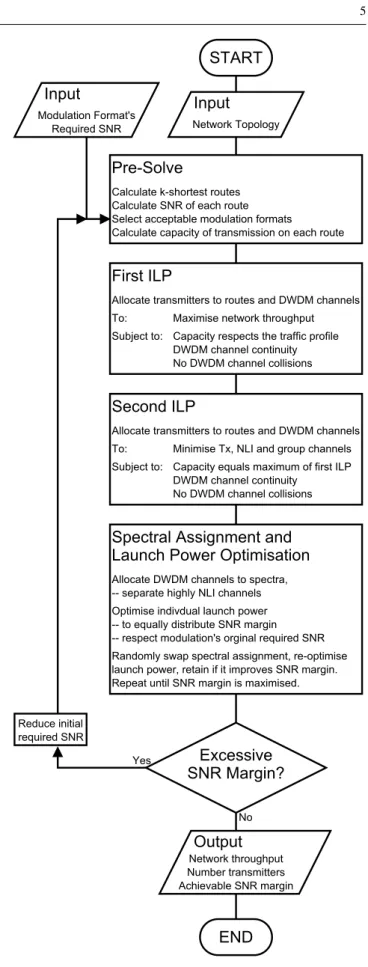
In this section we describe the process by which the routing, channel assignment and transmitter parameters are adapted with the primary aim to maximize the network throughput and secondary aims to minimize the number of transceivers and maximize the available SNR margin above that required for error free transmission. An overall flow diagram illus-trating the process is shown in Fig. 4.
A pre-solve stage calculates the k-shortest routes be-tween each node pair, the SNR of each route and selects suitable modulation formats. Next a mixed integer linear program, MILP, is used to allocate transmitters to routes and DWDM channels to maximize the network throughput within the constraint of the traffic profile and physical re-sources. Having found the maximum network throughput the MILP is resolved with the secondary objective to mimize the number of transmitters, minmimize nonlinear in-terference and group highly interfering DWDM channels. These processes are described in detail in Sect. 4.1.
Given a network solution with transmitters allocated to routes and DWDM channels the next step is to optimize in-dividual launch powers and assign spectrum to each DWDM channel. The highly interfering channels have been grouped to low DWDM channel numbers so the DWDM channels are not allocated sequential spectral slots but are dispersed to reduce the nonlinear interference. The process of assigning DWDM channels to physical spectrum and optimizing indi-vidual launch powers is described in Sect. 4.2. The aim of this process is to maximize the available SNR margin given a network solution developed in Sect. 4.1.
Where the process of spectral assignment and launch power optimization reveals a large SNR margin the initial pre-solve stage is re-calculated on the temporary assump-tion that the modulaassump-tion formats required SNR can be re-duced, allowing higher order modulation on some routes than would initially have been allowed. The MILP, launch power optimization and spectral assignment are repeated to obtain new network solutions with potentially higher
throughput but lower SNR margin. Provided the SNR mar-gin is>0 the new network solution was deemed viable.
4.1 Static Routing, Modulation and Channel Assignment This section describes the approach used to optimize the routing, modulation format and channel assignment when the launch power and nonlinear interference are pre-calculated and fixed. We leave the spectral assignment of the channels and launch power allocation to Sect. 4.2. The primary aim of this optimization was to maximize the net-work traffic throughput, with a secondary aim of minimiz-ing the number of transmitters and minimizminimiz-ing the nonlin-ear interference noise for robust transmission. In order to remove the launch power consideration from this stage of the optimization the launch power was pre-optimized by set-ting a constant and equal optimized power and similar to the LOGON[38] strategy all the DWDM channels were consid-ered fully occupied with a constant power. This assumption removes the exact routing and DWDM channel allocation from the SNR estimation, decoupling the choice of modu-lation format from the routing and channel allocation. The symbol SNR of all the channels over a route was taken as the minimum SNR,SNRM, on the worst case, central, channel such that
SNRM= p0 NsnASE+NsXmp30
(7)
where p0 is the equal launch power of all the channels, Ns is the number of fibre spans the signal traverses,nASE
is the ASE noise accumulated in a single fibre span and Xm=maxj∑iXi,j, is the maximum nonlinear interference
efficiency for a fully loaded single span. The launch power, p0, is optimized to maximize the SNR of equation (7). The optimum launch power is independent of the route length since both noise terms depend linearly on the number of spans here. For the fibre, EDFA and signal parameters used, the ASE noise accumulated from each fibre span,nASE, was
0.00065 mW, and the maximum nonlinear interference fac-tor,Xm, was 0.00067 mW−2such that the optimum launch
power was 0.79 mW (-1.0 dBm). The worst case SNR, SNRM, of each route can be simply calculated given the number of fibre spans traversed.
To solve the routing and spectral allocation problem there are two widespread integer linear programming, ILP, formulations; those based on flow and those based on routes [39, 40]. Since the transmission SNR for a given connection depends on the overall route, and not on individual links, the modulation format will be dependent and the route-based ILP formulation is more appropriate here.
As a preliminary stage to solving the ILP problem, first the k-shortest routes[41], k=25, between each source-destination node pair were calculated and theSNRMof each
START
Input
Network TopologyInput
Modulation Format's Required SNRPre-Solve
Calculate k-shortest routes Calculate SNR of each route Select acceptable modulation formats
Calculate capacity of transmission on each route
First ILP
Allocate transmitters to routes and DWDM channels To: Maximise network throughput Subject to: Capacity respects the traffic profile
DWDM channel continuity No DWDM channel collisions
Second ILP
Allocate transmitters to routes and DWDM channels To: Minimise Tx, NLI and group channels Subject to: Capacity equals maximum of first ILP
DWDM channel continuity No DWDM channel collisions
Spectral Assignment and
Launch Power Optimisation
Allocate DWDM channels to spectra, -- separate highly NLI channels Optimise indivdual launch power -- to equally distribute SNR margin -- respect modulation's orginal required SNR Randomly swap spectral assignment, re-optimise launch power, retain if it improves SNR margin. Repeat until SNR margin is maximised.
Excessive
SNR Margin?
No YesOutput
Network throughput Number transmitters Achievable SNR marginEND
Reduce initial required SNRFig. 4 Flow diagram to illustrate the overall network optimisation pro-cess.
route was calculated based on the number of fibre spans in the route as equation (7) assuming all DWDM channels are occupied with a signal at the optimized power. The modu-lation formats where the route SNR exceeds the modumodu-lation formats required SNR were chosen for each route from the modulation formats listed in Table 2 and the capacity of each route with each modulation format was calculated.
Next, the allocation of DWDM channels to routes was optimized as a mixed integer linear program, MILP, in order to maximize the traffic throughput. It should be noted that the traffic matrix is symmetric,Ts,d=Td,s, and the network
is symmetric with fibre pairs, so as is customary we reduced the problem by solving ford>sonly. In order to describe the MILP problem the following notation was used
Constants:
– N: number of nodes, – L: number of links,
– K: number of shortest routes, – W: number of DWDM channels,
– M: number of modulation formats available over a given routers,d,k,
Parameters:
– s,d: the source and destination nodes∈ {1,2, . . . ,N}, – l: a link∈ {1,2, . . . ,L},
– k: a shortest route∈ {1,2, . . . ,K}, – w: a DWDM channel∈ {1,2, . . . ,W}, – m: a modulation format∈ {1,2, . . . ,M},
– Ts,d: the normalized traffic demand between source, s,
and destination ,d,
– rs,d,k: thekthshortest route between source,s, and
desti-nation ,d,
– δsL,d,k,l: is set to 1 if routers,d,ktraverses linkl, 0
other-wise,
– SNRMs,d,k: the worst case symbol SNR for transmission over routers,d,k,
– Cs,d,k,m: the capacity of transmission over route rs,d,k
with modulation format,m.
– SNRRs,d,k,m: the required symbol SNR for error free trans-mission over routers,d,kat the capacityCs,d,k,m,
Variables:
– c: the total throughput of the network, a multiplying fac-tor to the normalized traffic matrixTto define the actual traffic demand,
– δsF,d,k,m,w: is 1 if a transceiver for routers,d,kuses
modu-lation format,m, and DWDM channelw, 0 otherwise. The aim is to optimizecas a continuous variable and δF
s,d,k,m,was binary variables, so that
cmax= max c,δsF,d,k,m,w
c (8)
subject to the total capacity between all source,s, and desti-nation,d, nodes exceeding the demand
∑
w∑
m∑
kδF
s,d,k,m,wCs,d,k,m−cTs,d>=0 ∀ s,d>s. (9)
and the number of signals occupying DWDM channel,w, in any link,l, does not exceed 1,
∑
m
∑
k∑
s d∑
>sδF
s,d,k,m,wδsL,d,k,l<=1 ∀ l,w. (10)
The ILP optimization was solved using IBM CPLEX® and for the results presented in this paper the computation took typically a few hours on a dual quad core computer with 16 threads running at 2.3 GHz.
Given that the maximum network throughput cmax has
been calculated the MILP was re-solved with the secondary objective to group highly interfering channels, for later sep-aration, while minimizing the total number of transmitters and the overall nonlinear interference. OptimizeδsF,d,k,m,was binary variables to min δF s,d,k,m,w
∑
w∑
m∑
k∑
s d∑
>s δF s,d,k,m,w· 1000+ Zs,d,k 10000 ( SNRRs,d,k,m SNRMs,d,k )2( w 10+100 ) (11)subject to the constraints of equations (9) and (10) where chas been replaced bycmax. The large constant in the
ob-jective function ensures that the minimum number of trans-mitters are used. The term SNR
R s,d,k,m
SNRM s,d,k
is the ratio of the mod-ulation formats’ required SNR to the basic SNR of the route used in the routing stage, the worst case where all channels are occupied. This ratio is related to the expected transmitter power thus the square multiplied by the route lengthZs,d,k denotes the channels likelihood to cause
non-linear interference. By dividingZs,d,k by 10000 a constant
of the order of the maximum of Zs,d,k the weight term Zs,d,k 10000 ( SNRR s,d,k,m SNRM s,d,k )2
is of order 1. By weighting the objective function with the channel number, more highly interfering signals will be placed in the lowest available channel num-ber, thus grouping them together. The constant added to the channel weight ensures that nonlinear interference is always more weighted than channel number. The objective function weight increases by order 1000 for additional transmitters, order<100 for nonlinear interference and order <10 for higher channel numbers. So this objective function tries to, in order of priority, minimize the number of transmitters, then minimize the nonlinear interference and finally group highly interfering signals. There is still some considerable scope to improve this objective function to more closely achieve these stated aims.
4.2 Launch Power and Spectral Assignment
The nonlinear interference noise equation (3) was developed with point-to-point links in mind however it applies equally well to mesh networks. The ith or jth transmitter-receiver pair each corresponds to one active{s,d,k,m,w}connection between source,s, destination,d, by thekth shortest route, with modulation format,m, and utilizing wavelength chan-nelwwhereδF
s,d,k,m,w=1. For theithtransmitter in a mesh
network the ASE noise,nASE,iis given by
nASE,i=10 NF 10 hνR
∑
l [ δL i,lNs,l10 Aspan 10 ] (12)where Ns,l is the number of spans in link l and δiL,l is 1
if the signal from theithtransmitter-receiver pair traverses link l, zero otherwise. Similarly the nonlinear interference is given by a summation of the nonlinear interference accu-mulated on theithtransmitted signal as it traverses each link on its route, thus the accumulated nonlinear efficiency,XiA,j, is given by XiA,j=
∑
l [ δL i,lδLj,lNs,lX(|νi−νj|) ] (13)whereX(∆ν) is the single span efficiency for the nonlin-ear interference between signals spaced by a frequency,∆ν. Given that the ithtransmitter-receiver pair requires a sym-bol SNR,SNRRi, with an overall marginSNRmarginthen the
launch powers, p should be minimized to achieve a sym-bol SNR ofSNRmarginSNRR. The launch powers were
it-eratively optimized to achieve the required SNR and were initialized based on ASE noise alone using
pi=SNRmarginSNRRi nASE,i. (14)
For a given network state with launch powers,pthe SNR of theithsignal is given by,
SNRi= pi nASE,i+pi∑j ( XiA,jp2j ). (15)
The variation of the SNR with launch power around the cur-rent network state,dSNRdp is given by
dSNRi dpj =SNR2i [ nASE,i=j p2 i −2XiA,jpj ] (16)
wherenASE,i=j=nASE,ifori=j, zero otherwise. The
itera-tion update is given by
∆p=(SNRmarginSNRR−SNR
)(dSNR dp
)−1
(17)
In order to improve the speed of convergence and dampen oscillations in the computation the iteration update was re-stricted at each step by multiplying byµ<1 where
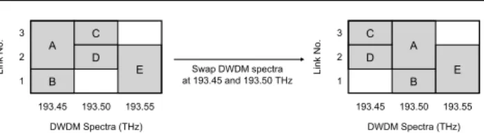
1 2 3 193.45 193.50 193.55 Li nk No . DWDM Spectra (THz) A B C D E 1 2 3 193.45 193.50 193.55 Li nk No . DWDM Spectra (THz) A B C D E Swap DWDM spectra at 193.45 and 193.50 THz
Fig. 5 Illustration of DWDM spectrum swapping process. A-E refer to transmitted signals, grey block are occupied link-spectral slots. Af-ter swapping the spectral continuity and collision free constraints are maintained. µ= { mini ( 0.1 ∆Pi ) for mini ( 0.1 ∆Pi ) <1 1 otherwise (18)
the launch powers,pwere then updated as
p:=p+µ∆p (19)
the iteration proceeds through equations (15) to (19) un-til the launch powers,p, converge. The algorithm was found to converge within 20 iterations for≈600 transmitters pro-vided the required SNR with margin can be achieved. The SNR margin was then increased incrementally until the iter-ation would no longer converge and no launch power solu-tion could be found. The maximum achievable margin was taken as the largest margin for which a solution to the power optimization was possible.
The DWDM channels as obtained from the routing mod-ulation and channel assignment ILP were then assigned to DWDM spectra. The separation of higher power signals has been shown[15] to reduce the overall interference. The as-signment was initial done manually to separate the lower channel numbers by assigning them well separated spectra. Since we are considering a fixed grid, each DWDM channel from the solution of Sect. 4.1, is self-contained, there is no spectral contiguity constraint. This allows all of the trans-mitters operating in a given DWDM channel to be moved to another spectra assignment without disturbing the spec-tral continuity or collision constraints. Thus we can swap all of the transmitters in one DWDM channel with another DWDM channel and this possibility was used to improve the DWDM channel spectral assignment. The process is il-lustrated in Fig. 5 for a simple network with three links and three DWDM channels. Thus the manual assignment was improved by swapping random pairs of DWDM chan-nels and calculating the achievable margin by following the iterative launch power optimization described above. The new DWDM spectra assignment was then retained if this improved the achievable margin or returned to the original spectral positions if it did not. Random pairs were swapped until no further improvement in achievable margin could be made.
For the NSF network utilizing a fixed PM-QPSK modu-lation format the initial grouped channel assignments from
0 50 100 150 200 250 300 Data Throughput Tb.s -1 DTAG 0 50 100 150 200 NSF 0 5 10 15 20 25 30 Google B4 Fixed modulation format, fixed power, worst case Adapted modulation format, optimized Power
Fig. 6 Total launch power across all transmitters in each DWDM chan-nel for the NSF network for the fixed PM-QPSK modulation solution. Initial grouped DWDM channel assignments, giving 2.6 dB SNR mar-gin. 0 1 2 3 4 5 1 10 20 30 40 50 60 70 80
Total Launch Power (mW)
DWDM Channel Number
Fig. 7 Total launch power across all transmitters in each DWDM chan-nel for the NSF network for the fixed PM-QPSK modulation solution. Optimal DWDM channel assignments, giving 3.3 dB SNR margin.
the ILP solution give an achievable SNR margin of 2.6 dB. Fig. 6 shows the total launch power, summed over all trans-mitters, in each DWDM channel after the individual launch powers have been optimized as described above but retain-ing the grouped channel assignments. Followretain-ing spectral assignment the achievable SNR margin was increased to 3.3 dB and Fig. 7 shows the total launch power, summed over all transmitters, in each DWDM channel, clearly show-ing that high power channels have been spectrally separated.
5 Results from Example Networks
For each of the three example networks, we consider an initial baseline optimization for a fixed modulation format, fixed launch power and assumed full channel occupancy. The fixed modulation format was chosen as the highest or-der modulation format that can be transmitted error free
be-tween the furthest spaced nodes. The SNR margin of this fixed modulation format solution was improved by opti-mizing the spectral assignment and individual launch pow-ers and showed that by moving away from the fixed power full occupancy assumption a considerable SNR margin was available for improving the network throughput. The net-works were then solved for adaptive modulation formats and finally with reduced initial SNR requirements.
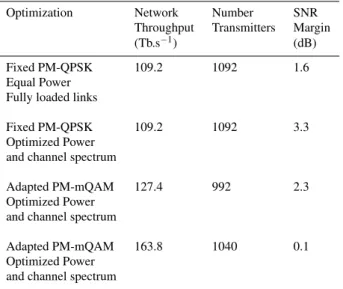
Beginning with the NSF network[33] of Fig. 1, under the assumption of equal launch power and fully loaded links the SNR of the longest shortest-path route allows PM-QPSK modulation. Thus PM-QPSK is the baseline traditional case for this network as it is suitable for transmission between all node pairs. By optimizing the routing and channel alloca-tion using the ILP described in Sect. 4.1 while maintaining the fixed PM-QPSK modulation format a network through-put of 109.2 Tb.s−1was achieved utilizing 1092 transmitters and with a worst case SNR margin of 1.6 dB. Taking this fixed PM-QPSK routing solution and optimizing the launch power and spectral allocation, as described in Sect. 4.2, a SNR margin of 3.3 dB was possible.
It is then the aim to utilize this margin to increase the net-work throughput. First the modulation format was adapted to the route by allowing the ILP of Sect. 4.1 the choice of all modulation formats on each route that have a required SNR less than the route worst case SNR calculated based on equal launch powers and fully loaded links. The adaptation of the modulation format increased the network throughput to 127.4 Tb.s−1 utilizing 992 transmitters. Following opti-mization of the launch power and spectral allocation a SNR margin of 2.3 dB was achieved. To further access this mar-gin the modulation formats required SNR were temporar-ily reduced by 1.6 dB during the initial routing, modulation and channel assignment. This allowed a network throughput of 163.8 Tb.s−1 utilizing 1040 transmitters and following launch power and spectral allocation achieved a SNR mar-gin of 0.1 dB.
Thus by optimizing the routing, modulation, launch power and spectral assignment the throughput has been in-creased by 50%, for the NSF network, over the baseline tra-ditional route independent case. Thus the network through-put has been increased by increasing the overall spectral ef-ficiency at the expense of the SNR margin. These results are summarized in Table 3.
Considering the much longer Google B4 network[34] of Fig. 2 under the assumption of equal launch power and fully loaded links it is not possible to transmit the lowest order modulation format, PM-BPSK across the longest shortest-path route. In order to achieve a SNR suitable for PM-BPSK on the longest shortest route under the assumption of equal launch power and fully loaded links the channel spacing was increased to 200 GHz and the number of channels reduced to 20. By optimizing the routing and channel allocation a
base-Table 3 Summary of results for the NSF network.
Optimization Network Number SNR
Throughput Transmitters Margin
(Tb.s−1) (dB)
Fixed PM-QPSK 109.2 1092 1.6
Equal Power Fully loaded links
Fixed PM-QPSK 109.2 1092 3.3
Optimized Power and channel spectrum
Adapted PM-mQAM 127.4 992 2.3
Optimized Power and channel spectrum
Adapted PM-mQAM 163.8 1040 0.1
Optimized Power and channel spectrum
line network throughput of 6.6 Tb.s−1was achieved utilizing 132 transmitters with a worst case SNR margin of 0.2 dB. Taking this fixed PM-BPSK routing solution and optimizing the launch power and spectral assignment a SNR margin of 3.3 dB was possible.
The limited number of channels leads to just one bi-directional connection between each node pair providing just 50 Gb.s−1, in each direction, between each node pair. Given that not all the channels will be occupied and that occupied channels can be separated in the launch power and spectral assignment process the channel spacing was re-duced to 100 GHz to provide 40 channels to improve the granularity of the routing solution. In order to connect the furthest spaced nodes the modulation formats required SNR were temporarily reduced by 1.3 dB during the initial rout-ing, modulation and channel assignment to allow PM-BPSK over the longest shortest-path route under the fully loaded links worst case. A network throughput of 13.2 Tb.s−1 utiliz-ing 264 transmitters was achieved and followutiliz-ing optimizutiliz-ing of the launch power and spectral assignment a SNR margin of 1.7 dB was possible.
To further improve the network throughput the modu-lation format was adapted to the route by allowing the ILP of Sect. 4.1 the choice of all modulation formats on each route that have a required SNR, that is temporarily reduced by 1.3 dB, less than the route worst case SNR calculated based on equal launch powers and fully loaded links. This allowed a network throughput of 26.4 Tb.s−1utilizing 300 transmitters and following launch power and spectral assign-ment optimization a margin just above 0.0 dB was achieved. Thus by optimizing the routing, modulation, spectral assignment and launch power the throughput has been in-creased by 300%, for the Google B4 network, over the base-line traditional route independent case. The reason for these
Table 4 Summary of results for the Google B4 network.
Optimization Network Number SNR
Throughput Transmitters Margin
(Tb.s−1) (dB)
Fixed PM-BPSK 6.6 132 0.2
200 GHz grid Equal Power Fully loaded links
Fixed PM-BPSK 6.6 132 3.3
200 GHz grid Optimized Power and channel spectrum
Fixed PM-BPSK 13.2 264 1.7
100 GHz grid Optimized Power and channel spectrum
Adapted PM-mQAM 26.4 300 0.0
100 GHz grid Optimized Power and channel spectrum
gains are twofold, firstly the increase in spectral efficiency at the expense of SNR margin and secondly the unblocking achieved by the reduction of granularity by allowing an in-creased number of channels. These results are summarized in Table 4.
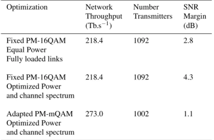
Finally we consider the shorter DTAG/T-Systems Na-tional core network[35] of Fig. 3, under the assumption of equal launch power and fully loaded links the SNR of the longest shortest-path route allows PM-16QAM modulation. Thus PM-16QAM is the baseline traditional case for this network as it is suitable for transmission between all node pairs. By optimizing the routing and channel allocation us-ing the ILP described in Sect. 4.1 while maintainus-ing the fixed PM-16QAM modulation format a network through-put of 218.4 Tb.s−1 was achieved utilizing 1092 transmit-ters and with a worst case SNR margin of 2.8 dB. Tak-ing this fixed PM-16QAM routTak-ing solution and optimizTak-ing the launch power and spectral allocation, as described in Sect. 4.2, a SNR margin of 4.3 dB was possible.
Allowing the ILP of Sect. 4.1 the choice of all modu-lation formats on each route that have a required SNR less than the route SNR calculated based on equal launch powers and fully loaded links was too complex in this case due to the larger number of formats given the higher overall SNR for this shorter network. In order to reduce the complexity the lower order formats, PM-BPSK and PM-QPSK were re-moved from the choice as these should not be used given the constraint to minimize the number of transmitters. The adaptation of the modulation format increased the network throughput to 273.0 Tb.s−1utilizing 1002 transmitters. Fol-lowing optimization of the launch power and spectral
allo-Table 5 Summary of results for the DTAG/T-Systems National core network.
Optimization Network Number SNR
Throughput Transmitters Margin
(Tb.s−1) (dB)
Fixed PM-16QAM 218.4 1092 2.8
Equal Power Fully loaded links
Fixed PM-16QAM 218.4 1092 4.3
Optimized Power and channel spectrum
Adapted PM-mQAM 273.0 1002 1.1
Optimized Power and channel spectrum
0 50 100 150 200 250 300 Data Throughput Tb.s -1 DTAG 0 50 100 150 200 NSF 0 5 10 15 20 25 30 Google B4 Fixed modulation format, fixed power, worst case Adapted modulation format, optimized Power
Fig. 8 Comparison of network throughput for the baseline fixed mod-ulation fixed power worst case fully loaded links case and the adapted modulation adapted power case. For the three network topologies tested.
cation a SNR margin of 1.1 dB was achieved. This margin could not be used to further increase the network through-put. The granularity of the network solutions is such that the next higher throughput solution has a SNR margin less than 0.0 dB and did not allow error free transmission.
Thus by optimizing the routing, modulation, spectral assignment and launch power the throughput has been in-creased by 25%, for the DTAG/T-Systems Nation core net-work, over the baseline traditional route independent case. These results are summarized in Table 5.
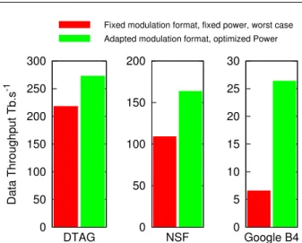
Fig. 8 summarizes the network throughput for each of the three test topologies for the baseline and optimized case. We have shown that for each of these three net-work topologies, with quite different diameters, the opti-mization of the launch power and channel spectra assign-ment leads to a SNR margin of around 3-4 dB for the fixed go anywhere baseline modulation format. This mar-gin can be traded to increase the average modulation for-mat order by approxifor-mately 1 b.s−1.Hz−1.pol−1increasing
the network throughput. For the smallest diameter DTAG/T-Systems National core network where the fixed modula-tion format is PM-16QAM, 4 b.s−1.Hz−1.pol−1, the in-crease should give a 25% improvement in throughput. For the NSF network where the fixed modulation format is PM-QPSK, 2 b.s−1.Hz−1.pol−1, the increase should give a 50% improvement in network throughput and finally for the Google B4 network where the fixed modulation format is PM-BPSK, 1 b.s−1.Hz−1.pol−1, the increase should give a 100% improvement in network throughput. This is approxi-mately what was observed except in the Google B4 network where an increase in throughput of 300% was achieved. It is believed the additional increase in network throughput is caused by unblocking in this network where the integer granularity on the number of transmitters can be a signifi-cant constraint to throughput. Initially with just 20 channels the topological bottleneck allows just one transmitter to op-erate between each node pair. By increasing the number of channels to 40 with a fixed PM-BPSK modulation format, 2 transmitters can operate between each node pair although the topological bottleneck would allow 2.5. The adaptation of the modulation format allows fewer transmitters to pro-vide the capacity over the short connections and releases bandwidth for the long connections, this allows the average number of transmitters between each node pair to approach 2.5 providing fuller utilization of the available bandwidth. This is similar to the higher gains observed for unblocking in flexible networks[42].
6 Conclusions
We have presented an algorithm to maximize the network throughput through static optimization of routing, modu-lation format, spectral assignment and launch power allo-cation within a nonlinear impaired optical mesh network. From a baseline case defined for fixed launch power, fully loaded channels with a fixed modulation format, suitable for the longest shortest-path route, the gains in network throughput for three example mesh networks have been quantified. For the DTAG, NSF and Google B4 network topologies an improvement of 25%, 50% and 300% in net-work throughput respectively was achieved.
We show that the SNR margin can be increased through the optimization of channel spectral assignment and launch power and that the SNR margin can be traded for network capacity by adapting the modulation format to the route. The increase in network throughput can be attributed to two ef-fects, the overall increase in spectral efficiency achieved as a result of the trade off against SNR margin and through an unblocking of network bottlenecks by utilizing less band-width for the shorter connections releasing bandband-width for the longer connections. The second effect is more
signif-icant in networks where there are few transmitter-receiver pairs connecting each node pair.
The optimization of routing, modulation format, spectral assignment and launch power allocation described here is a multistage process, first to optimize the routing, modulation format and channel assignment and then to maximize the SNR margin by optimizing the channel spectral assignment and launch power. Where sufficient SNR margin is avail-able the initial stage can be repeated to increase network throughput. This multistage process results in good but po-tentially sub-optimal results. An important avenue for future study would be to combine these stages to provide a single optimization process. In future work, it is also intended to include the benefits of improved spectral efficiency through the use of a flexible grid.
References
1. R.M. Schmogrow, D. Hillerkuss, M. Dreschmann, M. Huebner, M. Winter, J. Meyer, B. Nebendahl, C. Koos, J. Becker, W. Freude, J. Leuthold: Real-Time Software-Defined Multiformat Transmit-ter Generating 64QAM at 28 GBd. IEEE Photonics Technology Letters22(21), 1601 (2010). DOI 10.1109/LPT.2010.2073698 2. H.Y. Choi, T. Tsuritani, I. Morita: BER-adaptive flexible-format
transmitter for elastic optical networks. Optics Express20(17), 18652 (2012). DOI 10.1364/OE.20.018652
3. K. Roberts, C. Laperle: Flexible Transceivers. in 38th Eu-ropean Conference and Exposition on Optical Communica-tions, 1, p. We.3.A.3 (Amsterdam (NL), 2012) (2012). DOI 10.1364/ECEOC.2012.We.3.A.3
4. D.J. Ives, P. Bayvel, S.J. Savory: Physical Layer Transmitter and Routing Optimization to Maximize the Traffic Throughput of a Nonlinear Optical Mesh Network. inInternational Conference on Optical Network Design and Modeling, pp. 168–173 (Stockholm (SE), 2014) (2014)
5. A. Nag, M. Tornatore, B. Mukherjee: Optical Network De-sign With Mixed Line Rates and Multiple Modulation Formats. Journal of Lightwave Technology 28(4), 466 (2010). DOI 10.1109/JLT.2009.2034396
6. M. Jinno, H. Takara, B. Kozicki, Y. Tsukishima, Y. Sone, S. Matsuoka: Spectrum-efficient and scalable elastic optical path network: architecture, benefits, and enabling technologies. IEEE Communications Magazine 47(11), 66 (2009). DOI 10.1109/MCOM.2009.5307468
7. O. Gerstel, M. Jinno, A. Lord, S.J.B. Yoo: Elastic optical network-ing: a new dawn for the optical layer? IEEE Communications Magazine50(2), s12 (2012). DOI 10.1109/MCOM.2012.6146481 8. B. Kozicki, H. Takara, Y. Sone, A. Watanabe, M. Jinno: Distance-Adaptive Spectrum Allocation in Elastic Optical Path Network ( SLICE ) with Bit per Symbol Adjustment. inOptical Fiber Com-munication Conference, p. OMU3 (San Diego, CA. (USA), 2010) (2010)
9. K. Christodoulopoulos, I. Tomkos, E.A. Varvarigos: Elastic Band-width Allocation in Flexible OFDM-Based Optical Networks. Journal of Lightwave Technology29(9), 1354 (2011). DOI 10.1109/JLT.2011.2125777
10. E. Palkopoulou, M. Angelou, D. Klonidis, K. Christodoulopoulos, A. Klekamp, F. Buchali, E. Varvarigos, I. Tomkos: Quantifying Spectrum, Cost, and Energy Efficiency in Fixed-Grid and Flex-Grid Networks [Invited]. Journal of Optical Communications and Networking4(11), B42 (2012). DOI 10.1364/JOCN.4.000B42
11. F. Forghieri, R. Tkach, A. Chraplyvy, D. Marcuse: Reduction of four-wave mixing crosstalk in WDM systems using unequally spaced channels. IEEE Photonics Technology Letters6(6), 754 (1994). DOI 10.1109/68.300184
12. A. Adhya, D. Datta: Design methodology for WDM backbone net-works using FWM-aware heuristic algorithm. Optical Switching and Networking6(1), 10 (2009). DOI 10.1016/j.osn.2008.05.006 13. A. Nag, M. Tornatore, B. Mukherjee: Power Management in Mixed Line Rate Optical Networks. inIntegrated Photonics Re-search, Silicon and Nanophotonics and Photonics in Switching, 2, p. PTuB4 (OSA, Monterey, CA. (USA), 2010) (2010). DOI 10.1364/PS.2010.PTuB4
14. H. Beyranvand, J.a. Salehi: A Quality-of-Transmission Aware Dy-namic Routing and Spectrum Assignment Scheme for Future Elas-tic OpElas-tical Networks. Journal of Lightwave Technology31(18), 3043 (2013). DOI 10.1109/JLT.2013.2278572
15. D.J. Ives, S.J. Savory: Transmitter Optimized Optical Net-works. in National Fiber Optic Engineers Conference, p. JW2A.64 (OSA, Anaheim, CA. (USA), 2013) (2013). DOI 10.1364/NFOEC.2013.JW2A.64
16. D. Rafique, A.D. Ellis: Nonlinear Penalties in Dynamic Op-tical Networks Employing Autonomous Transponders. IEEE Photonics Technology Letters 23(17), 1213 (2011). DOI 10.1109/LPT.2011.2158603
17. A. Splett, C. Kurtske, K. Petermann: Ultimate transmission capac-ity of amplified optical fiber communication systems taking into account fiber nonlinearities. inEuropean Conference on Optical Communications, p. MoC2.4 (Montreux (CH), 1993) (1993) 18. P.P. Mitra, J.B. Stark: Nonlinear limits to the information capacity
of optical fibre communications. Nature411(6841), 1027 (2001). DOI 10.1038/35082518
19. A. Carena, G. Bosco, V. Curri, P. Poggiolini, M.T. Taiba, F. Forghieri: Statistical characterization of PM-QPSK signals after propagation in uncompensated fiber links. in 36th Eu-ropean Conference and Exhibition on Optical Communica-tion, 1, p. P4.07 (IEEE, Torino (IT), 2010) (2010). DOI 10.1109/ECOC.2010.5621509
20. F. Vacondio, O. Rival, C. Simonneau, E. Grellier, A. Bononi, L. Lorcy, J.C. Antona, S. Bigo: On nonlinear distortions of highly dispersive optical coherent systems. Optics Express20(2), 1022 (2012). DOI 10.1364/OE.20.001022
21. R. Dar, M. Feder, A. Mecozzi, M. Shtaif: Properties of nonlinear noise in long, dispersion-uncompensated fiber links. Optics Ex-press21(22), 25685 (2013). DOI 10.1364/OE.21.025685 22. R. Dar, M. Feder, A. Mecozzi, M. Shtaif: Accumulation of
non-linear interference noise in fiber-optic systems. Optics Express
22(12), 14199 (2014). DOI 10.1364/OE.22.014199
23. A. Carena, G. Bosco, V. Curri, Y. Jiang, P. Poggiolini, F. Forghieri: EGN model of non-linear fiber propagation. Optics Express
22(13), 16335 (2014). DOI 10.1364/OE.22.016335
24. H. Kogelnik, A. Yariv: Considerations of noise and schemes for its reduction in laser amplifiers. Proceedings of the IEEE52(2), 165 (1964). DOI 10.1109/PROC.1964.2805
25. A. Yariv: Signal-to-noise considerations in fiber links with peri-odic or distributed optical amplification. Optics Letters15(19), 1064 (1990). DOI 10.1364/OL.15.001064
26. P. Poggiolini, G. Bosco, A. Carena, V. Curri, Y. Jiang, F. Forghieri: The GN-Model of Fiber Non-Linear Propagation and its Applica-tions. Journal of Lightwave Technology32(4), 694 (2014). DOI 10.1109/JLT.2013.2295208
27. D.J. Ives, P. Bayvel, S.J. Savory: Adapting Transmitter Power and Modulation Format to Improve Optical Network Performance Utilizing the Gaussian Noise Model of Nonlinear Impairments. Journal of Lightwave Technology 32(21), 3485 (2014). DOI 10.1109/JLT.2014.2346582
28. P. Poggiolini: The GN Model of Non-Linear Propagation in Uncompensated Coherent Optical Systems. Journal
of Lightwave Technology 30(24), 3857 (2012). DOI 10.1109/JLT.2012.2217729
29. A. Carena, G. Bosco: Impact of the transmitted signal initial dis-persion transient on the accuracy of the GN-model of non-linear propagation. inEuropean Conference and Exposition on Optical Communications, 1, p. Th.1.D.4 (London (UK), 2013) (2013) 30. E. Ip, J.M. Kahn: Compensation of Dispersion and Nonlinear
Im-pairments Using Digital Backpropagation. Journal of Lightwave Technology26(20), 3416 (2008). DOI 10.1109/JLT.2008.927791 31. ETSI. Network Aspects (NA); Availability performance of path
elements of international digital paths (1998)
32. J.P. Snyder, Map Projections - A Working Manual. Tech. rep., U.S. Geological Survey Proffesional Paper 1395, Washington, D.C. (1987)
33. R. Ramaswami, K. Sivarajan: Design of logical topologies for wavelength-routed all-optical networks. inProceedings of IN-FOCOM’95, p. 10c.4.1 (IEEE Comput. Soc. Press, Boston, MA (USA), 1995) (1995). DOI 10.1109/INFCOM.1995.516012 34. S. Jain, A. Kumar, S. Mandal, J. Ong, L. Poutievski, A. Singh,
S. Venkata, J. Wanderer, J. Zhou, M. Zhu, J. Zolla, U. H¨olzle, S. Stuart, A. Vahdat: B4 : Experience with a Globally-Deployed Software Defined WAN. inSIGCOMM(2013) (2013)
35. D. Monoyios, K. Vlachos: Multiobjective Genetic Algorithms for Solving the Impairment-Aware Routing and Wavelength Assign-ment Problem. Journal of Optical Communications and Network-ing3(1), 40 (2011). DOI 10.1364/JOCN.3.000040
36. K. Cho, D. Yoon: On the general BER expression of one-and two-dimensional amplitude modulations. IEEE Trans-actions on Communications 50(7), 1074 (2002). DOI 10.1109/TCOMM.2002.800818
37. P.K. Vitthaladevuni, M.S. Alouini, J. Kieffer: Exact BER com-putation for cross QAM constellations. IEEE Transactions on Wireless Communications 4(6), 3039 (2005). DOI 10.1109/TWC.2005.857997
38. P. Poggiolini, G. Bosco, A. Carena, R. Cigliutti, V. Curri, F. Forghieri, R. Pastorelli, S. Piciaccia: The LOGON Strat-egy for Low-Complexity Control Plane Implementation in New-Generation Flexible Networks. inOptical Fiber Communication Conference, 1, p. OW1H.3 (Anaheim, CA (USA), 2013) (2013). DOI 10.1364/OFC.2013.OW1H.3
39. D. Banerjee, B. Mukherjee: A practical approach for routing and wavelength assignment in large wavelength-routed optical net-works. IEEE Journal on Selected Areas in Communications14(5), 903 (1996). DOI 10.1109/49.510913
40. N. Wauters, P. Demeester: Design of the optical path layer in multiwavelength cross-connected networks. IEEE Journal on Selected Areas in Communications 14(5), 881 (1996). DOI 10.1109/49.510911
41. J.Y. Yen: Finding the K Shortest Loopless Paths in a Network. Management Science17(11), 712 (1971). DOI 10.2307/2629312 42. P. Wright, A. Lord, S. Nicholas: Comparison of Optical
Spec-trum Utilization Between Flexgrid and Fixed Grid on a Real Net-work Topology. in Optical Fiber Communication Conference, p. OTh3B.5 (Los Angeles, CA. (USA), 2012) (2012). DOI 10.1364/OFC.2012.OTh3B.5