Clemson University
TigerPrints
All Theses
Theses
12-2018
Steroid OpenFlow Service Scalability Analysis
Khayam Anjam
Clemson University, [email protected]
Follow this and additional works at:
https://tigerprints.clemson.edu/all_theses
This Thesis is brought to you for free and open access by the Theses at TigerPrints. It has been accepted for inclusion in All Theses by an authorized administrator of TigerPrints. For more information, please [email protected].
Recommended Citation
Anjam, Khayam, "Steroid OpenFlow Service Scalability Analysis" (2018).All Theses. 2965.
S
TEROID
O
PENFLOW
S
ERVICE
S
CALABILITY
A
NALYSIS
A Thesis
Presented to
the Graduate School of
Clemson University
In Partial Fulfillment
of the Requirements for the Degree
Master of Science
Computer Engineering
by
Khayam Anjam
December 2018
Accepted by:
Dr. Kuang-Ching Wang, Committee Chair
Dr. Harlan Russell
Abstract
Modern cloud applications are hosted on data centers across vast geographical scopes and ex-change large amounts of data continuously. Transmission Control Protocol (TCP) is the most popular protocol for reliable data transfer; however, due to TCP’s congestion control mechanism, maximum achievable throughput across a large bandwidth-delay product (BDP) network is limited. Various solutions exist to enhance data transfer throughput but they usually require non-trivial and explicit installation and tuning of specialized software on both sides which makes deployment limited. A software defined networking (SDN) based solution "Steroid OpenFlow Service (SOS)" was developed that utilizes multiple parallel TCP connections to transparently enhance network performance across a large BDP network. OpenFlow is used to transparently redirect user traffic to nearby service machines called SOS agent and these agents use multiple TCP connections to transfer data fast across large BDP network. While SOS has shown significant improvements in data trans-fer throughput, there are multiple factors which affect its performance. This study focuses on SOS scalability analysis targeting four critical factors: CPU utilization of SOS agents, sockets used for parallel TCP connections, how OpenFlow is used and network configurations. Through this study, the SOS agent code was revamped for performance improvements. Experiments were conducted on the National Science Foundation’s CloudLab platform to assess the effect of the above-mentioned factors on SOS performance. Results have shown improvement in throughput per SOS session from 10.96Gbps to 12.82Gbps by removing CPU bottleneck on 25Gbps network. SOS deployment over an InfiniBand network has shown a linear increase in throughput to 23.22Gbps with optimal net-work configurations. Using OpenFlow to support multiple client connections to the same server have increased throughput from 12.17Gbps to 17.20Gbps. The study showed that with code-level improvements and optimal network configurations, SOS performance can be improved substantially.
Dedication
I dedicate this thesis to my parents, siblings, and friends for their love, motivation, and support during my studies.
Acknowledgments
I would like to thank my advisor, Dr. Kuang-Ching Wang, for all the help, support, and guidance throughout my studies. Dr. Wang was very helpful and provided valuable feedback and direction towards my research. I am honored to have had multiple opportunities to present demos and talks at conferences/workshops. I would also like to thank Dr. Russell and Dr. Ligon for their help and guidance for study and research. Dr. Russell’s coursework helped me to understand various networking concepts in greater depth. I also really appreciate Dr. Ligon, his coursework helped me to better understand modern computer architecture and parallel programming concepts which helped me a lot during my master’s research. Finally, I would like to thank my colleagues Ryan, Geddings, Qing, Junaid, Caleb, and Casey for their help during my research and experimentation. I would also like to thank CloudLab support team Kirk Webb and Will Robinson for their help and support towards my experiments.
Contents
Title Page . . . i
Abstract . . . ii
Dedication . . . iii
Acknowledgments . . . iv
List of Tables . . . vii
List of Figures . . . viii
1 Introduction 1 1.1 Steroid OpenFlow Service . . . 1
1.2 Problem and Objectives . . . 2
2 Background 4 2.1 SOS Architecture . . . 4
2.1.1 Agent . . . 4
2.1.2 OpenFlow Controller . . . 7
2.2 High Speed Interconnects . . . 8
3 SOS Scalability 10 3.1 Compute Resources . . . 10
3.1.1 Effect on SOS Performance . . . 10
3.1.2 Experimental Studies . . . 11
3.1.2.1 Experimental Setup . . . 11
3.1.2.2 Results and Analysis . . . 13
3.2 Sockets . . . 14
3.2.1 Effect on SOS Performance . . . 14
3.2.1.2 Traffic Shaping with Netty Sockets . . . 15
3.2.1.3 Buffers . . . 16
3.2.2 Experimental Studies . . . 16
3.2.2.1 Experimental Setup . . . 16
3.2.2.2 Results and Analysis . . . 17
3.3 OpenFlow . . . 20
3.3.1 Multiple Client Connections . . . 20
3.3.2 Experimental Studies . . . 23
3.3.2.1 Experimental Setup . . . 24
3.3.2.2 Results and Analysis . . . 25
3.4 Network Configurations . . . 26
3.4.1 Experimental Setup . . . 26
3.4.1.1 TCP Tuning . . . 29
3.4.1.2 Maximum Transmission Unit . . . 30
3.4.2 Results and Analysis . . . 31
3.5 Summary of the Observations . . . 34
4 Conclusion and Future Work 35 4.1 Conclusion . . . 35
4.2 Future Work . . . 36
Appendices 40
A Equipment Problems 40
List of Tables
3.1.1 Agent with code-level concurrency . . . 13
3.1.2 Previous SOS agent implementation . . . 13
3.2.1 HashMap get method look-up time (ms) . . . 16
3.2.2 Performance with non-blocking IO . . . 17
3.2.3 Performance with blocking IO . . . 18
3.3.1 OpenFlow rules to redirect traffic from the client to the SOS agent and vice versa . 22 3.3.2 OpenFlow rules to forward traffic between SOS agents . . . 23
3.3.3 OpenFlow rules to redirect traffic from agent to server and vice versa . . . 23
3.3.4 Performance with multiple client connections . . . 25
List of Figures
1.1.1 SOS deployment the in the cloud . . . 2
2.1.1 SOS agent architecture . . . 6
3.1.1 SOS agent class diagram . . . 11
3.1.2 SOS deployment over 25Gbps Ethernet link with 50m latency . . . 12
3.2.1 Blocking vs non-blocking socket architecture . . . 14
3.2.2 Blocking vs non-blocking socket throughput . . . 18
3.2.3 Blocking vs non-blocking sender CPU utilization . . . 19
3.2.4 Blocking vs non-blocking receiver CPU utilization . . . 20
3.3.1 Logical flows in an SOS deployment . . . 22
3.3.2 Experiment topology for multiple client connections . . . 24
3.4.1 SOS deployment model in the cloud . . . 27
3.4.2 Experimental setup for multiple SOS agents . . . 27
3.4.3 CloudLab experiment topology . . . 28
3.4.4 Multiple agent experimental setup . . . 31
3.4.5 Multiple agent SOS performance . . . 32
Chapter 1
Introduction
1.1
Steroid OpenFlow Service
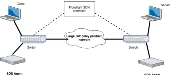
To transfer data as quickly as possible requires a network capable of facilitating high throughput data transfer. Transmission Control Protocol (TCP) can be used between endpoints to transfer data rapidly and reliably. However, latency poses a problem over wide area networks. TCP cannot fully utilize the available bandwidth due to its congestion control mechanism. Solutions exist to increase throughput by using techniques like parallel TCP. To achieve increased throughput, modifications to end-user machines are required. Modification required by the end-user entails the installation of additional softwares and fine-tuning these softwares to support the transport protocols. This is oftentimes difficult for average network users who either do not have permission, software, or expertise to perform such modifications.
Steroid OpenFlow Service (SOS) leverages SDN to intercept and manipulate the traffic within the network.
Figure 1.1.1: SOS deployment the in the cloud
1.2
Problem and Objectives
SOS has shown significant improvement in throughput for memory to memory and disk to disk transfers. However, these improvements are limited by the factors such as SOS agent’s architecture, how OpenFlow is used and network configuration such as MTU, TCP buffer sizes, etc.
For example, previously SOS agent was coded to use a single CPU core for each SOS session[17]. For each running SOS session, the CPU is 1) continuously polling over all the open sockets (each agent have at least one open socket to end-host and multiple sockets to another agent) 2) For each incoming packet it appends a sequence number and 3) if agent is receiving traffic from another agent it needs to write each packet into a buffer and deliver received packets in sequence to end host. Section 3.1 talks about compute resources and its effect on the SOS performance.
SOS agents used blocking sockets so for each open socket, there is a separate thread running. So if N parallel TCP connections are open then there are N+1 threads running (N for each socket and 1 for socket server). Comparing this to blocking IO where read and write buffers are utilized so each socket can read/write in parallel. Section 3.2 describes a Netty based non-blocking socket implementation.
Section 2.1.2 focuses on OpenFlow, SDN Controller architecture, and how they are used to handle an SOS connection. SOS controller uses client IP address, destination IP address and destination port to identify an SOS connection. If a particular client IP wants to start multiple connections to the same server IP and port number, SOS cannot recognize the second SOS connection. Multiple client
connections are desirable to achieve better performance if the client to agent link has high bandwidth and high latency. Section 3.3 describes a multiple client connection use case using OpenFlow and its effect on SOS performance.
Section 3.4 discusses an InfininBand based network and describe how to setup and test SOS. We also studied the effect of network configurations such as MTU and TCP buffer size, on SOS performance.
Chapter 2
Background
2.1
SOS Architecture
Steroid OpenFlow Service (SOS) consists of three main components: SOS agent, SDN controller and SDN switches.
A Software defined network handles packet redirection through the installation of OpenFlow rules on SDN switches. the SDN controller orchestrates this process and communicates with switches. It also manages an on-going SOS session. Compute servers are used to run SOS agents which carry out per packet operations. Due to the widespread adoption and use of the OpenFlow protocol, SOS has been designed using OpenFlow as the enabling SDN technology; however, the architecture can be adapted to use any SDN protocol with equivalent features.
2.1.1
Agent
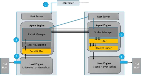
Figure 2.1.1 shows SOS agent’s architecture. An agent is divided into three components: a rest server, an agent engine, and a host engine.
Rest Server
The rest server is the agent interface to communicate with the SDN controller and other agents. The rest server 1) receives incoming SOS connection requests from the controller and acts on it, 2) talks to other agents and exchanges vital information like ports. Older agent implementation used UDP packets to send controller requests to agents. UDP does not make any promise on reliable
delivery. Moreover, once an agent receives a UDP packet, it doesn’t have any mechanism to respond back to the controller if the agent runs into an issue and is unable to entertain controller request. For example, if the agent is already running on its maximum capacity then the agent should be able to give feedback to the controller. With the rest server, the controller will send an HTTP POST request to the agent with information about incoming SOS connection. That agent can check its resources that whether it is capable of serving. Once an agent has made its decision, it will respond back to the controller about its decision.
The Rest server also solved the problem of port selection between agents. Previously agents used a hard-coded list of ports, the agent crashed if any of the ports were in use by other processes. SOS agents used to assign a range of ports for each client, e.g 11000-11036 for the first client, 11037-11072 for the second client. This is changed to a more dynamic and flexible approach in this thesis. Sockets can choose any ports numbers, once the port selection is done, the agent will send the port information to the other agent as a rest call.
request=RequestTemplate{ isClientAgent=false,
transferID='68041fac-6bc1-41a7-9625-aee8f4ffcf1f', clientIP='10.0.0.111', clientPort=42858, serverAgentIP='10.0.0.12', clientAgentIP='10.0.0.11', numParallelSockets=30, bufferSize=1000, queueCapacity=4000, serverIP='10.0.0.211', serverPort=5001 }, ports=[ 51718, 51720, 51722, 51724, 51726, 51728, 51730,
51732, 51734, 51736, 51738, 51740, 51742, 51744,
51746, 51748, 51750, 51752, 51754, 51756, 51758,
51760, 51762, 51764, 51766, 51768, 51770, 51772,
51774, 51776 ]
The Rest API also makes it easy to deploy and manage an agent in a cloud environment and to provide developer logging.
Host engine
The host engine interacts with end-hosts (client/ server) and the agent engine. Upon receiving the traffic from the client, the host engine appends a sequence number and forward it to the agent engine. The host engine also interacts with the agent engine’s receive buffer to check for incoming data and forwards it to the end-host.
Figure 2.1.1: SOS agent architecture
Agent engine
The agent engine interacts with the host engine to receives packets. It then forwards it to the remote agent using one of its parallel TCP connections. Similarly, the agent engine on the remote
side receives the incoming traffic and puts them in the buffer. Netty a non-blocking IO socket library is used as It is efficient for high throughput applications. Details about Netty and the sockets are discussed in Section 3.2.
2.1.2
OpenFlow Controller
For SOS to achieve end-user transparency, the network architecture must be conducive to the trans-parency implemented by the SDN. OpenFlow switches need to be strategically deployed to achieve transparency. One requirement is the presence of at least one OpenFlow switch at each side of a data transfer path, one in the path nearby the client and another close to the server.
Figure 1.1.1 shows the basic SOS deployment with two switches. This example deployment consists of two OpenFlow switches, one SOS agent connected to each switch, and a client and server machine connecting to switches. When the client-server connection is initiated, SOS is automatically invoked to improve data throughput.
SOS can be deployed across more complex network typologies where it might not be feasible to have the client and the server directly connected to the SDN switches but the SOS just requires SDN switches to be somewhere on a path between end-hosts. Ideally, the switch should be geographically closer to the end-host to ensure the single TCP connection is not affected by latency.
OpenFlow is used to seamlessly intercept and manipulate the TCP connection between the end hosts. This interception is done when the TCP handshake begins and is terminated when the TCP connection is closed or upon a timeout in the case of an ungraceful close. On the client side of the network, the OpenFlow switch redirects and rewrites the TCP packets from the client to the client side SOS agent and back from the client side SOS agent to the client. The client’s SOS agent serves as the transparent proxy for the remote server and to relay any data sent from the client-agent to the remote SOS agent nearby the server. The server’s SOS agent will receive data from the client’s SOS agent. The server’s OpenFlow switch performs both TCP packet redirection and rewrites from the server’s SOS agent to the server and from the server to the server’s SOS agent. Due to the packet rewrite employed by the flows installed in the OpenFlow switches, the server thinks it is communicating directly with the client and the client thinks it is communicating directly with the server.
The specific flows installed in the OpenFlow switches will vary depending on the network topol-ogy; however, they must consist of layer 2, layer 3 and layer 4 packet header matches and rewrites in
order to achieve transparency. The SOS OpenFlow controller can determine the network topology and install the appropriate flows automatically.
The controller can also handle the normal or non-SOS traffic and lets the traffic to go through the network without any redirection and rewrites. Configuring the controller with SOS modules and SOS connection is also part of the network level configurations.
Details about how SDN controller handles an SOS connection are explained in 2.1.2.
2.2
High Speed Interconnects
High performance computing (HPC) applications need the lowest possible latency and higher band-width for best performance. For example, a 10Gbps Ethernet can have latency 5 to 6 time higher than InfiniBand [11]. InfiniBand is a communication standard in compute networking which is used for high performance computing. It offers high throughput and very low latency. In contrast to Peripheral Component Interconnect (PCI) which sends data in parallel, InfiniBand sends data in serial and is capable of carrying multiple channels at the same time as a multiplexed channel.
IP over InfiniBand (IPoIB) is a protocol that defines how IP packets are sent over InfiniBand. The InfiniBand driver creates a network interface which makes a host channel adapter act as a network interface card and we can assign an IP address to it. Because SOS is a network application which uses TCP parallel connections to enhance the throughput, it had to use InfiniBand in its IPoIB mode. Using InfiniBand in IPoIB mode instead of remote direct memory access (RDMA) adds extra overhead to CPU. IPoIB cannot use the host channel adapter (HCA) capabilities and network traffic goes through the operating system’s TCP/IP stack which means a system call is required for every incoming packet and the host CPU must handle all of the network IO read/ write operations. In section 3.4.1 InfiniBand operating modes and effect of MTU on its performance are discussed.
Remote direct memory access (RDMA) is a direct memory access from one machine into that of another machine without the involvement of the operating system [23]. As RDMA enables direct data transfer to or from application memory, it eliminates the need to copy data between application memory and the operating system data buffers. It means that no work is required by the CPU and operating system. In addition, when an application performs an RDMA operation, the data is delivered directly to the network which reduces the latency and enables fast message transfer.
Host Channel Adapter (HCI) is a network interconnect based on InfiniBand technology. It provides the specification for the transmission of data between processors and I/O devices. It also provides a port connection to other InfiniBand devices which can be connected to another HCA or an InfiniBand switch[24].
Chapter 3
SOS Scalability
Four aspects of the SOS agents are analyzed 1) compute resources, 2) how sockets are assigned for parallel TCP connections, 3) OpenFlow’s role and 4) network configurations.
3.1
Compute Resources
Modern computers and commercial servers are equipped with multi-cores which mean they are capable of running multiple programs in parallel. New SOS Agent architecture leverages concurrency and multi-core support which resulted in improved throughput.
3.1.1
Effect on SOS Performance
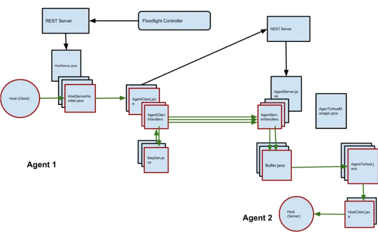
Previously SOS agent was programmed to run on single CPU core so It was not able to leverage the code-level concurrency for an ongoing SOS connection. This limitation was also identified in previous studies on SOS[8]. In that SOS agent, a pooling-based model was used where a thread loop over all the sockets to check for data. This model is changed to an event-driven programming and non-blocking socket implementation. Figure 3.1.1 shows the class diagram for an SOS agent. Red boxes show the current SOS session, a black arrow shows the flow of the control plane information(controller request and port information) and green arrow shows the flow of the data.
Upon receiving a controller request for an incoming SOS connection, the agent sets up all the sockets. The HostClient.java object receives incoming data from the end host using non-blocking sockets and forwards it to the AgentClient.java. Which appends the sequence number and
for-Figure 3.1.1: SOS agent class diagram
wards the traffic using AgentClientHandler.java. These handlers are used to connect to the remote agent. Each of these handlers has their own life cycle so Java Virtual Machine (JVM) can map them to single or multiple cores based on the application need and system load. On the receiving agent,AgentServer.java have multiple handler objects and these handles map to a Buffer.java ob-ject. Buffer.java object is used to buffer the data packets and Java HashMap is used to implement buffer storage. Details about the buffer implementation and its performance are explained in section 3.2.1.3.
3.1.2
Experimental Studies
3.1.2.1 Experimental Setup
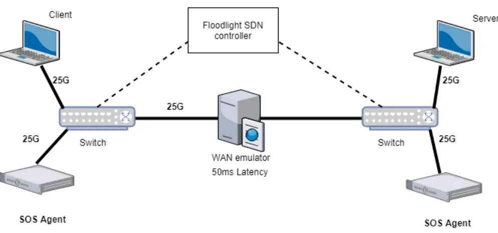
Experiments conducted on CloudLab Utah with new SOS agent implementation showed better results. A test was run with 2 client processes connecting to 2 server processes over a 25Gbps
Figure 3.1.2: SOS deployment over 25Gbps Ethernet link with 50m latency
Ethernet link with 50ms latency. A server is used to simulate the wide area network due to CloudLab issues explained in Appendix A.
Hardware Specification
CPU model name : Intel(R) Xeon(R) CPU E5-2640 v4 @ 2.40GHz (20 Cores) Memory: 65GB NIC: Ethernet controller: Mellanox Technologies MT27710 Family [ConnectX-4 Lx] (25G Ethernet Adapter)
Wide Area Network Node setup
The WAN node emulates latency using Linux TC tools
sudo tc qdisc add dev ib0 root netem limit buffer_size delay 25 ms
buffer_size represents buffer size for TC queue. Ideally, this value should be more than 50% of the max packet rate * delay. Specifying a small Buffer size can lead to queue dropping the packets [5].
BW = 25 Gbps Delay = 50 ms
Buffer Size >= 50% of 149.01 MB Compute Nodes setup
On Compute nodes we need to route traffic through the WAN node. It is done by setting the WAN node as a gateway for all the compute nodes.
sudo route add -net 10.0.0.0/24 gw 10.0.0.100 CPU Tuning
By default, Linux uses the ’powersaver’ CPU governor mode. We set it in performance mode on all compute and the WAN node.
cpufreq - set -r -g performance
3.1.2.2 Results and Analysis
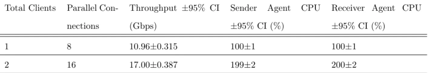
The table below shows the results with the 95% confidence interval (CI). Total Clients Parallel
Con-nections
Throughput ±95% CI (Gbps)
Sender Agent CPU ±95% CI (%)
Receiver Agent CPU ±95% CI (%)
1 12 12.82±0.312 315±44 333±53
2 20 17.10±0.421 390±47 401±48
Table 3.1.1: Agent with code-level concurrency Total Clients Parallel
Con-nections
Throughput ±95% CI (Gbps)
Sender Agent CPU ±95% CI (%)
Receiver Agent CPU ±95% CI (%)
1 8 10.96±0.315 100±1 100±1
2 16 17.00±0.387 199±2 200±2
Table 3.1.2: Previous SOS agent implementation
Comparing the first two rows of the tables 3.1.1 and 3.1.2 shows that new SOS agent implemen-tation achieved better performance by removing single CPU core bottleneck. With the new agent, client achieved throughput of 12.82Gbps where old agent achieved 10.96Gbps. Comparing the CPU usage from both experiments shows that the new agent has better CPU utilization. It shows that if experiments are run over 40Gbps or 100Gbps network where the client is sending at a higher data rate and more parallel connections are required to fill the pipe, the old agent will become a bottleneck. Because it has to do more processing on a single CPU core so the new agent will be able to scale much better because it can use as many resources as needed so it can achieve better performance in large bandwidth networks.
3.2
Sockets
Sockets are an important component of SOS agents. New SOS agent implementation uses Netty for socket implementation. Netty, a non-blocking buffer based sockets library, is designed for high performance applications where high throughput and lower delays are vital. Netty also scales better under heavy loads as it reduces resource consumption by minimizing unnecessary memory copy operations [10].
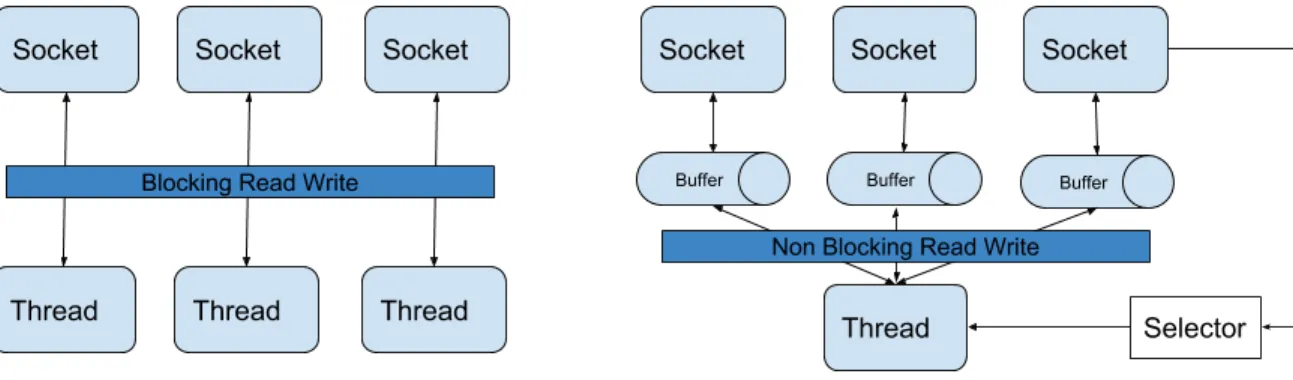
Figure 3.2.1: Blocking vs non-blocking socket architecture
3.2.1
Effect on SOS Performance
Figure 3.2.1 shows the difference between blocking IO and non-blocking IO (NIO). NIO uses a single thread to handle the socket selector and dispatch all read, write operations. So thread handler is just dispatching the operation which means a large number of operations can be carried out fast and efficiently.
The blocking IO uses a separate thread to handle each socket connection and another thread for the listening socket. So the number of threads is directly proportional to the number of socket connections open. Blocking IO will perform better if less number of socket connections are open because they have a dedicated thread to handle the data operations. However, if a large number of clients connect there will be a large number of parallel TCP connection open. For example, if there are 5 SOS sessions running and each session have 32 parallel TCP connections so a total of 5 * 32 = 160 sockets are open. A quad chip CPU with 6 core per chip machine have 4 * 6 = 24 processing nodes to handle 161 threads. Instantiating and running all these threads need CPU and memory resources and even with the thread pooling the CPU context switching will still be taking
place which is an extra overhead on the processor.
3.2.1.1 Netty Socket Library
Modern computers have multiple cores so modern applications employ complex multi-threading tech-niques to effectively use system resources. Basic thread pooling pattern in Netty is as: 1) The thread is selected from pool’s free thread list and assigned to run a submitted task (An implementation of Runnable), 2) When the task is complete, the Thread is returned to the pool and becomes available for reuse.
Netty’s EventlLoop employs two fundamental APIs: Concurrency and networking. The package io.netty.util.concurrent provides the thread executor. The classes in the package io.netty.channel extend these in order to interface with Channel events. In this model, an EventLoop is powered by one thread that never changes and all the runnable tasks can be summited directly to the EventLoop for execution. Depending upon the configuration and the available cores, multiple Event Loops can be created to optimize the resource usage. Events triggered by the IO flow through the ChannelPipeline which have one or more ChannelHandlers installed. In Netty, all IO operations and events are handled by the thread that has been assigned to the EventLoop. One socket receives some data in the buffer, it transverses the pipeline from bottom to top. As Netty is a buffer based NIO socket implementation which means instead of a process/ thread waiting for the data to be received so the application has access to the buffer all the time.
3.2.1.2 Traffic Shaping with Netty Sockets
SOS can push traffic across a large bandwidth-delay product network fast and efficiently by utilizing parallel TCP connections, however sometimes achieved throughput is not equal to the incoming data rate from the client. This led to the agent socket buffer getting full and evenly dropping the incoming traffic. To avoid this we need to adjust the data reception rate based upon how fast we can forward this traffic across the BDP network. This has been implemented in SOS agents using Netty’s traffic handlers. Data read rate from the client can be adjusted based on the feedback from the remote agent. Remote agent periodically sends information to the other agent using the rest call. Based on this information, the agent adjusts the maximum read rate from the client. The agent also periodically removes the sending rate limit for the short amount to time because sometimes network conditions changes and an agent is capable of sending at the higher rate.
Another future prospect is how we send data over the multiple parallel channels. Under a multi-path deployment where some channels can be faster than the other and some can have lower latency than the other. For such type of deployments, SOS agent has defined a flexible structure which provides a baseline to setup different traffic sending strategies which can be implemented in future [16].
3.2.1.3 Buffers
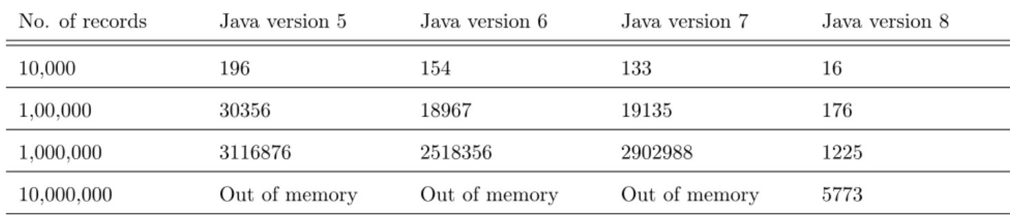
Buffers are an important component of SOS agents. Data received over the parallel TCP channels is often out of order and needed to store temporary and sorted before it can be forwarded. The structure needed to implement buffers is required to be efficient because agents send/ receive traffic at the high data rate. Java 1.8 HashMap is used to implement buffers as it has very optimal look-up time[4]. Table 3.2.1 shows the get method look-up in milliseconds.
No. of records Java version 5 Java version 6 Java version 7 Java version 8
10,000 196 154 133 16
1,00,000 30356 18967 19135 176
1,000,000 3116876 2518356 2902988 1225
10,000,000 Out of memory Out of memory Out of memory 5773
Table 3.2.1: HashMap get method look-up time (ms)
3.2.2
Experimental Studies
3.2.2.1 Experimental Setup
The experiment ran on CloudLab Utah setup 3.1.2. Two client processes were started simultane-ously to test memory to memory transfer over 50ms latency network. All the nodes have following specifications
Hardware Specification
CPU model name : Intel(R) Xeon(R) CPU E5-2640 v4 @ 2.40GHz (20 Cores) Memory: 65GB NIC: Ethernet controller: Mellanox Technologies MT27710 Family [ConnectX-4 Lx] (25G Ethernet Adapter)
The WAN node emulates latency using Linux TC tools
sudo tc qdisc add dev ib0 root netem limit buffer_size delay 25 ms
buffer_size represents buffer size for TC queue. Ideally, this value should be more than 50% of the max packet rate * delay. Specifying a small Buffer size can lead to queue dropping the packets [5].
BW = 25 Gbps Delay = 50 ms
Buffer Size >= 50% of 149.01 MB Compute Nodes setup
On Compute nodes we need to route traffic through the WAN node. It is done by setting the WAN node as a gateway for all the compute nodes.
sudo route add -net 10.0.0.0/24 gw 10.0.0.100 CPU Tuning
By default, Linux uses the ’powersaver’ CPU governor mode. It needed to be set in performance mode on all compute and the WAN node.
cpufreq - set -r -g performance
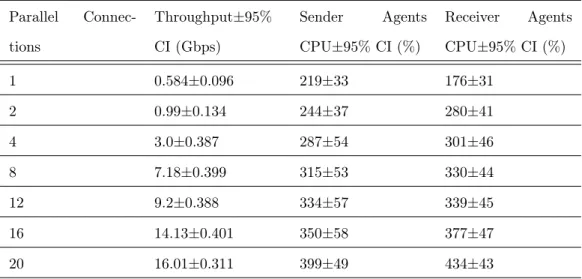
3.2.2.2 Results and Analysis
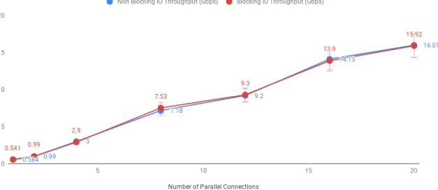
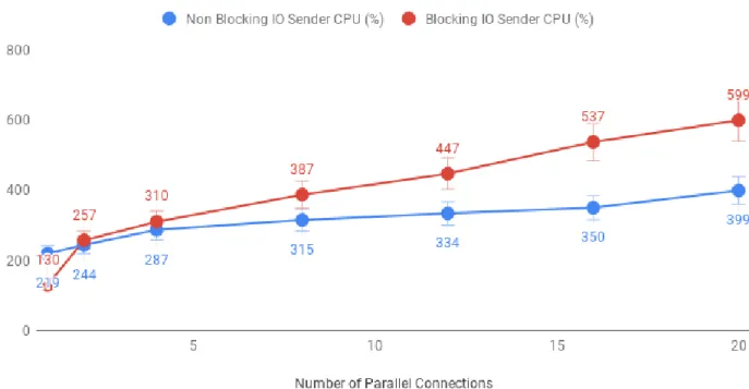
Parallel Connec-tions Throughput±95% CI (Gbps) Sender Agents CPU±95% CI (%) Receiver Agents CPU±95% CI (%) 1 0.584±0.096 219±33 176±31 2 0.99±0.134 244±37 280±41 4 3.0±0.387 287±54 301±46 8 7.18±0.399 315±53 330±44 12 9.2±0.388 334±57 339±45 16 14.13±0.401 350±58 377±47 20 16.01±0.311 399±49 434±43
Figure 3.2.2: Blocking vs non-blocking socket throughput Parallel Connec-tions Throughput±95% CI (Gbps) Sender Agents % CPU±95% CI Receiver Agents % CPU±95% CI 1 0.541±0.091 130±22 132±19 2 0.99±0.1 257±46 253±43 4 2.9±0.345 310±46 % 440±46 8 7.53±0.424 387±39 853±49 12 9.3±0.432 447±46 1233±52 16 13.9±0.42 537±49 1681±54 20 15.92±0.245 599±46 1997±13
Table 3.2.3: Performance with blocking IO
By comparing the table 3.2.3 and 3.2.2, it can be seen that non-blocking and blocking sockets have almost the same throughput. However, a larger difference can be seen in the CPU utilization for both where non-blocking socket’s CPU utilization is much lesser and almost uniform than the blocking IO sockets. Table 3.2.3 shows that CPU utilization of receiving agent which keep increasing with the increased number of sockets. For blocking sockets, there is a separate thread for each socket waiting for data. For example, when 20 sockets are open, on the receiving agent there are 20 different threads waiting for incoming data. Although data might not be always available these threads will
Figure 3.2.3: Blocking vs non-blocking sender CPU utilization
always be running. That’s why CPU utilization for the agent with blocking sockets keep increasing linearly with the increased number of open sockets. Results didn’t show any significant improvement in throughput with non-blocking sockets due to a large number of CPU cores available on each agent node in the experimental setup. Each of the agent-server has 20 cores so with 20 or fewer sockets open, the operating system can easily map them to a separate core. There is also no background workload or network traffic on these agent machines that’s why blocking sockets have achieved the same performance even with a large number of open sockets. However, if the experiment is conducted on higher bandwidth infrastructure i.e 40Gbps or 100Gbps where a large number of socket connections are needed to fill the pipe, blocking sockets can become a performance limiting factor as date rate being higher, more number of parallel sockets are required to fully utilize the bandwidth.
Figure 3.2.4: Blocking vs non-blocking receiver CPU utilization
3.3
OpenFlow
Software Defined Networking is used to achieve data transfer transparency by the control over the flow of end-to-end data transfer. This allows SOS to improve data transfer throughput without end-user intervention. Moreover, SOS also ensures that only the traffic of interest is manipulated without causing any harm to other data transfers and background traffic in the network.
For SOS to achieve end-user transparency, network architecture must be conducive to the trans-parency implemented by the SDN.
3.3.1
Multiple Client Connections
The controller uses a global white-list configuration file with information about the SOS connection. This file also contains information like data chunk size, number of parallel TCP connections. A white-list entry contains server IP, client IP, the server TCP port number, and the longevity of the entry as expressed by a start time and a stop time [18]. Below code snippet adds an SOS connection by specifying client IP address, server IP address and server port number.
-X POST -d '{" server -ip - address ":" 10.0.0.211 ",
" server -tcp - port ":" 5001 ", " client -ip - address ":" 10.0.0.111 "}'
Another SOS connection can be white-listed by entering its information in the file. Current controller’s implementation can’t differentiate if two clients are trying to connect two the same server port. For example, a client iperf process tries to initiate two parallel connections to the same server port i.e 5001.
iperf -c 10.0.0.211 -t 100 -i 1 -P 2
A user might want to open multiple sessions at the same time because latency between the client and the client-agent is considerable, client to agent-client link is high bandwidth and multiple parallel connections are needed to fill the pipe. As a controller cannot differentiate between two separate connections so It cannot install OpenFlow flow rules properly which will result in underutilization of available bandwidth. Changes were made in floodlight source-code so it can differentiate between SOS sessions and install flows properly.
Table 3.3.1, 3.3.2, 3.3.3 shows the flow entries for an SOS session. Changes were made into installed flows to make SOS recognize the second TCP connection originating from the same client to the same server port. Above changes resulted in significant improvement in single SOS session throughput which is explained below.
SOS Connection Handling
SOS is designed to support a variety of network configurations, typologies and software/ hardware switches. Figure 3.3.1 shows the logical flows in an SOS deployment. In this example scenario, SOS will transparently redirect client A traffic to SOS agent X which will forward it over a long link to SOS agent Y and eventually will redirect it to server B. Tables below shows the numbered flows for the SOS connection manipulation. SOS controller can install flows on the client-side interception switch to match and intercept the packets from the client which were meant for the server. OpenFlow flow rules redirect intercepted packets to the nearby SOS agent. The destination MAC and IP addresses and the destination TCP port of the intercepted packets are rewritten by the OpenFlow rule on the switch to the agent MAC, IP, and open TCP port. All TCP packets destined for the client from the agent TCP port such as TCP ACKs, will be addressed by the agent machine’s network stack to the client’s TCP port, IP address, and MAC address; however, to maintain transparency, the same interception OpenFlow switch on the client-side of the network rewrites the source MAC,
Figure 3.3.1: Logical flows in an SOS deployment
IP, and TCP port to the server’s MAC and IP addresses and TCP port. This bi-directional packet interception, rewrite, and redirection allows a TCP connection to be established from the client to the local SOS agent where the client believes it has actually connected to the server across the network.
Flow
No. Flow Match Flow Action Results
1 in_port=portA ipsrc=ipA tcpsrc=tcpA macdst=macX ipdst=ipX tcpdst=tcpX output=portX
TCP packets from A to B Now appear to be from A to X 2 in_port=portX ipdst=ipA tcpdst=tcpA macsrc=macB ipsrc=ipB tcpsrc=tcpB output=portA
TCP packets from X to A Now appear to be from B to A
Table 3.3.1: OpenFlow rules to redirect traffic from the client to the SOS agent and vice versa Now, because SOS provides a transparent service, any data relayed to the client-side SOS agent over the TCP connection must eventually make it to the real destination (the server) which knows the data semantics and can interact with the client appropriately over TCP. To accomplish this, the client-side SOS agent reliably relays any data to the server-side SOS agent.
The server-side SOS agent establishes a TCP connection with the server. All TCP packets from the server-side SOS agent are addressed to the server machine’s MAC, IP, and TCP port but contain server-side SOS agent source headers. The interception OpenFlow switch on the server-side of the network contains a flow installed by the SOS OpenFlow controller to match these packets and rewrite
Flow
No. Flow Match Flow Action Results
3 in_port=portX
ipsrc=ipX ipdst=ipY
output=portY TCP packets from X to Y are relayed unmodified from X to Y
4 in_port=portY
ipsrc=ipY ipdst=ipX
output=portX TCP packets from Y to X are relayed unmodified from Y to X
5 in_port=portX
ipsrc=ipX ipdst=ipY
output=portY TCP packets from X to Y are relayed unmodified from X to Y
6 in_port=portY
ipsrc=ipY ipdst=ipX
output=portX TCP packets from Y to X are relayed unmodified from Y to X
Table 3.3.2: OpenFlow rules to forward traffic between SOS agents
the source MAC and IP addresses and TCP port to those of the client machine. When these packets arrive at the server, the server will think they have originated from the client. Any TCP packets from the server to the client are intercepted by a similar flow in this same interception OpenFlow switch, their destination MAC address, IP address, and TCP port will be rewritten to those of the server-side SOS agent, and they will be redirected to the server-side SOS agent.
Flow
No. Flow Match Flow Action Results
7 in_port=portY ipdst=ipB tcpdst=tcpB macsrc=macA ipsrc=ipA tcpsrc=tcpA output=portB
TCP packets from Y to B Now appear to be from A to B 8 in_port=portB ipsrc=ipB tcpsrc=tcpB macdst=macY ipdst=ipY tcpdst=tcpY output=portY
TCP packets from B to A Now appear to be from B to Y
Table 3.3.3: OpenFlow rules to redirect traffic from agent to server and vice versa
Tables above shows the OpenFlow rules to manipulate an SOS connection. The same set of rules are used to setup multiple SOS sessions.
3.3.2
Experimental Studies
The experiment conducted on CloudLab Utah (25G Ethernet 50ms link) showed the following results. Average latency between the client and the client-Side SOS agent is 1.139 ms. The experiment is run in two different styles, 1) Client initiates a single connection to the server, 2) Client initiates
two connections to the server. Both tests were ran using iperf, for the first test -P 1 flag was passed which means just use a single stream, for the second test -P 2 flag was passed which means client want to start two simultaneous streams.
Figure 3.3.2: Experiment topology for multiple client connections
3.3.2.1 Experimental Setup Hardware Specification
CPU model name : Intel(R) Xeon(R) CPU E5-2640 v4 @ 2.40GHz (20 Cores) Memory: 65GB
NIC: Ethernet controller: Mellanox Technologies MT27710 Family [ConnectX-4 Lx] (25G Eth-ernet Adapter)
Wide Area Network Node setup
The WAN node emulates latency using Linux TC tools
sudo tc qdisc add dev ib0 root netem limit buffer_size delay 25 ms
buffer_size represents buffer size for TC queue. Ideally, this value should be more than 50% of the max packet rate * delay. Specifying a small Buffer size queue dropping the packets [5].
BW = 25 Gbps Delay = 50 ms
Buffer Size >= 50% of 149.01 MB
On Compute nodes we need to route traffic through the WAN node. It is done by setting the WAN node as a gateway for all the compute nodes.
CPU Tuning
By default, Linux uses the ’powersaver’ CPU governor mode. It needed to be set in performance mode on all compute and the WAN node.
cpufreq - set -r -g performance
3.3.2.2 Results and Analysis
The table below shows the results achieved with the 95% confidence interval (CI). Client Streams Throughput ±95% CI (Gbps)
1 12.17±0.521
2 17.20±0.420
Table 3.3.4: Performance with multiple client connections
Table 3.3.4 shows that two client streams to a server achieved better throughput than the single stream. Previously, without multiple client connection support, SOS wasn’t able to recognize the second client connection which limited the throughput. On large networks i.e 40G, 100G, multiple client streams are required to fully utilize the network. This is also true if the latency between the client and the client-facing agent is high. For example, on the current experimental setup at-least, 2 client connections are required to fully utilize the available bandwidth. On higher bandwidth net-works more parallel connections will be needed to fill the pipe. This concludes that the multiple client connection support can make significant throughput improvement and throughput improvement be more visible on higher bandwidth networks i.e. 100Gbps.
3.4
Network Configurations
The final part of the SOS scalability analysis was to study how SOS behaves under various network configurations i.e MTU size, TCP buffer size, and the number of parallel TCP connections. Impact of MTU and TCP buffer size are discussed below in section 3.4.1 and 3.4.1.
3.4.1
Experimental Setup
Figure 3.4.2 shows the experimental setup to test the SOS on CloudLab platform. Previous SOS studies on CloudLab, spanned over two sites having compute resources at the Clemson University and the University of Utah. The connection between Clemson and Utah utilizes AL2S setup which can provide 100 gigabit Ethernet between both sites. However, due to recent issues in CloudLab platform (explained in Appendix A) forced to use custom topology which uses APT Utah site only. setup has two types of networks 1) InfiniBand to simulate WAN 2) Ethernet for end-host to the agent communication. Setting up InfiniBand is also different than the traditional Ethernet-based network. As SOS is a TCP application so traditional InfiniBand network didn’t work out of the box. An additional IP over IB layer is required to run a TCP application. InfiniBand’s specifications are discussed in section 3.4.1.
A dedicated node serves as Wide Area Network simulator. Each of the agent nodes uses the WAN node as a gateway and forward all the traffic through it. The WAN node than adds simulated latency using Linux TC [7] before forwarding traffic to remote agents. Floodlight is used as SDN controller which connects to the switches. setup has one physical OpenFlow switch and each SOS agent node also runs OVS virtual switch [19].
The topology shown in Figure 3.4.3 represents the nodes at APT Utah site. Total 21 nodes are used in the experiment with 10 at each site. 10 nodes are used as the end hosts (clients and servers) and 10 are agents. All the agents connect through InfiniBand with traffic tunneled through the WAN node. Each client/server connects through a 10G Ethernet network. Details about the resources used in the experiment are discussed in the following sections.
Hardware Specifications
The nodes specification at APT Utah site are as follow:
Agents, Clients, Servers
Figure 3.4.1: SOS deployment model in the cloud Figure 3.4.2: Experimental setup for multiple SOS agents • RAM: 16GB Memory
• Disks: Four 500GB 7.2K SATA Drives - 1.36 TB RAID0 partition for data transfers • NIC: 10GbE Dual port embedded NIC (Broadcom)
• NIC: 56GbE Mellanox Technologies MT27500 Family ConnectX-3
Network Connectivity
Data network is connected with physical OpenFlow enabled HPE Moonshot-45XGc Switches. An OpenFlow instance was created in the experimental setup and configured with the SDN controller IP address and port. Switches send the packet-ins to the controller using this OpenFlow link and controller configures the switch by pushing flows of rewrites and redirection. The SOS agents also run a virtual switch for packet rewrites and in the experiment Open vSwitch was used in each agent which is a virtual switch. These switches were also connected to the same controller running on a separate CloudLab node. Each agent and the WAN node have Mellanox Technologies MT27500 Family ConnectX-3 56G InfiniBand network interface card with stock Mellanox drivers installed. Tests using native verb API shown a maximum possible of 43Gbps. iperf was used to test maximum possible throughput with IP over IB which was 27Gbps.
Figure 3.4.3: CloudLab experiment topology
Wide Area Network Node
The WAN node emulates latency using Linux TC tools
sudo tc qdisc add dev ib0 root netem limit buffer_size delay 25 ms
buffer_size represents buffer size for TC queue. Ideally, this value should be more than 50% of the max packet rate * delay. Specifying a small Buffer size queue dropping the packets [5].
InfiniBand BW = 56 Gbps
Max achieved with IP over IB = 27 Gbps Delay = 50 ms
buffer_size >= 50% of 160.93 MB
However, the max possible throughput with IP over IB is around 27 Gbps so we can specify a smaller buffer size value.
Compute Nodes
On Compute nodes, we need to redirect traffic over InfiniBand network from Ethernet. It is been done using iptables. 10.0.0.XX specifies an Ethernet network IP address whereas 172.0.0.XX is related InfiniBand network IP address.
sudo iptables -t nat -A OUTPUT -p tcp -d 10.0.0. XX -j DNAT -{}- to 172.0.0. XX sudo iptables -t nat -nvL
We also need to use the WAN node as a gateway for all the compute nodes so traffic can be redirected through it. 172.0.0.100 is the IP address of the WAN node.
sudo route add -net 172.0.0.0/24 gw 172.0.0.100 CPU Tuning
By default, Linux uses the ’powersaver’ CPU governor mode. We set it in performance mode on all compute and the WAN node.
cpufreq - set -r -g performance Interrupt binding
To fully utilize network interface card on a NUMA machine, We can assign a dedicated CPU core to handle all the IO interrupts. Mellanox provided NIC drivers have a performance tuning tool with can be used for interrupt binding. I used HIGH_THROUGHPUT profile. This profile offers optimized interrupt handling: Interrupts are handled by cores closest to the device and there is no overlap in core assignment between different interfaces.
sudo mlnx_tune -p HIGH_THROUGHPUT
3.4.1.1 TCP Tuning
TCP performance at the application layer can be increased by the use of multiple parallel streams and by tuning TCP buffer size. Using multiple parallel streams generally gives better results than an optimized buffer size with a single stream [6]. Parallel streams can recover from failures quicker and are more presumably to steal bandwidth from the other streams. SOS agent uses multiple TCP connections in parallel to achieve higher throughput over large bandwidth-delay product links. This section discusses how this is accomplished and how the amount of throughput improvement can be tuned. The default maximum TCP window size of the Linux kernel is 64KB which means that at most 64KB can be sent on the link without an acknowledgment. Modern, large BDP links are capable of buffering far more than this. For example, a 10Gbps link between two geographical locations with approximately 50ms round-trip latency so this link can buffer 10Gbps x 0.050s or around 60MB of data which is far more than the maximum allowable TCP window size. SOS agent Linux kernels are configured with TCP window scaling enabled; however, achieving and sustaining
full window in practice is difficult due to TCP congestion control algorithms and network packet loss. The use of multiple TCP connections in parallel in conjunction with TCP window scaling between the SOS agents provides each TCP connection with the potential to achieve an average window size greater than the kernel defaults.
Although parallel streams give better performance over single stream TCP with tuned TCP buffers, default maximum Linux TCP buffer sizes are still too small for networks with large band-width i.e 40G or higher [15]. On the agents and the WAN node, h-TCP [9] was used as a congestion control algorithm which is designed for high speed and long distance networks. Following TCP tuning parameters were used based on recommendations [21].
net . core . rmem_max = 134217728
net . ipv4 . tcp_rmem = 4096 87380 67108864
The first line specifies that testing with receive buffers up to 128MB is allowed. In the second line, first value 4096 means the minimum receive buffer size for each TCP connection and this buffer is always allocated to a TCP socket even system is under heavy network load. 87380 specifies the default receive buffer allocated for each TCP socket. 67108864 specifies the maximum receive buffer that can be allocated for a TCP socket [21].
net . core . wmem_max = 134217728
net . ipv4 . tcp_wmem = 4096 65536 67108864
The first line specifies that testing with send buffers up to 128MB is allowed. In the second line, first value 4096 means the minimum receive buffer size for each TCP connection and this buffer is always allocated to a TCP socket even system is under heavy network load. 65536 specifies the default receive buffer allocated for each TCP socket. 67108864 specifies the maximum receive buffer that can be allocated for a TCP socket [21].
net . ipv4 . tcp_congestion_control = htcp net . ipv4 . tcp_mtu_probing =1
HTCP is the recommended congestion control for the high performance applications and mtu probing is recommended for the hosts with jumbo framed enabled.
3.4.1.2 Maximum Transmission Unit
IP over InfiniBand works in two modes 1) datagram and 2) connected mode. In datagram mode, unreliable datagram transport is used for transmission so the NIC maximum transmission unit
Figure 3.4.4: Multiple agent experimental setup (MTU) can be calculated as
IPoIB MTU = L2 MTU - IPoIB encapsulation header
For example, normally InfiniBand fabric in datagram mode have 2048 MTU so the IPoIB MTU will be
2048 - 4 = 2044 bytes.
In connected mode, reliable connected transport is used, in connected mode, transport allows an MTU up to the maximal IP packet size of 65K which reduces the number of packets needed for handling large TCP/ UDP packets and increases the performance for large messages [25][2]. Effect of MTU size on performance is discussed in section 3.4.1.
3.4.2
Results and Analysis
Table 3.4.1 shows with the increase in the number of SOS agents, throughput increased linearly to 21.45Gbps. After that, there is a slight improvement in throughput to 23.22Gbps. Throughput decreased with the addition of new SOS connections due to the increasing number of parallel streams. As the number of parallel connection increased the packet drop count also increased which resulted in TCP back-off for all the connections and overall throughput decreased. The increase in throughput
Parallel
Con-nections No. of AgentPairs Throughput±95%CI (Gbps) Sender CPU±95%CI ReceiverCPU±95% CI
25 1 08.69±0.452 264 ±45% 247±49%
50 2 15.25±0.51 507±47% 460±45%
75 3 21.45±0.421 605±48% 586±46%
80 4 23.22±0.59 687±47% 608±43%
85 5 22.21±0.541 703±51% 640±53%
Table 3.4.1: SOS performance with optimal network configurations
Figure 3.4.5: Multiple agent SOS performance
is limited by several factors. For this experiment, a server is used to emulate the WAN node with Linux traffic control (TC). TC [7] is a user-space program to emulate various network conditions such as latency, delays, and network losses etc. A user-space program doesn’t have direct access to hardware or memory and transition between the user and the kernel mode is expensive so for high performance applications such as SOS which send/receive data at a very high rate, it is a major bottleneck. Another performance limiting factor is using IPoB mode of InfiniBand. A traditional InfiniBand device can process packet headers which mean it saves CPU cycles and directly forwards the data to the interested application. However, in IPoIB mode, operating system’s TCP/IP stack will be processing the packets so expensive CPU cycles will be used for the processing.
Effect of MTU
Figure 3.4.6: SOS agents CPU utilization
were run in IPoIB’s default mode (Datagram, 2044 MTU) which meant that we have more number of IP packets to handle with overheads (headers). Smaller MTU also increases the IO interrupts and CPU usage because each packet has to pass through the kernel’s TCP/IP stack. For the high performance applications as SOS, these factors negatively affect the performance. Experiments ran with 2044 MTU showed a maximum throughput of 10Gbps which is half of the performance gained with 65520 MTU. By using larger MTU sizes and enabling jumbo frames improved network performance by making data transmissions more efficient.
3.5
Summary of the Observations
This study discussed the SOS performance and the scalability with focus on 1) resource utilization, 2) Sockets used for the parallel TCP connections, 3) OpenFlow role and 4) Network configurations. Section 3.1 discussed how leveraging code-level concurrency yielded in better CPU utilization and improved throughput. The thesis also discussed how this performance improvement will be more prominent if larger bandwidth networks i.e 40Gbps or 100Gbps are used. Section 3.2 compared blocking and the non-blocking IO and discussed their pros and cons. Blocking IO sockets perform better with lower load i.e less number of connections open at a time. However, it doesn’t scale well with the increased number of open connection due to a direct thread to socket mapping. This implies that NIO scales better under the heavy load and the higher bandwidth environment. The experiment conducted in section 3.2 showed the increase in the CPU utilization for the blocking sockets which eventually will become a bottleneck on high bandwidth networks where a large number of parallel TCP connections are required to fully utilize the bandwidth.
Section 2.1.2 talked about the OpenFlow role in SOS. Floodlight [12] SDN controller is used to handle the SOS connection and it transparently redirects traffic to/from the SOS agents. By adding the support for multiple client connections to the same server, SOS yielded in better throughput. This section also highlighted that how multiple client connection support will be more vital in the large bandwidth networks where the client to the client-facing agent latency is significant and network requires multiple streams to fill the pipe.
Table 3.4.1 showed the results collected by running the SOS over an InfiniBand based network with simulated latency. It showed that with the increase in the number of active SOS agents, throughput increased linearly to a limit and after that increase in throughput was limited. This limited increase in the throughput is due to the limitations in the experimental setup which were discussed in section 3.4.2.
This study also showed that SOS can be deployed in any cloud environment and the linear increase in throughput can be achieved. All four of the experiments have targeted different SOS parts and have shown overall improvements in the performance and showed how improvement in performance can be seen if the network with higher bandwidth is used to deploy SOS.
Chapter 4
Conclusion and Future Work
4.1
Conclusion
This thesis addressed the SOS scalability issues with the focus on four main factors, CPU utilization, sockets used for the parallel TCP connections, OpenFlow role and network configurations. The study showed that with the code-level improvements and the optimal network configurations, SOS performance improved substantially. For example, with non-blocking sockets, SOS can have a large number of open connections without putting too much strain on CPUs. With the support of multiple client connection, the client can have two or more parallel connections to the same server that will increase the throughput. The study also showed that how does SOS behave if it is deployed on an InfiniBand based network and how does MTU effects the performance. As a part of the study, SOS agent code was also revamped which solved the issues of agents crashing unexpectedly. Developing a REST interface for SOS agent made it easy to deploy it as a service in the cloud. It also made agent’s interaction with the SDN controller more seamless. With improved debug logging its also easier to debug issues, extend and add new features. SOS architecture can be easily deployed in different network topologies - both on-premise and cloud-based environments. Evolution in the CloudLab environment showed that SOS architecture can scale elastically and linearly in a data center networking environment with high capacity links. Combining SOS with existing data transfer technologies makes it a critical piece of a data transfer ecosystem and it can also provide a boost to unassisted data transfers.
4.2
Future Work
There are still some SOS scalability aspects that needed to be studied. For example, binding two or more network interface cards (NIC) together to increase the bandwidth. Modern operating system and switches support link aggression (LAG) where multiple NICs can be bound together, either in the active-backup mode for link redundancy or in the active-active mode to increase the bandwidth. SOS scalability is needed to be analyzed with a multi-NIC setup. NSF’s CloudLab platform have hardware with two NICs but on each machine, one NIC is used for the administrative management. Another important aspect to be studied is how a client can use multiple agents and split traffic between them. If the client is capable of sending data faster than the agent’s capability to handle it than multiple agents should be used to entertain a single client connection. This also means there is a need to devise a mechanism to split the client’s traffic. Research is also needed on OpenFlow controller that how OpenFlow can be used to split traffic between multiple SOS agents.
Bibliography
[1] CloudLab http://CloudLab.us
[2] InfiniBand https://www.kernel.org/doc/Documentation/InfiniBand/ipoib.txt [3] Mellanox Tuning Guide https://community.mellanox.com/docs/DOC-1523
[4] Java HashMap Performance https://www.opencodez.com/java/java8-map-performance-improvements.htm
[5] Traffic Control in Linux https://lists.Linuxfoundation.org/pipermail/netem/2007-March/001094.html
[6] Balancing TCP Buffer vs Parallel Streams in Application Level Throughput Optimization Esma Yildirim Louisiana State University, Baton Rouge, LA, USA Dengpan Yin Louisiana State Uni-versity, Baton Rouge, LA, USA Tevfik Kosar Louisiana State UniUni-versity, Baton Rouge, LA, USA
[7] Traffic Control https://Linux.die.net/man/8/tc
[8] R. Izard, J. Deng, Q. Wang, K. Xu, and K.-C. Wang, "An agent-based framework for production software defined networks," Int. J. Commun. Netw. Distrib. Syst., vol. 17, no. 3, pp. 254-274, Jan. 2016. [Online]. Available: https://doi.org/10.1504/IJCNDS.2016.080112
[9] A. Rajendran, P. Mhashilkar, H. Kim, D. Dykstra, G. Garzoglio, and I. Raicu, "Optimizing large data transfers over 100gbps wide area networks," in 2013 13th IEEE/ACM International Symposium on Cluster, Cloud, and Grid Computing, May 2013,
[11] InfiniBand and Ethernet http://www.hpcadvisorycouncil.com/pdf/IB_and_10GigE_in_HPC.pdf [12] Floodlight SDN Controller http://www.projectfloodlight.org/
[13] Dixit, Advait, et al. "Towards an elastic distributed SDN controller." ACM SIGCOMM com-puter communication review. Vol. 43. No. 4. ACM, 2013.
[14] Mano, M. Morris. Computer system architecture. Prentice-Hall of India, 2003.
[15] Tierney, Brian. "TCP tuning guide for distributed applications on wide area networks." Usenix & SAGE Login 26.1 (2001): 33-39.
[16] SOS Agent Code http://github.com/khayamgondal/SOSAgent [17] SOS Agent Code http://github.com/rizard/sos-agent
[18] Floodlight for SOS http://github.com/khayamgondal/SOSForFloodlight [19] Open vSwitch http://www.openvswitch.org
[20] GENI https://portal.geni.net/ [21] Fasterdata http://fasterdata.es.net/
[22] A Study of Hardware Assisted IP over InfiniBand and its Impact on Enterprise Data Center Performance Ryan E. Grant1, Pavan Balaji2 , Ahmad Afsahi1
[23] RDMA https://en.wikipedia.org/wiki/Remote_direct_memory_access [24] HCI https://www.webopedia.com/TERM/H/Host_Channel_Adapter.html
[25] INF MTU https://forum.open-e.com/showthread.php/1341-Neat-comparison-of-the-different-scsi-target-implementations?s=
Appendix A
Equipment Problems
Previously cross site CloudLab (Clemson-Utah) link was used to conduct experiments on SOS. Clemson-Utah link has 50ms latency which is ideal to test a Wide Area Network. SOS setup needs at-least one SDN switch to do forwarding between the end hosts and agents. During testing SOS on the CloudLab platform, various hardware and network issues were observed. Most common of them were
• A trunk port disappeared on a physical switch VLAN-delineated OpenFlow instance. • All frames of any size and L3/L4 type traverse Al2S link in one direction
• No cross-site connectivity (Ping not successful)
• No error or drop reports on any switch both OpenFlow and non-OpenFlow
Issues related to no cross-site connectivity happened due to buggy firmware in Dell switches. Each hardware platform has many firmware revisions that are released. However, an often overlooked purpose of firmware revisions is to provide a mechanism for the company to address bugs discovered in the field, in real-world customer deployments. One of such issues was due to a bug in Dell’s OpenFlow Switch running Force10 Firmware. Due to this issue cross site ping and any IP traffic forwarding was unsuccessful. A way around for this bug was to use particular OpenFlow instance (instance 2) on the Dell switches in topology. Same issue (no cross-site connectivity) reappeared during running experiments for the SOS scalability analysis but applying previous solutions (recreating VLANs, using OF instance 2) doesn’t seem to solve the problem this time.
Updating all the switches was also requested to the CloudLab support team, however, switches on CloudLab Utah were not updated due to administration issues. To further debug the issue TCP dumps from the controller and the end hosts were analyzed.
Tests were conducted using floodlight controller’s LLDP/BDDP packets which are used to dis-cover topology. The controller sends LLDP packet to a switch which is broadcasted to the other connected switches and they send it back to the controller; that’s how controller learns topology. Running tcpdump on controller’s control plan showed that the controller is not receiving LLDP responses back from the switches. It means that at-least one switch between the Clemson-Utah link is dropping packets. To further narrow down the issue, two separate typologies spanning a single site (Clemson and Utha) were created and checked for connectivity. Separate sites were working fine which means that there is an aggregation switch which is dropping the packets. To further debug the issue, information such as TCP dumps, flow rules from all the switches involved in Clemson-Utah topology was needed. Due to the shortage of time and lack for active communication from CloudLab support team forced to use the single site (Utah) and use simulated latency for WAN.
Appendix B
Agent Stability and Improvements
The SOS agents were not very stable and crashed after a few runs which required work towards improving the stability. Due to the unexpected crash of agents sometimes the TCP ports used by agent were not freed. Due to that after an agent crash restarting the agent was not enough, we needed to find the process and manually kill it using the pkill command to free the ports. New agent implementation removed these scenarios and implemented a proper application life cycle.
Developer logging is also improved in the new SOS agent implementation. It makes easy to find a bug, debug and resolve it. With the rest interface for the agent, its easier to deploy SOS as a service in the cloud and other services can interact with it over the rest api. Installing SOS agents doesn’t require any special preparation. Previously, SOS agent code needed to be compiled using a C compiler with additional dependencies i.e setting up file descriptors. New SOS agent is packed as a Java Jar binary which could be downloaded from GitHub and started as Java application by running following command.