Analysis of Self Excited Induction Generator for
Standalone Micro-Hydro Scheme
Dinesh Kumar Mallik
1, Jesif Ahmed
2 1Council for Technical Education and Vocational Training, Nepal2
School of Technology, Assam Don Bosco University
Abstract: Most of population which they do not have electricity are living in remote rural areas or off grid, to provide electricity for remote areas is a challenging task which require a huge investment and infrastructure, it is therefore convenient to provide them with decentralized energy system like distributed generation or hybrid system etc. utilizing the available renewable energy. This paper presents study results about the dynamic analysis of self-excited induction generator for micro-hydro power plant in which generation is carried out by the use of self-excited induction generator (SEIG). It can be a very effective solution to the power shortage in the hilly regions of developing countries, like Nepal, Bhutan etc. It is more economical than other possible electric power sources, because it requires simple design and semi-skilled persons; local manufacturers can manufacture the components. SEIG is becoming more and more popular, mainly due to its low cost, simple construction, robustness of its rotor design and low maintenance requirements. When Induction motor is used as a generator, the major problem is its terminal voltage fluctuation at varying load and varying speeds. To predict the dynamic behavior of SEIG driven by a constant torque from micro-hydro turbine is carried out by using MATLAB/SIMULINK under different loading conditions. The model has been developed using “SimPowerSystem” library from MATLAB to perform the simulation.
Keywords: Induction Generator, Induction Motor, SFIG, Electronic load controller, dump load, SVC, Hydro-turbine, MATLAB SIMULINK
1.
Introduction
The increasing concern toward environmental problems (global warming which is caused by emission of green house gases), the depletion of fossil fuel, the oil prices uncertainty, growing energy demand and the need for low generation cost has led to look for an alternatives and sustainable source of energy by harnessing abundance renewable energy which is available in the nature such as wind, solar, biogas, micro, mini, and small hydro, at this time the generation of electricity has been mainly dominated by conventional sources such as Thermal, Nuclear etc.to meet the growing demand for energy and also to electrify the remote areas where the extension of grid is not economical and unfeasible [1,2].
Wind and hydro systems requires electro-mechanical energy conversion system to convert the kinetic energy available in water as for hydro system or kinetic energy available in wind as for wind system to rotational mechanical energy through prime mover to drive the generator which is couple with the prime mover directly or indirectly through coupling arrangement to produce electricity [3].
Previously synchronous generator dominate the generation of electricity but induction generator emerge and become more applicable in the field of renewable energy because of their relative advantages over the synchronous generator, the induction generator is rugged can with stand rough condition, brushless, low cost, and low maintenance and operation cost, self-protected against short-circuit, and it is capable of generating power at various range of speed, it require external source for excitation to generate a rotating magnetic field, the required reactive power for excitation can be supplied from the grid in this mode known as grid connected induction generator, or it can be supplied by a capacitor connected to the stator terminal in this mode it is known as self-excited induction generator [2].
When an induction machine is driven by prime-mover (water turbine or wind turbine) to speed higher than synchronous speed in negative sleep the induction machine can operate as generator mode. When capacitors are connected across stator terminal it can operate in self-excited mode [4-8].
Minimum excitation capacitors required for excitation can be calculated by analytical method [9,10], Fuzzy Logic approach [11], nodal
admittance method, loop analysis method and L-C resonance method [12-14,15].
The major drawback of using self-excited induction generator (SEIG) in micro-hydro power plant is its terminal voltage and frequency fluctuation at varying loads and speed. Frequency can be controlled by using converter and inverter whereas terminal voltage can be controlled by adjusting the value of excitation capacitors connected in stator terminals of SEIG and its speed [16-19].
2. Working of Induction Generator
An induction generator or asynchronous generator is a type of alternating current (AC) electrical generator that uses the principles of induction motors to produce power. Mostly Induction generators are used to generate the power in small scale. Generally to reduce the installation cost of micro-hydro power plant or wind power plant Induction generator is used. The working principle of Induction Generator (IG) is same as that of induction Motor (IM). When three phase supply is fed to the IM, a RMF (Rotating Magnetic Field) is produced which rotates at the speed of synchronous speed(N
s=
120fP , Where ‘ Ns’ is synchronous speed in rpm, ‘f’ is frequency in Hz and ‘P’ is no. of poles). When RMF is passed over the static rotor, current is induced which cause rotor flux, the polarity of rotor flux is opposite to the RMF and hence rotor drags behind the RMF and rotates in the same direction as RMF rotates. The Induction motor normally turns slightly lesser than synchronous speed, hence sleep (s) is developed.
The difference between synchronous speed (Ns) and rotor speed (Nr) is so called slip and it is expressed in percentage (%).
% 𝑆𝑙𝑖𝑝(𝑆) =𝑁𝑠 −𝑁𝑟
𝑁𝑠 × 100 --- (1)
If rotor is rotated at more than synchronous speed (Ns) by using prime- mover (water turbine) the slip will become –ve and the rotor current is generated in the opposite direction. This generated rotor current produces the RMF in the rotor which push back on to the stator field. This causes a stator voltage which pushes current flowing out of the stator windings against the applied voltage. Thus it will work as an induction generator. As the rotor speed is increased above the synchronous speed, the induced voltage and the current in the rotor bars and the stator coils will increase as the relative speed between the rotor and the stator's rotating field and hence the slip increases. This in turn will require a higher torque to maintain the rotation. The output voltage of the
generator is controlled by the magnitude of the excitation current [20].
3. Developed Scheme
In this model, 3-phase induction motor is rotated by water turbine which rotates at constant speed. A fixed capacitor bank is connected across IG terminals in star or delta (for 3-Φ output) or C-2C (for 1- Φ output) manner. A capacitor bank is used to supply the VAR demanded by the IG for excitation.
Generally for micro-hydro power plant impulse turbine is used. Pelton turbine and cross-flow turbines are categorized under impulse turbine which is used for high head and low discharge and water inlet and outlet is radially. To minimize the cost of MHPP, generally cross-flow turbine is used because it can be made locally.
Fig. 1: Block diagram of proposed mole The output power of hydro turbine can be estimated by using the potential equation. For 4 KW of generation assumed data’s are shown in table 1 below.
Table 1: Turbine input parameters
4. Modeling of self-excited Induction
Generator (SEIG)
The d-q axes equivalent circuit diagram of self excite induction generator (SEIG) is shown in figures 2(a) and 2(b) below.
Fig. 2(a): d-axis circuit of SEIG
Net head (H) (in m) Flow rate (Q) (m3/sec.) Turbine efficienc y (η) Power (P) = 𝑯 ∗ 𝑸 ∗ 𝝆 ∗ 𝒈 ∗ 𝜼, watt 𝝆 = 1000 Kg/m3 𝒈 = 9.81 m/sec2 5 0.1 0.85 4169
Fig. 2(b): q-axis equivalent circuit of SEIG To analysis the d-q equivalent circuit of three phase induction generator, it is more convenient to convert the inductances into reactances to simplify the circuits. Let 𝜔𝑏 the base angular speed in rad/sec,
𝜔𝑏= 2𝜋𝑓𝑠; 𝑋𝑙𝑠 = 𝜔𝑏𝐿𝑙𝑠 𝑋𝑙𝑟 = 𝜔𝑏𝐿𝑙𝑟; 𝑋𝑚 = 𝜔𝑏𝐿𝑚 --- (2) 1 𝑋𝑙𝑚 = 1 𝑋𝑙𝑠+ 1 𝑋𝑙𝑟+ 1 𝑋𝑚
And the flux linkage can also be changed as follows:
∅𝑑𝑠 = 𝜔𝑏𝜆𝑑𝑠; ∅𝑞𝑠 = 𝜔𝑏𝜆𝑞𝑠;
∅𝑑𝑟 = 𝜔𝑏𝜆𝑑𝑟; ∅𝑞𝑟 = 𝜔𝑏𝜆𝑞𝑟 --- (3)
Where,
𝜔𝑏, 𝜔𝑠, 𝜔𝑟 = base, stator and rotor angular speed (rad/sec.) 𝑋𝑙𝑠, 𝑋𝑙𝑟. 𝑋𝑚= stator, rotor and magnetising
leakage reactances.
∅𝑑𝑠, ∅𝑞𝑠, ∅𝑑𝑟, ∅𝑞𝑟= dynamic flux linkage of
stator and rotor. Voltage equations at synchronous reference frame: 𝑉𝑑𝑠 = 𝑅𝑠𝑖𝑑𝑠+𝜔1 𝑏𝑝∅𝑑𝑠− 𝜔𝑠 𝜔𝑏∅𝑞𝑠 𝑉𝑞𝑠 = 𝑅𝑠𝑖𝑞𝑠+𝜔1 𝑏𝑝∅𝑞𝑠+ 𝜔𝑠 𝜔𝑏∅𝑑𝑠 --- (4) 𝑉𝑑𝑟 = 𝑅𝑟𝑖𝑑𝑟+𝜔1 𝑏𝑝∅𝑑𝑟 − 𝜔𝑠−𝜔𝑟 𝜔𝑏 ∅𝑞𝑟 𝑉𝑞𝑟 = 𝑅𝑟𝑖𝑞𝑟+𝜔1 𝑏𝑝∅𝑞𝑟+ 𝜔𝑠−𝜔𝑟 𝜔𝑏 ∅𝜆𝑑𝑟
For squirrel cage rotor 𝑉𝑑𝑟 = 𝑉𝑞𝑟 = 0
The flux linkage equations can be written in term of currents as follows: 𝜆𝑑𝑠 = 𝐿𝑙𝑠𝑖𝑑𝑠+ 𝐿𝑚 𝑖𝑑𝑠+ 𝑖𝑑𝑟 𝜆𝑑𝑟 = 𝐿𝑙𝑟𝑖𝑑𝑟 + 𝐿𝑚 𝑖𝑑𝑠+ 𝑖𝑑𝑟 𝜆𝑑𝑚 = 𝐿𝑚 𝑖𝑑𝑠+ 𝑖𝑑𝑟 --- (5) 𝜆𝑞𝑠 = 𝐿𝑙𝑠𝑖𝑞𝑠+ 𝐿𝑚 𝑖𝑞𝑠 + 𝑖𝑞𝑟 𝜆𝑞𝑟 = 𝐿𝑙𝑟𝑖𝑞𝑟+ 𝐿𝑚 𝑖𝑞𝑠+ 𝑖𝑞𝑟 𝜆𝑞𝑚 = 𝐿𝑚 𝑖𝑞𝑠 + 𝑖𝑞𝑟
By multiplying equation (5) by the base angular frequency (𝜔𝑏) on both sides, the equation (5) can
be written as: ∅𝑑𝑠 = 𝑋𝑙𝑠𝑖𝑑𝑠+ 𝑋𝑚 𝑖𝑑𝑠+ 𝑖𝑑𝑟 ∅𝑑𝑟 = 𝑋𝑙𝑟𝑖𝑑𝑟+ 𝑋𝑚 𝑖𝑑𝑠 + 𝑖𝑑𝑟 ∅𝑑𝑚 = 𝑋𝑚 𝑖𝑑𝑠+ 𝑖𝑑𝑟 --- (6) ∅𝑞𝑠 = 𝑋𝑙𝑠𝑖𝑞𝑠 + 𝑋𝑚 𝑖𝑞𝑠 + 𝑖𝑞𝑟 ∅𝑞𝑟 = 𝑋𝑙𝑟𝑖𝑞𝑟 + 𝑋𝑚 𝑖𝑞𝑠 + 𝑖𝑞𝑟 ∅𝑞𝑚 = 𝑋𝑚 𝑖𝑞𝑠+ 𝑖𝑞𝑟
Substituting the value of ∅𝑑𝑚 and ∅𝑞𝑚 in ∅𝑑𝑠, ∅𝑑𝑟 and ∅𝑞𝑠,
∅𝑑𝑠 = 𝑋𝑙𝑠𝑖𝑑𝑠+ ∅𝑑𝑚
∅𝑑𝑟 = 𝑋𝑙𝑟𝑖𝑑𝑟+ ∅𝑑𝑚
∅𝑞𝑠 = 𝑋𝑙𝑠𝑖𝑞𝑠 + ∅𝑞𝑚
∅𝑞𝑟 = 𝑋𝑙𝑟𝑖𝑞𝑟 + ∅𝑞𝑚
From the equation (7} and (8), current equations can be obtained as:
𝑖𝑑𝑠 = ∅𝑑𝑠𝑋−∅𝑑𝑚 𝑙𝑠 ; 𝑖𝑑𝑟 = ∅𝑑𝑟−∅𝑑𝑚 𝑋𝑙𝑟 𝑖𝑞𝑠 = ∅𝑞𝑠−∅𝑞𝑚 𝑋𝑙𝑠 ; 𝑖𝑞𝑟 = ∅𝑞𝑟−∅𝑞𝑚 𝑋𝑙𝑟
Substituting the current equation (9) to find ∅𝑑𝑚
and ∅𝑞𝑚 equation as follows:
∅𝑑𝑚 =𝑋𝑋𝑙𝑚 𝑙𝑠 ∅𝑑𝑠+ 𝑋𝑙𝑚 𝑋𝑙𝑟 ∅𝑑𝑟 ∅𝑞𝑚 =𝑋𝑋𝑙𝑚 𝑙𝑠 ∅𝑞𝑠+ 𝑋𝑙𝑚 𝑋𝑙𝑟 ∅𝑞𝑟
By substituting the current equation (9) the voltage equations can be rewritten as follows:
𝑉𝑑𝑠 =𝑋𝑅𝑠 𝑙𝑠 ∅𝑑𝑠− ∅𝑑𝑚 + 1 𝜔𝑏𝑝∅𝑑𝑠− 𝜔𝑠 𝜔𝑏∅𝑞𝑠 𝑉𝑞𝑠 =𝑋𝑅𝑠 𝑙𝑠 ∅𝑞𝑠− ∅𝑞𝑚 + 1 𝜔𝑏𝑝∅𝑞𝑠+ 𝜔𝑠 𝜔𝑏∅𝑑𝑠 𝑉𝑑𝑟 = 0 =𝑋𝑅𝑟 𝑙𝑟 ∅𝑑𝑟 − ∅𝑑𝑚 + 1 𝜔𝑏𝑝∅𝑑𝑟 − 𝜔𝑠−𝜔𝑟 𝜔𝑏 ∅𝑞𝑟 𝑉𝑞𝑟 = 0 =𝑋𝑅𝑟 𝑙𝑟 ∅𝑞𝑟 − ∅𝑞𝑚 + 1 𝜔𝑏𝑝∅𝑞𝑟 − 𝜔𝑠−𝜔𝑟 𝜔𝑏 ∅𝑑𝑟
The torque equation of SEIG is expressed as, 𝑇𝑒 =𝑃𝐽𝑑 𝜔 𝑑𝑡 +𝐵𝑃𝜔 + 𝑇𝑚 --- (12)
Where,
𝑇𝑒 = Electromagnetic torque (N-m)
𝐽 = Rotor inertia (N-m2) 𝑃 = Number of pole pairs
𝜔 = Electrical angular speed ( rad/sec) 𝐵 =Viscous frictional co-efficient
𝑇𝑚 = Mechanical Torque --- (7) --- (8)
4.14
---- (9) --- (10)4.16
--- (11)Electromagnetic torque can express in term of reactances flux linkages and current as follow, 𝑇𝑒 =32𝑃2 𝑋 𝑋𝑚
𝑙𝑟+𝑋𝑚 𝜔 𝑖𝑞𝑠∅𝑑𝑟 − 𝑖𝑑𝑠∅𝑞𝑠 --- (13)
And the electrical angular frequency by ignoring frictional Torque
𝑑 𝜔 𝑑𝑡 =
𝑃
𝐽 𝑇𝑒− 𝑇𝑚 --- (14)
Excitation capacitor model can be expressed as:
𝑑
𝑉𝑑𝑠 𝑑𝑡= −
1 𝐶𝑖
𝑑𝑠+
1 𝐶𝑖
𝐿𝑑𝑑
𝑉𝑞𝑠 𝑑𝑡= −
1 𝐶𝑖
𝑞𝑠+
1 𝐶𝑖
𝐿𝑞Load impedance of SEIG expressed as:
𝑑 𝑖𝐿𝑑 𝑑𝑡 = 1 𝐿𝑙 𝑉𝑑𝑠− 𝑅𝑙𝑖𝐿𝑑 + 𝜔𝑠𝑖𝐿𝑑 𝑑 𝑖𝐿𝑞 𝑑𝑡 = 1 𝐿𝑙 𝑉𝑞𝑠− 𝑅𝑙𝑖𝐿𝑞 + 𝜔𝑠𝑖𝐿𝑞 Where,
𝑖𝐿𝑑; 𝑖𝐿𝑞= Load current of d and q- axis
𝑅𝑙 ; 𝐿𝑙 𝑎𝑛𝑑 𝐶 = Load resistance, load inductance
and excitation Capacitance
5. MATLAB/SIMULINK of SEIG
MATLAB/SIMULINK of IG is driven by hydro turbine. The hydro turbine model has been developed by using a potential and torque equation (17) and (18) respectively,𝑷 = 𝑯 ∗ 𝑸 ∗ 𝝆 ∗ 𝒈 ∗ 𝜼 --- (17)
𝑇 = 𝑃 𝜔 --- (18) An induction motor block has been used from “SimpowerSystem” in MATLAB/ SIMULINK tool library as a self-excited induction generator. The specification of induction machine is as shown in table 2.
Table 2: Induction Machine Specification
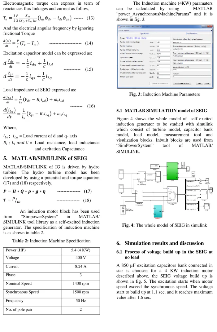
The Induction machine (4KW) paramaters can be calculated by using MATLAB “power_AsynchronousMachineParams” and it is shown in fig. 3.
Fig. 3: Induction Machine Parameters
5.1 MATLAB SIMULATION model of SEIG
Figure 4 shows the whole model of self excited induction generator to be studied with simulink which consist of turbine model, capacitor bank model, load model, measurement tool and visulization blocks. Inbuilt blocks are used from “SimPowerSystem” tool of MATLAB/ SIMULINK
.
Fig. 4: The whole model of SEIG in simulink
6. Simulation results and discussion
6.1 Process of voltage build up in the SEIG at no load
A 850 µF excitation capacitors bank connected in star is choosen for a 4 KW induction motor described above, the SEIG voltage build up is shown in fig. 5. The excitation starts when motor speed exceed the synchronous speed. The voltage start to build up at 1.1 sec. and it reaches maximum value after 1.6 sec.
Power (HP) 5.4 (4 KW) Voltage 400 V Current 8.24 A Phase 3 Nominal Speed 1430 rpm Synchronous Speed 1500 rpm Frequency 50 Hz
No. of pole pair 2
--- (15)
Fig. 5: SEIG voltage at no load
Figure 6 shows the electromagnetic torque at no load its stabilization lead for a terminal voltage to reach a stabilize peak value of -50 N-m.
Figure 7 shows that the current build up at stator terminal of SEIG at no load is 30 Amp. and the active power is depends on the load connected at SEIG terminal. As there is no any connected load, hence active power is zero, which is shown in fig. 8 below.
Fig. 6: Electromagnetic torque of SEIG at no load
Fig. 7: Stator current of SEIG at no load
Fig. 8: Output power of SEIG at no load
6.2 Process of voltage build up in the SEIG at full load
A 4 KW pure resistive load is connected across the SEIG, with constant value of 65µF excitation capacitor. More than 300V but less ihan rated voltage is contineously obtained as shown in figure 9, the voltage can be adjusted by increasing the speed of rotation in the shaft.
Figure 10 shows the full load active power output of SEIG. The SEIG delivers full load output power after 1.6 sec.
The electromagnetic torque of SEIG reaches its constant value of -24 N-m after 1.6 sec which is shown in figure 11.
Fig. 9: SEIG voltage at full load
Fig. 11: Full load torque of SEIG
Fig. 12: Full load current of SEIG
6.3 Process of voltage build up when SEIG at over load
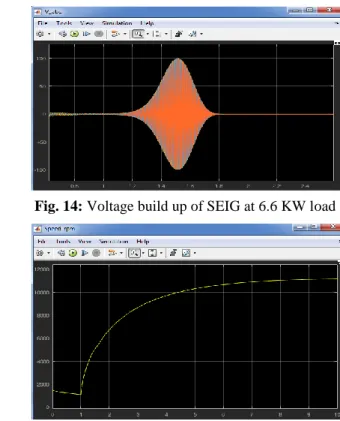
To observe the over loading condition of SEIG, constant value of 65µF excitation capacitor is connected across stator terminals and pure resistive load is gradually increased. It is observed that voltage build up continue till certain limits and then voltage collapse. Figure 13 shows that voltage build up is continue at 6.5 KW pure resistive load but when load changes to 6.6 KW voltage collapse as shown in figure 14.
From the figure 15 it observed that at over load condition when voltage collapse to zero the machine picks up dengerously high speed which cause machine itself and other connected equipment may damages.
Fig. 13: Voltage build up of SEIG at 6.5 KW load
Fig. 14: Voltage build up of SEIG at 6.6 KW load
Fig. 15: Speed of SEIG at 6.6 KW load
6.4 Process of voltage build up when load is Inductive
When inductive ( 1 kvar) full load is connected, electro-magnetic torque of -23.78 N-m is stablize after 1.8 sec. as shown in fig. 18 and voltage build up arround 380 V after 1.7 sec. as shown in fig. 16. Fig.17 and 19 shows load current and power respectively.
When inductive load is increased (4 kvar), SEIG terminal voltage build up after 2.6 sec. aproximately 500 V as shown in fig. 20 and load current also increased to 12 Amp. which is more than the rated current of machine as shown in fig. 22. electeo-magnetic torque -17.89 N-m is stablize after 2.6 sec before that it shows more transient as shown in fig. 21. Active power output increases and reactive power increases as shown in fig. 23.
Fig. 17: SEIG load current at Inductive load
Fig. 18: SEIG Electomagnetic torque at Inductive load
Fig. 19: SEIG active an reactive power of Inductive load
Fig. 20: SEIG voltage at Inductive (4 kvar) load
Fig. 21: Electro-magnetic torque at Inductive (4 kvar) load
Fig. 22: Load current at Inductive (4 kvar) load
Fig. 23: Active and reactive Power of Inductive (4 kvar) load
6.5 Process of voltage build up when load is Inductive and capacitive
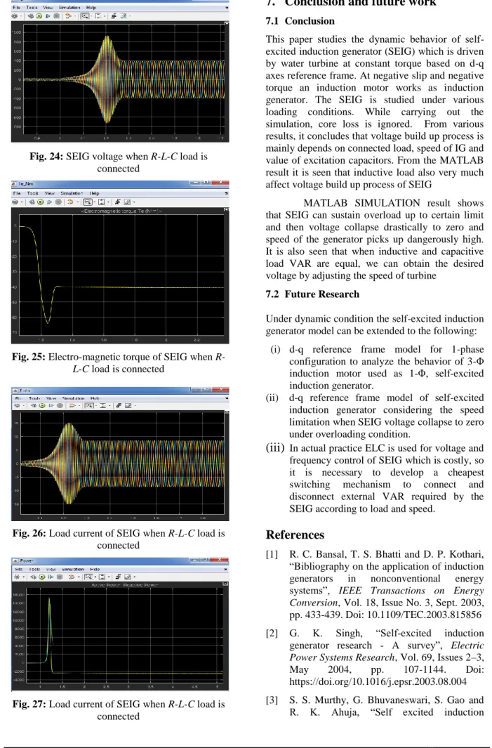
When R-L-C load of positive 4 kvar and negative 4 kvar is connected to the SEIG at full load, torque is stabilized -40.68 N-m after 1.27 sec. and voltage build up to 400 V as shown in fig 25 and fig. 24 respectively where as load current is 8.5 amp. and active power is 4.5 Kw as shown in fig. 26 and fig. 27 respectively.
Fig. 24: SEIG voltage when R-L-C load is connected
Fig. 25: Electro-magnetic torque of SEIG when R-L-C load is connected
Fig. 26: Load current of SEIG when R-L-C load is connected
Fig. 27: Load current of SEIG when R-L-C load is connected
7. Conclusion and future work
7.1 Conclusion
This paper studies the dynamic behavior of self-excited induction generator (SEIG) which is driven by water turbine at constant torque based on d-q axes reference frame. At negative slip and negative torque an induction motor works as induction generator. The SEIG is studied under various loading conditions. While carrying out the simulation, core loss is ignored. From various results, it concludes that voltage build up process is mainly depends on connected load, speed of IG and value of excitation capacitors. From the MATLAB result it is seen that inductive load also very much affect voltage build up process of SEIG
MATLAB SIMULATION result shows that SEIG can sustain overload up to certain limit and then voltage collapse drastically to zero and speed of the generator picks up dangerously high. It is also seen that when inductive and capacitive load VAR are equal, we can obtain the desired voltage by adjusting the speed of turbine
7.2 Future Research
Under dynamic condition the self-excited induction generator model can be extended to the following:
(i) d-q reference frame model for 1-phase configuration to analyze the behavior of 3-Φ induction motor used as 1-Φ, self-excited induction generator.
(ii) d-q reference frame model of self-excited induction generator considering the speed limitation when SEIG voltage collapse to zero under overloading condition.
(iii)
In actual practice ELC is used for voltage and frequency control of SEIG which is costly, so it is necessary to develop a cheapest switching mechanism to connect and disconnect external VAR required by the SEIG according to load and speed.References
[1] R. C. Bansal, T. S. Bhatti and D. P. Kothari, “Bibliography on the application of induction generators in nonconventional energy systems”, IEEE Transactions on Energy Conversion, Vol. 18, Issue No. 3, Sept. 2003, pp. 433-439. Doi: 10.1109/TEC.2003.815856 [2] G. K. Singh, “Self-excited induction
generator research - A survey”, Electric Power Systems Research, Vol. 69, Issues 2–3, May 2004, pp. 107-1144. Doi: https://doi.org/10.1016/j.epsr.2003.08.004 [3] S. S. Murthy, G. Bhuvaneswari, S. Gao and
generator for renewable energy applications to supply single-phase loads in remote locations”, 2010 IEEE International Conference on Sustainable Energy Technologies (ICSET), Kandy, 2010, pp. 1-8. Doi: 10.1109/ICSET.2010.5684947
[4] E. D. Bassett and F. M. Potter, “Capacitive Excitation for Induction Generators”, AIEE Trans. Electrical Engineering, Vol. 54, Issue No. 5, pp. 540 – 545, 1935.
[5] J. M. Elder, J. T. Boys and J. L. Woodward, “The process of self excitation in induction generators”, IEE Proceedings B - Electric Power Applications, Vol. 130, Issue No. 2, March 1983, pp. 103-108. Doi: 10.1049/ip-b.1983.0016
[6] C. F. Wagner, “Self-Excitation of Induction Motors With Series Capacitors”, Transactions of the American Institute of Electrical Engineers, Vol. 60, Issue No. 12, Dec. 1941, pp. 1241-1247. Doi: 10.1109/T-AIEE.1941.5058259
[7] M. B. Brennen and A. Abbondanti, “Static Exciters for Induction Generators”, IEEE Transactions on Industry Applications, Vol. IA-13, Issue No. 5, Sept. 1977, pp. 422-428. Doi: 10.1109/TIA.1977.4503433
[8] C. F. DeSieno and B. J. Beaudoin, “A Guide to the Application of Capacitors without Induction Motor Self-Excitation”, IEEE Transactions on Power Apparatus and Systems, Vol. 84, Issue No. 1, 1965. Doi: 10.1109/TPAS.1965.4766102
[9] H. P. Tiwari and J. K. Diwedi, “Minimum Capacitance Requirement for Self-Excited Induction Generator”, Proc. of National Power System Conference (NPSC 2002), Indian Institute of Technology, Kharagpur, December 27-29, 2002, pp. 5-10. Retrieved from
http://www.iitk.ac.in/npsc/Papers/NPSC2002/ 16.pdf
[10] N. H. Malik and A. A. Mazi, “Capacitance Requirements for Isolated Self Excited Induction Generators”, IEEE Transactions on Energy Conversion, Vol. EC-2, Issue No. 1, March 1987, pp. 62-69. Doi: 10.1109/TEC.1987.4765805
[11] M. Senthilkumar, “Optimal Capacitor for Maximum Output Power Tracking of Self Excited Induction Generator using Fuzzy Logic Approach”, International Journal on Computer Science and Engineering, Vol. 02, Issue No. 5, 2010, pp. 1758-1762. Retrieved from
https://pdfs.semanticscholar.org/f231/bd153c 5f102279384e1ff28737d960745c60.pdf [12] T. F. Chan, “Capacitance requirements of
self-excited induction generators”, IEEE Transactions on Energy Conversion, Vol. 8, Issue No. 2, June 1993, pp. 304-311. Doi: 10.1109/60.222721
[13] A. Kumari, A. G. Thosar and S. S. Mopari, “Determination of Excitation Capacitance of a Three Phase Self Excited Induction Generator”, International Journal of Advanced Research in Electrical, Electronics and Instrumentation Engineering, Vol. 4, Issue 5, May 2015, pp. 4069-4074. Retrieved from
http://www.ijareeie.com/upload/2015/may/38 _DETERMINATION.pdf
[14] A. K. Al Jabri and A. I. Alolah, “Capacitance requirement for insolated self-exicted induction generator”, IEE Proceedings B - Electric Power Applications, Vol. 137, Issue No. 3, May 1990, pp. 154-159. Doi: 10.1049/ip-b.1990.0016
[15] V. P. Chandran and S. Vadhera, “Capacitance requirements of self excited induction generator for different operating conditions”, Proc. of 2011 International Conference on Energy, Automation and Signal, Bhubaneswar, India. 28-31, Dec 2011, pp. 1-6. Doi: 10.1109/ICEAS.2011.6147177
[16] S. S. Murthy, R. Jose and B. Singh, “Experience in the Development of Microhydel Grid Independent Power Generation Scheme using Induction Generators for Indian Cconditions”, Proceedings of IEEE TENCON'98: IEEE Region 10 International Conference on Global Connectivity in Energy, Computer, Communication and Control (Cat. No. 98CH36229), New Delhi, India, 17-19 Dec. 1998, Vol. 2, pp. 461-465. Doi: https://doi.org/10.1109/TENCON.1998.79824 6
[17] B. Singh, S. S. Murthy, and S. Gupta, “STATCOM-Based Voltage Regulator for Self-Excited Induction Generator Feeding Nonlinear Loads”, IEEE Transactions on Industrial Electronics, Vol. 53, Issue No. 5,
2006, pp. 1437–1452. Doi:
10.1109/TIE.2006.882008
[18] B. Nia Roodsari, E. P. Nowicki and P. Freere, “An experimental investigation of the Distributed Electronic Load Controller: A new concept for voltage regulation in microhydro systems with transfer of excess power to household water heaters”, Proc. of 2014 IEEE Canada International
Humanitarian Technology Conference - (IHTC), Montreal, QC, 4 June 2014, pp. 1-4. Doi: 10.1109/IHTC.2011-4.7147548
[19] L. G. Scherer, C. B. Tischer, F. C. Posser, C. M. Franchi and R. F. de Camargo, “Hybrid topology for voltage regulation applied in three-phase four-wire micro hydro power station”, Proc. of IECON 2013 - 39th Annual Conference of the IEEE Industrial Electronics Society, Vienna, 2013, pp. 7169-7174. Doi: 10.1109/IECON.2013.6700324
[20] “Induction Generator | Application of Induction Generator”, Electrical4u.com.
[Online]. Available:
http://www.electrical4u.com/induction-generator/ (Accessed: Apr 24, 2018).
Authors’ Profile
Dinesh Kumar Mallik is
working as senior instructor in electrical department of “Council for Technical Education and Vocational Training” (CTEVT), Nepal. He
has completed his M.Tech. Degree in Electrical and Electronics Engineering from Assam Don Bosco University in 2018.
Jesif Ahmed is working as an Assistant Professor in the Department of Electrical and Electronics Engineering, School Of Technology, Assam Don Bosco University, Guwahati, Assam, India. He is pursuing his
Ph.D. from Gauhati University, Assam, India. His research interest includes study of electricity market, Power system optimization and transmission congestion management.