Programming manual
Retain for future use
Altivar 71
Variable speed drives for synchronous and
asynchronous motors
Specification 383
Software V2.4
Contents
Before you begin______________________________________________________________________________________________ 4 Documentation structure________________________________________________________________________________________ 5 Software enhancements ________________________________________________________________________________________ 6 Steps for setting up___________________________________________________________________________________________ 10 Factory configuration _________________________________________________________________________________________ 11 Application functions__________________________________________________________________________________________ 12 Setup - Preliminary recommendations ____________________________________________________________________________ 16 Graphic display terminal _______________________________________________________________________________________ 18 Description of terminal __________________________________________________________________________________ 18 Description of the graphic screen __________________________________________________________________________ 19 First power-up - [5. LANGUAGE] menu _____________________________________________________________________ 22 Subsequent power ups __________________________________________________________________________________ 23 Programming: Example of accessing a parameter_____________________________________________________________ 24 Quick navigation _______________________________________________________________________________________ 25 Integrated display terminal _____________________________________________________________________________________ 28 Functions of the display and the keys_______________________________________________________________________ 28 Accessing menus ______________________________________________________________________________________ 29 Accessing menu parameters _____________________________________________________________________________ 30 [2. ACCESS LEVEL] (LAC-) ____________________________________________________________________________________ 31 Structure of parameter tables ___________________________________________________________________________________ 34 Interdependence of parameter values ____________________________________________________________________________ 35 Finding a parameter in this document ____________________________________________________________________________ 36 [1.1 SIMPLY START] (SIM-)____________________________________________________________________________________ 37 [1.2 MONITORING] (SUP-) ____________________________________________________________________________________ 45 [1.3 SETTINGS] (SEt-) ________________________________________________________________________________________ 54 [1.4 MOTOR CONTROL] (drC-) _________________________________________________________________________________ 69 [1.5 INPUTS / OUTPUTS CFG] (I-O-) ___________________________________________________________________________ 101 [1.6 COMMAND] (CtL-)_______________________________________________________________________________________ 131 [1.7 APPLICATION FUNCT.] (FUn-) ____________________________________________________________________________ 144 [1.8 FAULT MANAGEMENT] (FLt-) _____________________________________________________________________________ 232 [1.9 COMMUNICATION] (COM-) _______________________________________________________________________________ 257 [1.10 DIAGNOSTICS] ________________________________________________________________________________________ 261 [1.11 IDENTIFICATION] ______________________________________________________________________________________ 264 [1.12 FACTORY SETTINGS] (FCS-) ____________________________________________________________________________ 265 [1.13 USER MENU] (USr-) ____________________________________________________________________________________ 268 [1.14 PROGRAMMABLE CARD] (PLC-) _________________________________________________________________________ 269 [3. OPEN/SAVE AS] _________________________________________________________________________________________ 270 [4. PASSWORD] (COd-)______________________________________________________________________________________ 272 [6 MONITORING CONFIG.] ___________________________________________________________________________________ 274 [7 DISPLAY CONFIG.] _______________________________________________________________________________________ 278 [MULTIPOINT SCREEN] _____________________________________________________________________________________ 283 Maintenance _______________________________________________________________________________________________ 284 Faults - Causes - Remedies ___________________________________________________________________________________ 285 User settings tables _________________________________________________________________________________________ 291 Index of functions ___________________________________________________________________________________________ 293 Index of parameter codes _____________________________________________________________________________________ 295
4
Before you begin
Read and understand these instructions before performing any procedure on this drive.
DANGER
HAZARDOUS VOLTAGE
• Read and understand the Installation Manual before installing or operating the ATV71 drive. Installation, adjustment, repair, and maintenance must be performed by qualified personnel.
• The user is responsible for compliance with all international and national electrical standards in force concerning protective grounding of all equipment.
• Many parts of this variable speed drive, including the printed circuit boards, operate at the line voltage. DO NOT TOUCH.
Use only electrically insulated tools.
• DO NOT touch unshielded components or terminal strip screw connections with voltage present. • DO NOT short across terminals PA/+ and PC/- or across the DC bus capacitors.
• Install and close all the covers before applying power or starting and stopping the drive. • Before servicing the variable speed drive
- Disconnect all power.
- Place a “DO NOT TURN ON” label on the variable speed drive disconnect. - Lock the disconnect in the open position.
• Disconnect all power including external control power that may be present before servicing the drive. WAIT 15 MINUTES to allow the DC bus capacitors to discharge. Then follow the DC bus voltage measurement procedure given in the Installation Manual to verify that the DC voltage is less than 45 V. The drive LEDs are not accurate indicators of the absence of DC bus voltage.
Electric shock will result in death or serious injury.
CAUTION
DAMAGED EQUIPMENT
Do not operate or install any drive that appears damaged.
Documentation structure
The following Altivar 71 technical documents are available on the Telemecanique website (www.telemecanique.com) as well as on the CD-ROM supplied with the drive.
Installation Manual
This describes how to assemble and connect the drive.
Programming manual
This describes the functions, parameters and use of the drive terminal (integrated display terminal and graphic display terminal). The communication functions are not described in this manual, but in the manual for the bus or network used.
Communication Parameters Manual
This manual describes:
• The drive parameters with specific information for use via a bus or communication network. • The operating modes specific to communication (state chart).
• The interaction between communication and local control.
Manuals for Modbus, CANopen, Ethernet, Profibus, INTERBUS, Uni-Telway, FIPIO
and Modbus Plus, etc.
These manuals describe the assembly, connection to the bus or network, signaling, diagnostics, and configuration of the communication-specific parameters via the integrated display terminal or the graphic display terminal.
6
Software enhancements
Since the Altivar ATV 71 was first launched, it has benefited from the addition of several new functions. Software version has now been updated to V2.4. The new version can be substituted to the previous versions without making any changes.
Although this documentation relates to version V2.4, it can still be used with previous versions, as the updates merely involves the addition of new values and parameters. None of the previous versions parameters have been modified or removed.
The software version is indicated on the nameplate attached to the body of the drive.
Enhancements made to version V1.2 in comparison to V1.1
Factory setting
Note 1: In version V1.1, the analog input was 0 ± 10 V. For safety reasons, in the new version this input has been set to 0 + 10 V. Note 2: In version V1.1, analog output AO1 was assigned to the motor frequency. In the new version, this output is not assigned at all.
With the exception of these two parameters, the factory settings of version V1.1 remain the same in the new version. The new functions are factory-set to disabled.
Motor frequency range
The maximum output frequency has been extended from 1000 to 1600 Hz (depending on the drive rating and control profile).
New parameters and functions
Menu
[1.2 MONITORING]
(SUP-)
Addition of internal states and values relating to the new functions described below.
Menu
[1.3 SETTINGS]
(SEt-)
• [High torque thd.](ttH) page 67. • [Low torque thd.](ttL) page 67. • [Pulse warning thd.](FqL) page 68. • [Freewheel stop Thd.](FFt) page68.
Menu
[1.4 MOTOR CONTROL]
(drC-)
• [rpm increment](InSP) page 76.
• Extension of the following configurations to all drive ratings; previously limited to 45 kW (60 HP) for ATV71pppM3X and to 75 kW (100 HP) for ATV71pppN4:synchronous motor [Sync. mot.](SYn) page 70, sinus filter [Sinus filter](OFI) page72, noise reduction
[Noise reduction](nrd) page 95, braking balance [Braking balance] (bbA) page 98.
Menu
[1.5 INPUTS / OUTPUTS CFG]
(I-O-)
• Input Al1 can now be configured to 0 +10 V or 0 ± 10 V via [AI1 Type] (AI1t) page 107. • [AI net. channel] (AIC1) page 111.
• New methods of assigning relays and logic outputs page 118: rope slack, high torque threshold, low torque threshold, motor in forward rotation, motor in reverse rotation, measured speed threshold reached, load variation detection.
• Analog output AO1 can now be used as a logic output and assigned to relay functions and logic outputs, page 123.
• New method of modifying the scale of analog outputs page 125 using the parameters [Scaling AOx min](ASLx) and [Scaling AOx max](ASHx).
• New methods of assigning logic outputs page 126: signed motor torque and measured motor speed.
• New methods of assigning alarm groups page 130: rope slack, high torque threshold, low torque threshold, measured speed threshold reached, load variation detection.
Software enhancements
Menu
[1.7 APPLICATION FUNCT.]
(Fun-)
• The summing, subtraction and multiplication reference functions can now be assigned to virtual input [Network AI] (AIU1) page 151. • New parameter [Freewheel stop Thd.] (FFt) page 156 used to set a threshold for switching to freewheel at the end of a stop on ramp
or fast stop.
• Brake engage at regulated zero speed [Brake engage at 0] (bECd) page 176.
• Weight [Weight sensor ass.] (PES) page 183 can now be assigned to virtual input [Network AI] (AIU1).
• New "rope slack" function page 187, with the parameters [Rope slack config.] (rSd) and [Rope slack trq level] (rStL). • Use of the ramp [Acceleration 2] (AC2) page 195 when starting and "waking up" the PID function.
• The torque limitation [TORQUE LIMITATION] (tOL-) page 202 can now be configured in whole % or in 0.1% increments using [Torque increment] (IntP) and assigned to virtual input [Network AI] (AIU1).
• New "stop at distance calculated after deceleration limit switch" function page 211, with the parameters [Stop distance] (Std),[Rated linear speed] (nLS) and [Stop corrector] (SFd).
• Positioning by sensors or limit switch [POSITIONING BY SENSORS] (LPO-) page 212 can now be configured in positive logic or negative logic using [Stop limit config. (SAL) and [Slowdown limit cfg.] (dAL).
• Parameter set switching [PARAM. SET SWITCHING] (MLP-) page 215 can now be assigned to the frequency thresholds attained
[Freq. Th. att.] (FtA) and [Freq. Th. 2 attain.] (F2A). • New half-floor: [HALF FLOOR] (HFF-) menu page 229.
Menu
[1.8 FAULT MANAGEMENT]
(FLt)
• Possibility of reinitializing the drive without turning it off, via [Product reset] (rP) page 235.
• Possibility of reinitializing the drive via a logic input without turning it off, using [Product reset assig.] (rPA) page 235.
• The possibility of configuring the "output phase loss" fault [Output Phase Loss] (OPL) page 240 to [Output cut] (OAC) has been extended to all drive ratings (previously limited to45 kW (60 HP) for ATV71pppM3X and 75 kW (100HP) for ATV71pppN4).
• The external fault [EXTERNAL FAULT] (EtF-) page 243 can now be configured in positive or negative logic via [External fault config.]
(LEt).
• New monitoring function based on speed measurement via "Pulse input" page 250, via the [FREQUENCY METER] (FqF-) menu. • New function for detecting load variation page 252, via the [DYNAMIC LOAD DETECT] (dLd-) menu.
• Short-circuit faults on the braking unit can now be configured via [Brake res. fault Mgt] (bUb) page 254.
Menu
[7 DISPLAY CONFIG.]
In [7.4 KEYPAD PARAMETERS]page 282, the [KEYPAD CONTRAST] and [KEYPAD STAND-BY] parameters to adjust the contrast and stand-by mode of the graphic display unit.
Enhancements made to version V1.3 (S383) in comparison to V1.2
New parameters and functions
Menu
[1.4 MOTOR CONTROL]
(drC-)
New option of operating with Closed-loop synchronous motor page 83
• [Angle auto-test] (ASA) page 84
• [Angle offset value] (ASU)page 85
• [Sync.CL](FSY) assignment page 71 of parameter [Motor control type] (Ctt)
Menu
[1.5 INPUTS / OUTPUTS CFG]
(I-O-)
• [Resolver Exct. Freq.] (FrES) and [Resolver poles nbr](rPPn) page 115
Menu
[1.7 APPLICATION FUNCT.]
(Fun-)
8
Software enhancements
Enhancements made to version V1.7 (S383) in comparison to V1.3 (S383)
New parameters and functions
Menu
[1.1 SIMPLY START]
(SIM-)
• Addition of a [Lift](LIFt) macro configuration to the [Macro configuration](CFG) parameter page 41
Menu
[1.3 SETTINGS]
(SEt-)
New parameters:
• [Fr.Loop.Stab](StA) page 56
• [FreqLoopGain](FLG) page 56
Menu
[1.4 MOTOR CONTROL]
(drC-)
This menu has been reorganized with parameters now appearing in a different order and some grouped under submenus to simplify configuration.
The new submenus are as follows:
• [ENCODER FEEDBACK](EnS-) page 75
• [ASYNC. MOTOR](ASY-) page 76
• [SYNCHRONOUS MOTOR](SYn-) page 81
• [ANGLE TEST SETTING](ASA-) page 84
• [FLUXING BY LI](FLI-) page 86
• [AUTOMATIC TUNE](tUn-) page 88
• [SPEED LOOP](SSL-) page 89
New parameters:
• [Boost](bOO) page 95
• [Action Boost](FAb) page 95
• [Increment EMF](IPHS) page 81
• [Read motor param.](rEqP) page 82
• [Status motor param](rEtP) page 82
• [Angle setting type](ASt) pages 84 and 87
• [Angle auto test](ASL) page 84
• [Angle setting activ.] (AtA) page 85
• [Angle setting status](AStS) page 85
• [Speed loop type] (SSL) page 89
• [Inertia Mult. Coef.](JMUL) page 89
• [Estim. app. inertia](JESt) page 89
• [Application Inertia](JAPL) page 90
• [Fr.Loop.Stab](StA) page 90
• [FreqLoopGain](FLG) page 90
• [Feed forward](FFP) page 91
• [Bandwidth feedfor.](FFU) page 91
Parameters moved from menu [1.7 APPLICATION FUNCT.](Fun-): • [Motor fluxing](FLU) page 86
• [Fluxing assignment](FLI) page 86
• [Auto-tune assign.](tUL) page 88
Menu
[1.5 INPUTS / OUTPUTS CFG]
(I-O-)
New encoder parameters:
• [Encoder protocol] (UECP) page 116
• [Encoder supply volt.] (UECU) page 116
• [Sincos lines count] (UELC) page 116
• [SSI parity] (SSCP) page 116
• [SSI frame size] (SSFS) page 116
• [Nbr of revolution] (EnMr) page 116
• [Turn bit resolution] (Entr) page 116
• [SSI code type] (SSCd) page 117
• [Encoder filter activ.] (FFA) page 117
• [Encoder filter value] (FFr) page 117
Menu
[1.7 APPLICATION FUNCT.]
(Fun-)
Removal of the following parameters (now located in the [1.4 MOTOR CONTROL](drC-) menu): • [Motor fluxing](FLU)
• [Fluxing assignment](FLI)
Software enhancements
Enhancements made to version V1.9 (S383) in comparison to V1.7 (S383)
New parameters and functions
Menu
[1.4 MOTOR CONTROL]
(drC-)
• New method of assigning [Angle setting type](ASt) page 87 : optimised measurement (without motion with memorization). New parameter :
• [App. Inertia Coef.](JACO) page 89.
Removal from the sub-menu [ASYNC. MOTOR] (ASY-) of the following parameters (now located directly in the
[1.4 MOTOR CONTROL](drC-) menu): • [Boost](bOO) page 95.
• [Action Boost](FAb) page 95.
Menu
[1.5 INPUTS / OUTPUTS CFG]
(I-O-)
New encoder parameters:
• [Coder rotation inv.] (EnrI) page 114. • [Clock frequency] (EnSP) page 117.
Menu
[1.7 APPLICATION FUNCT.]
(Fun-)
• New method of assigning for the parameters set switching [2 Parameter sets](CHA1) page 215 and [3 Parameter sets](CHA2)
page 215 : switching during braking sequence. This new assignment allows to put higher gain when the brake is open and before the starting of the ramp (useful for lift application).
New sub-menu:
• [TOP Z MANAGEMENT](tOP-) page 231 (the parameter can be accessed only if an encoder card VW 3A 411 has been inserted and if [Encoder type] (EnS) = [AABB] (AAbb).
New encoder parameter:
• [Stop on top Z] (tOSt) page 231.
Enhancements made to version V2.4 (S383) in comparison to V1.9 (S383)
New parameters and function
Menu
[1.7 APPLICATION FUNCT.]
(Fun-)
New sub-menu:
• [ROLLBACK MGT](rbM-) page 181. Menu can be accessed:
- only for ATV71pppM3X drives up to 45 kW and for ATV71pppN4 drives up to 75 kW, - if [Motor control type] (Ctt) page 70 = [Sync.CL] (FSY) or [FVC] (FUC),
- if [Brake assignment] (bLC) page 175 is assigned. New parameter of [ROLLBACK MGT] function:
• [Rollback MGT] (rbM) page 181. • [Rbk Compensation] (rbC) page 181. • [Rbk Damping] (rbd) page 181.
10
Steps for setting up
INSTALLATION
v
1
Consult the Installation Manual
PROGRAMMING
Procedure applicable if the factory configuration, page 11, and use of the
[SIMPLY START](SIM-) menu only are sufficient for the application.
b
2
Power up without run command
v
If you are using a separate power
supply for the control section, follow
the instructions on page
16
.
b
3
Select the language, if the drive
has a graphic display terminal
b
4
Configure the
[SIMPLY START]
(
SIM-
)
menu
v
2-wire or 3-wire control
v
Macro configuration
v
Motor parameters
)
Perform an auto-tuning
operation
v
Motor thermal current
v
Acceleration and deceleration
ramps
v
Speed variation range
Tips:
• Before you start programming, complete
the user setting tables, page
291
.
• Perform an auto-tuning operation to
optimize performance, page
43
.
• If you get lost, return to the factory
settings, page
267
.
Note: Check that the wiring of the
drive is compatible with its configuration.
b
5
Factory configuration
Drive factory settings
The Altivar 71 is factory-set for the most common operating conditions: • Macro configuration: Start/Stop
• Motor frequency: 50 Hz
• Constant torque application with asynchronous motor and sensorless flux vector control • Normal stop mode on deceleration ramp
• Stop mode in the event of a fault: freewheel
• Linear, acceleration and deceleration ramps: 3 seconds • Low speed: 0 Hz
• High speed: 50 Hz
• Motor thermal current = rated drive current
• Standstill injection braking current = 0.7 x rated drive current, for 0.5 seconds • No automatic starts after a fault
• Switching frequency 2.5 kHz or 4 kHz depending on drive rating • Logic inputs:
- LI1: forward, LI2: Forward (2 operating direction), 2-wire control on transition - L13, L14, LI5, LI6: inactive (not assigned)
• Analog inputs:
- AI1: speed reference 0 +10 V - AI2: 0-20 mA, inactive (not assigned)
• Relay R1: The contact opens in the event of a fault (or drive off). • Relay R2: Inactive (not assigned)
• Analog output AO1: 0-20 mA, inactive (not assigned)
If the above values are compatible with the application, the drive can be used without changing the settings.
Option card factory settings
12
Application functions
The tables on the following pages show the most common combinations of functions and applications, in order to guide your selection. The applications in these tables relate to the following machines in particular:
• Hoisting: cranes, overhead cranes, gantries (vertical hoisting, translation, slewing), lifting platforms • Elevators: elevators in retrofit up to 1.2 m/s
• Handling: palletizers/depalletizers, conveyors, roller tables • Packing: carton packers, labeling machines
• Textiles: weaving looms, carding frames, washing machines, spinners, drawing frames • Wood: automatic lathes, saws, milling
• High inertia: centrifuges, mixers, unbalanced machines (beam pumps, presses) • Process
Each machine has its own special features, and the combinations listed here are neither mandatory nor exhaustive.
Some functions are designed specifically for a particular application. In this case, the application is identified by a tab in the margin on the relevant programming pages.
Motor control functions
Functions Page Applications Hoisting Lifts Hand li ng Pack ing Texti le s W ood
High inertia Pro
c
ess
V/f ratio 70
b
b
b
Sensorless flux vector control 70
b
b
b
b
b
b
b
b
Flux vector control with sensor 70
b
b
b
b
b
b
b
b
2-point vector control 70
b
b
Open-loop synchronous motor 71
b
Closed-loop synchronous motor 71
b
b
b
Output frequency of up to 1600 Hz 76
b
b
Motor overvoltage limiting 96
b
b
DC bus connection (see User's Manual) -
b
b
Motor fluxing using a logic input 86
b
b
b
Switching frequency of up to 16 kHz 72
b
b
b
Application functions
Functions on speed references
Functions Page
Applications
Hoisting Lifts Hand
li ng Pa cki ng Te xtil es Wo od
High inertia Process
Differential bipolar reference 104
b
b
b
Reference delinearization (magnifying glass effect) 106
b
b
Frequency control input 140
b
b
Reference switching 141 - 150
b
Reference summing 149b
Reference subtraction 149b
Reference multiplication 149b
S ramps 152b
b
b
Jog operation 160b
b
b
Preset speeds 161b
b
b
b
b
+ speed/- speed using single action pushbuttons (1 step)
164
b
+ speed/- speed using double action pushbuttons (2 steps)
164
b
+/- speed around a reference 166
b
b
Save reference 168
b
14
Application functions
Application-specific functions
Functions Page
Applications
Hoisting Lifts Hand
li ng Pa cki ng Te xtil es Wo od
High inertia Process
Fast stop 156
b
b
Limit switch management 169
b
b
b
Brake control 171
b
b
b
Load measurement 182b
b
High-speed hoisting 184b
Rope slack 187b
PID regulator 189b
Torque monitoring 198b
b
b
Motor/generator torque limit 201
b
b
b
b
Load sharing 98
b
b
Line contactor control 205
b
b
b
Output contactor control 207
b
Positioning by limit switches or sensors 209
b
b
Stop at distance calculated after deceleration limit switch 211
b
b
ENA system (mechanical with unbalanced load) 93
b
Parameter switching 214
b
b
b
b
b
b
b
b
Motor or configuration switching 217
b
b
b
Traverse control 220
b
Stop configuration 156
b
b
b
b
Evacuation 229
b
Half floor 229
b
Application functions
Safety functions/fault management
Functions Page
Applications
Hoisting Lifts Hand
li ng Pa cki ng Te xtil es Wo od
High inertia Process
Power Removal (safety function, see User's Manual) -
b
b
b
b
b
b
b
b
Deferred stop on thermal alarm 242
b
Alarm handling 130
b
b
b
b
b
b
b
b
Fault management 233 to 256
b
b
b
b
b
b
b
b
IGBT tests 245
b
b
b
b
b
b
b
b
Catch a spinning load 237
b
b
b
Braking resistor thermal protection 254
b
b
b
b
Motor protection with PTC probes 233
b
b
b
b
b
b
b
b
Undervoltage management 244
b
b
b
4-20mA loss 246
b
b
b
b
b
b
Uncontrolled output cut (output phase loss) 240
b
Automatic restart 236
b
Use of the "Pulse input" input to measure the speed of rotation of the motor
250
b
b
b
16
Setup - Preliminary recommendations
Turning on and configuring the drive
Separate control section power supply
When the drive control section is powered independently of the power section (P24 and 0V terminals), whenever an option card is added or replaced, only the power section must be supplied with power next time the drive is powered up.
By default the new card would not be recognized and it would be impossible to configure it, thereby causing the drive to lock in fault mode.
Power switching via line contactor
User adjustment and extension of functions
• The display unit and buttons can be used to modify the settings and to extend the functions described in the following pages. • Return to factory settings is made easy by the [1.12 FACTORY SETTINGS](FCS-) menu, see page 265.
• There are three types of parameter: - Display: Values displayed by the drive
- Adjustment: Can be changed during operation or when stopped
- Configuration: Can only be modified when stopped and no braking is taking place. Can be displayed during operation.
DANGER
UNINTENDED EQUIPMENT OPERATION
• Before turning on and configuring the Altivar 71, check that the PWR (POWER REMOVAL) input is deactivated (at state 0) in order to prevent unintended operation.
• Before turning on the drive, or when exiting the configuration menus, check that the inputs assigned to the run command are deactivated (at state 0) since they can cause the motor to start immediately.
Failure to follow these instructions will result in death or serious injury.
CAUTION
INCOMPATIBLE LINE VOLTAGE
Before turning on and configuring the drive, ensure that the line voltage is compatible with the supply voltage range shown on the drive nameplate. The drive may be damaged if the line voltage is not compatible.
Failure to follow this instruction can result in equipment damage.
CAUTION
• Avoid operating the contactor frequently (premature ageing of the filter capacitors). • Cycle times < 60 s may result in damage to the pre-charge resistor.
Failure to follow this instruction can result in equipment damage.
DANGER
UNINTENDED EQUIPMENT OPERATION
• Check that changes made to the settings during operation do not present any danger. • We recommend stopping the drive before making any changes.
Setup - Preliminary recommendations
Starting
Important:
• In factory settings mode, the motor can only be supplied with power once the “forward”, “reverse” and “DC injection stop” commands have been reset:
- On power-up or a manual fault reset or after a stop command If they have not been reset, the drive will display "nSt" but will not start.
• If the automatic restart function has been configured ([Automatic restart](Atr) parameter in the [1.8-FAULT MANAGEMENT](FLt-)
menu, see page 236), these commands are taken into account without a reset being necessary.
Test on a low power motor or without a motor
• In factory settings mode, [Output Phase Loss] (OPL) detectionpage 240 is active (OPL = YES). To check the drive in a test or maintenance environment without having to switch to a motor with the same rating as the drive (particularly useful in the case of high power drives), deactivate [Output Phase Loss] (OPL = no).
• Configure [Motor control type] (Ctt) = [V/F 2pts](UF2) or [V/F 5pts](UF5) ([1.4-MOTOR CONTROL](drC-) menu, see page 70)
Using motors in parallel
• Configure [Motor control type] (Ctt) = [V/F 2pts](UF2) or [V/F 5pts](UF5) ([1.4-MOTOR CONTROL](drC-) menu, see page 70)
CAUTION
• Motor thermal protection will not be provided by the drive if the motor current is less than 0.2 times the rated drive current. Provide an alternative means of thermal protection.
Failure to follow this instruction can result in equipment damage.
CAUTION
• Motor thermal protection is no longer provided by the drive. Provide an alternative means of thermal protection on every motor.
18
Graphic display terminal
Although the graphic display terminal is optional for low-power drives, it is a standard component on high-power drives (see catalog). The graphic display terminal can be disconnected and connected remotely (on the door of an enclosure for example) using the cables and accessories available as options (see catalog).
Description of terminal
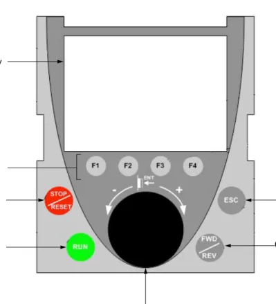
Note: Buttons 3, 4, 5 and 6 can be used to control the drive directly, if control via the terminal is activated.
Disconnected terminal
When the terminal is disconnected, 2 LEDs become visible:
1 Graphic display 2 Function keys F1, F2, F3, F4, see page 19. 3 STOP/RESET button 4 RUN button 5 Navigation button:
• Press (ENT): - To save the current value
- To enter the selected menu or parameter • Turn CW/
CCW:
- To increment or decrement a value - To go to the next or previous line
- To increase or decrease the reference if control via the terminal is activated
7 ESC key: Aborts a value, a parameter or a menu to return to the previous selection
6 Button for reversing the direction of rotation of the motor
HMI Modbus Green LED:
Graphic display terminal
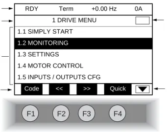
Description of the graphic screen
1. Display line. Its content can be configured; the factory settings show: • The drive state (see page 20)
• The active control channel: - Term: Terminals
- HMI: Graphic display terminal - MDB: Integrated Modbus - CAN: Integrated CANopen - NET: Communication card - APP: Controller Inside card • Frequency reference
• Current in the motor
2. Menu line. Indicates the name of the current menu or submenu.
3. Menus, submenus, parameters, values, bar charts, etc., are displayed in drop-down window format on a maximum of 5 lines. The line or value selected by the navigation button is displayed in reverse video.
4. Section displaying the functions assigned to the F1 to F4 keys and aligned with them, for example:
The function keys are dynamic and contextual.
Other functions (application functions) can be assigned to these keys via the [1.6 COMMAND] menu.
5. Indicates that there are no more levels below this display window. Indicates that there are more levels below this display window.
6. Indicates that this display window does not scroll further up. Indicates that there are more levels above this display window.
: Displays the code of the selected parameter, i.e., the code corresponding to the 7-segment display. : Contextual help
: Navigate horizontally to the left, or go to previous menu/submenu or, for a value, go to the next digit up, displayed in reverse video (see the example on page 21).
: Navigate horizontally to the right or go to next menu/submenu (going to the [2 ACCESS LEVEL] menu in this example) or, for a value, go to the next digit down, displayed in reverse video (see the example on page 21).
: Quick navigation, see page 25.
F1
F2
F3
F4
RDY Term +0.00 Hz 0A 1 DRIVE MENU 1.1 SIMPLY START 1.2 MONITORING 1.3 SETTINGS 1.4 MOTOR CONTROL 1.5 INPUTS / OUTPUTS CFG Code << >> Quick 1 2 3 4 6 5 • Code F1 • HELP F1 • << F2 • >> F3 • Quick F420
Graphic display terminal
Drive state codes:
- ACC: Acceleration - CLI: Current limit
- CTL: Controlled stop on input phase loss - DCB: DC injection braking in progress - DEC: Deceleration
- FLU: Motor fluxing in progress - FST: Fast stop
- NLP: No line power (no line supply on L1, L2, L3) - NST: Freewheel stop
- OBR: Auto-adapted deceleration
- PRA: Power Removal function active (drive locked) - RDY: Drive ready
- RUN: Drive running
- SOC: Controlled output cut in progress - TUN: Auto-tuning in progress
- USA: Undervoltage alarm
Graphic display terminal
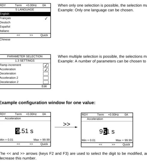
Example configuration windows:
Example configuration window for one value:
The << and >> arrows (keys F2 and F3) are used to select the digit to be modified, and the navigation button is rotated to increase or decrease this number.
When only one selection is possible, the selection made is indicated by Example: Only one language can be chosen.
When multiple selection is possible, the selections made are indicated by Example: A number of parameters can be chosen to form the [USER MENU].
RDY Term +0.00Hz 0A 5 LANGUAGE English Français Deutsch Español Italiano << >> Quick Chinese PARAMETER SELECTION 1.3 SETTINGS Ramp increment Acceleration Deceleration Acceleration 2 Deceleration 2 Edit RDY Term +0.00Hz 0A Acceleration
9
.51 s
Min = 0.01 Max = 99.99 << >> Quick>>
RDY Term +0.00Hz 0A Acceleration9
5
1 s
Min = 0.01 Max = 99.99 << >> Quick22
Graphic display terminal
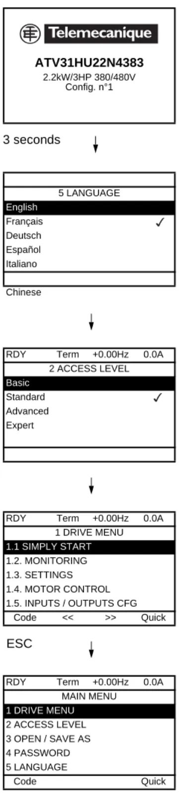
First power-up - [5. LANGUAGE] menu
The first time the drive is powered up, the user will automatically be guided through the menus as far as [1. DRIVE MENU].
The parameters in the [1.1 SIMPLY START] submenu must be configured and auto-tuning performed before the motor is started up.
Display for 3 seconds following power-up
3 seconds
Automatically switches to [5 LANGUAGE] menu 3 seconds later.
Select the language and press ENT.
Switches to [2 ACCESS LEVEL] menu (see page 31)
Select the access level and press ENT.
Switches to [1 DRIVE MENU] (see page 27)
ESC
Press ESC to return to [MAIN MENU] ATV31HU22N4383 2.2kW/3HP 380/480V Config. n°1 5 LANGUAGE English Français Deutsch Español Italiano Chinese
RDY Term +0.00Hz 0.0A
2 ACCESS LEVEL
Basic
Standard Advanced Expert
RDY Term +0.00Hz 0.0A
1 DRIVE MENU 1.1 SIMPLY START 1.2. MONITORING 1.3. SETTINGS 1.4. MOTOR CONTROL 1.5. INPUTS / OUTPUTS CFG Code << >> Quick
RDY Term +0.00Hz 0.0A
MAIN MENU 1 DRIVE MENU 2 ACCESS LEVEL 3 OPEN / SAVE AS 4 PASSWORD 5 LANGUAGE Code Quick
Graphic display terminal
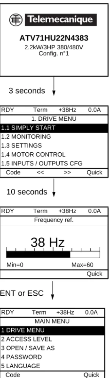
Subsequent power ups
Switches to [1. DRIVE MENU] 3 seconds later.
If no operator inputs are made, switches to "Display" automatically 10 seconds later (the display will vary depending on the selected configuration).
Users can return to [MAIN MENU] by pressing ENT or ESC. 3 seconds 10 seconds ENT or ESC ATV71HU22N4383 2.2kW/3HP 380/480V Config. n°1
RDY Term +38Hz 0.0A
1. DRIVE MENU 1.1 SIMPLY START 1.2 MONITORING 1.3 SETTINGS 1.4 MOTOR CONTROL 1.5 INPUTS / OUTPUTS CFG Code << >> Quick
RDY Term +38Hz 0.0A
Frequency ref.
Min=0 Max=60
Quick
RDY Term +38Hz 0.0A
MAIN MENU 1 DRIVE MENU 2 ACCESS LEVEL 3 OPEN / SAVE AS 4 PASSWORD 5 LANGUAGE Code Quick
38 Hz
24
Graphic display terminal
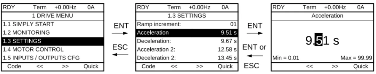
Programming: Example of accessing a parameter
Accessing the acceleration ramp
Note:
• To select a parameter:
- Turn the navigation button to scroll vertically. • To modify a parameter:
- Use the << and >> keys (F2 and F3) to scroll horizontally and select the digit to be modified (the selected digit changes to white on a black background).
- Turn the navigation button to modify the digit. • To cancel the modification:
- Press ESC.
• To save the modification:
- Press the navigation button (ENT).
RDY Term +0.00Hz 0A 1 DRIVE MENU 1.1 SIMPLY START 1.2 MONITORING 1.3 SETTINGS 1.4 MOTOR CONTROL 1.5 INPUTS / OUTPUTS CFG Code << >> Quick ENT ESC RDY Term +0.00Hz 0A 1.3 SETTINGS Ramp increment: 01 Acceleration 9.51 s Deceleration: 9.67 s Acceleration 2: 12.58 s Deceleration 2: 13.45 s Code << >> Quick ENT ENT or ESC RDY Term +0.00Hz 0A Acceleration
9.
5
1 s
Min = 0.01 Max = 99.99 << >> QuickGraphic display terminal
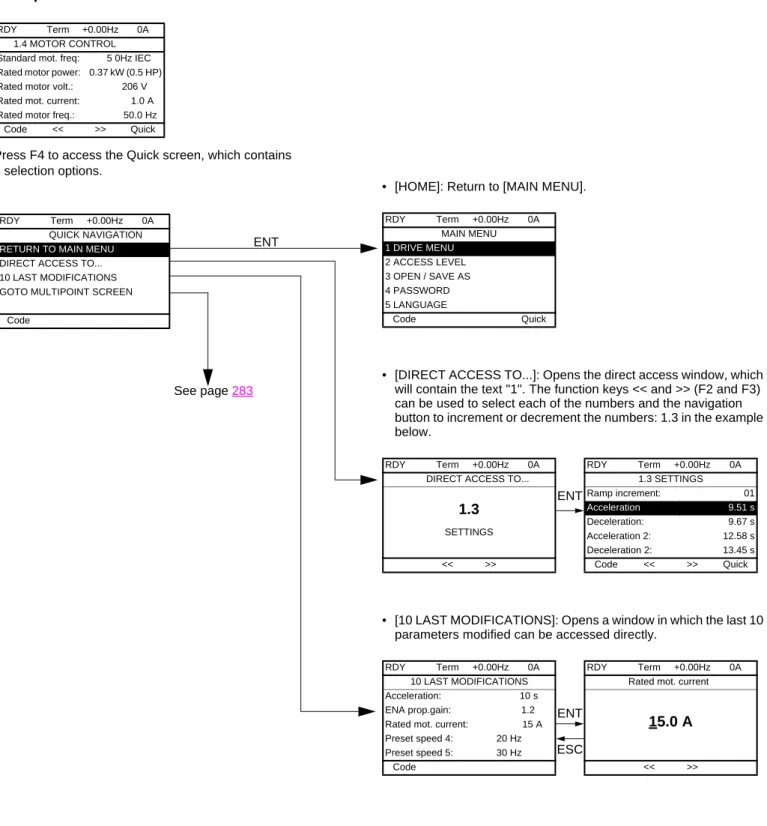
Quick navigation
If the "Quick" function is displayed above the F4 key, you can gain quick access to a parameter from any screen.
Example:
Press F4 to access the Quick screen, which contains 4 selection options.
• [HOME]: Return to [MAIN MENU].
• [DIRECT ACCESS TO...]: Opens the direct access window, which will contain the text "1". The function keys << and >> (F2 and F3) can be used to select each of the numbers and the navigation button to increment or decrement the numbers: 1.3 in the example below.
• [10 LAST MODIFICATIONS]: Opens a window in which the last 10 parameters modified can be accessed directly.
RDY Term +0.00Hz 0A
1.4 MOTOR CONTROL Standard mot. freq: 5 0Hz IEC Rated motor power: 0.37 kW (0.5 HP) Rated motor volt.: 206 V Rated mot. current: 1.0 A Rated motor freq.: 50.0 Hz
Code << >> Quick
ENT
RDY Term +0.00Hz 0A
QUICK NAVIGATION
RETURN TO MAIN MENU
DIRECT ACCESS TO... 10 LAST MODIFICATIONS GOTO MULTIPOINT SCREEN
Code See page 283 RDY Term +0.00Hz 0A MAIN MENU 1 DRIVE MENU 2 ACCESS LEVEL 3 OPEN / SAVE AS 4 PASSWORD 5 LANGUAGE Code Quick RDY Term +0.00Hz 0A
DIRECT ACCESS TO...
1.3
SETTINGS << >> ENT RDY Term +0.00Hz 0A 1.3 SETTINGS Ramp increment: 01 Acceleration 9.51 s Deceleration: 9.67 s Acceleration 2: 12.58 s Deceleration 2: 13.45 s Code << >> Quick RDY Term +0.00Hz 0A 10 LAST MODIFICATIONS Acceleration: 10 s ENA prop.gain: 1.2 Rated mot. current: 15 A Preset speed 4: 20 Hz Preset speed 5: 30 Hz Code ESC ENT RDY Term +0.00Hz 0ARated mot. current
15.0 A
26
Graphic display terminal
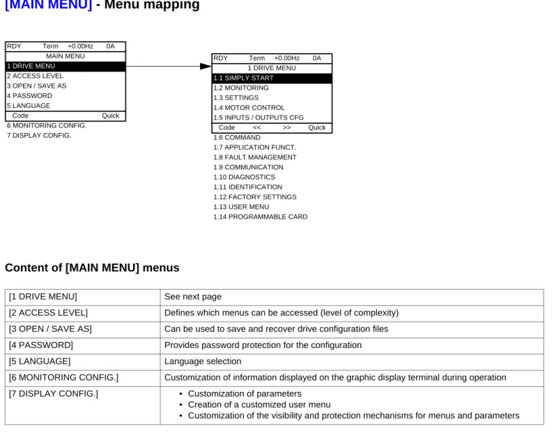
[MAIN MENU]
- Menu mapping
Content of [MAIN MENU] menus
[1 DRIVE MENU] See next page
[2 ACCESS LEVEL] Defines which menus can be accessed (level of complexity) [3 OPEN / SAVE AS] Can be used to save and recover drive configuration files [4 PASSWORD] Provides password protection for the configuration
[5 LANGUAGE] Language selection
[6 MONITORING CONFIG.] Customization of information displayed on the graphic display terminal during operation [7 DISPLAY CONFIG.] • Customization of parameters
• Creation of a customized user menu
• Customization of the visibility and protection mechanisms for menus and parameters
RDY Term +0.00Hz 0A MAIN MENU 1 DRIVE MENU 2 ACCESS LEVEL 3 OPEN / SAVE AS 4 PASSWORD 5 LANGUAGE Code Quick 6 MONITORING CONFIG. 7 DISPLAY CONFIG. RDY Term +0.00Hz 0A 1 DRIVE MENU 1.1 SIMPLY START 1.2 MONITORING 1.3 SETTINGS 1.4 MOTOR CONTROL 1.5 INPUTS / OUTPUTS CFG Code << >> Quick 1.6 COMMAND 1.7 APPLICATION FUNCT. 1.8 FAULT MANAGEMENT 1.9 COMMUNICATION 1.10 DIAGNOSTICS 1.11 IDENTIFICATION 1.12 FACTORY SETTINGS 1.13 USER MENU 1.14 PROGRAMMABLE CARD
Graphic display terminal
[1 DRIVE MENU]
Content of [1. DRIVE MENU] menus:
RDY Term +0.00Hz 0A 1 DRIVE MENU 1.1 SIMPLY START 1.2 MONITORING 1.3 SETTINGS 1.4 MOTOR CONTROL 1.5 INPUTS / OUTPUTS CFG Code << >> Quick 1.6 COMMAND 1.7 APPLICATION FUNCT. 1.8 FAULT MANAGEMENT 1.9 COMMUNICATION 1.10 DIAGNOSTICS 1.11 IDENTIFICATION 1.12 FACTORY SETTINGS 1.13 USER MENU 1.14 PROGRAMMABLE CARD
[1.1 SIMPLY START]: Simplified menu for a quick start
[1.2 MONITORING]: Visualization of current, motor and input/output values
[1.3 SETTINGS]: Accesses the adjustment parameters, which can be modified during operation
[1.4 MOTOR CONTROL]: Motor parameters (motor nameplate, auto-tuning, switching frequency, control algorithms, etc.) [1.5 INPUTS / OUTPUTS CFG]: I/O configuration (scaling, filtering, 2-wire control, 3-wire control, etc.)
[1.6 COMMAND]: Configuration of command and reference channels (graphic display terminal, terminals, bus, etc.) [1.7 APPLICATION FUNCT.]: Configuration of application functions (e.g., preset speeds, PID, brake logic control, etc.)
[1.8 FAULT MANAGEMENT]: Configuration of fault management [1.9 COMMUNICATION]: Communication parameters (fieldbus) [1.10 DIAGNOSTICS]: Motor/drive diagnostics
[1.11 IDENTIFICATION]: Identifies the drive and the internal options
[1.12 FACTORY SETTINGS]: Access to configuration files and return to factory settings
[1.13 USER MENU]: Specific menu set up by the user in the [7. DISPLAY CONFIG.] menu [1.14 PROGRAMMABLE CARD]: Configuration of optional Controller Inside card
28
Integrated display terminal
Low-power Altivar 71 drives (see catalog) feature an integrated display terminal with a 7-segment 4-digit display. The graphic display terminal described on the previous pages can also be connected to these drives as an option.
Functions of the display and the keys
• Pressing or does not store the selection.
• Press and hold down (>2 s) or to scroll through the data quickly. Save and store the selection: ENT
The display flashes when a value is stored.
Normal display, with no fault present and no startup:
- 43.0: Display of the parameter selected in the SUP menu (default selection: motor frequency) - CLI: Current limit
- CtL: Controlled stop on input phase loss - dCb: DC injection braking in progress - FLU: Motor fluxing in progress - FSt: Fast stop.
- nLP: No line power (no line supply on L1, L2, L3) - nSt: Freewheel stop
- Obr: Auto-adapted deceleration
- PrA: Power Removal function active (drive locked) - rdY = Drive ready
- SOC: Controlled output cut in progress - tUn: Auto-tuning in progress
- USA: Undervoltage alarm
- ASA: Measurement of the phase-shift angle in progress The display flashes to indicate the presence of a fault.
• Four 7-segment displays
• Enters a menu or parameter, or saves the displayed parameter or value
• Returns to the previous menu or parameter, or increases the displayed value
• Exits a menu or parameter, or aborts the displayed value to return to the previous value in the memory
• Goes to the next menu or parameter, or decreases the displayed value
• 2 CANopen status LEDs • 2 Modbus status LEDs
Integrated display terminal
Accessing menus
A dash appears after menu and submenu codes to differentiate them from parameter codes. Examples: FUn- menu, ACC parameter.
The grayed-out menus may not be accessible depending on the control access (LAC) configuration. XXX CtL- FUn- SIM- I-O- SEt- SUP-ESC ESC ESC ESC ESC ESC ESC ESC ENT ENT ESC ENT ESC ENT ESC ENT ESC ENT ESC ENT ESC ENT ESC FCS- LAC- CON- FLt-ESC ESC ESC ESC ENT ESC ENT ESC ENT ESC ENT ESC ENT ESC SPL-ESC ENT ESC drC- COd- USr-ESC ENT ESC
Displays the state of the drive
SETTINGS APPLICATION FUNCT. INPUTS / OUTPUTS CFG FAULT MANAGEMENT SIMPLY START Menus MONITORING MOTOR CONTROL COMMAND Power-up FACTORY SETTINGS PASSWORD ACCESS LEVEL COMMUNICATION
(page 54) Adjustment parameters, can be modified during operation
(page 144)Configuration of application functions (e.g., preset speeds, PID, brake logic control, etc.)
(page 101) I/O configuration (scaling, filtering, 2-wire control, 3-wire control, etc.)
(page 232) Configuration of fault management (page 37) Simplified menu for fast startup
(page 45) Visualization of current, motor and input/output values
(page 71) Motor parameters (motor nameplate, auto-tuning, switching frequency, control algorithms, etc.)
(page 131) Configuration of command and reference channels (graphic display terminal, terminals, bus, etc.)
(page 265) Access to configuration files and return to factory settings
(page 272)
(page 31)
(page 257) Communication parameters (fieldbus)
(page 268) Specific menu, set up by the user using the graphic display terminal.
USER MENU
30
Integrated display terminal
Accessing menu parameters
Save and store the displayed selection :
The display flashes when a value is stored.
All the menus are "drop-down" type menus, which means that after the last parameter, if you continue to press , you will return to the first parameter and, conversely, you can switch from the first parameter to the last parameter by pressing .
Selection of multiple assignments for one parameter
Example: List of group 1 alarms in [INPUTS / OUTPUTS CFG]
(I-O-) menu
A number of alarms can be selected by "checking" them as follows.
The digit on the right indicates: selected not selected. The same principle is used for all multiple selections. ENT ACC 15.0 ENT ESC ENT ESC 26.0 26.0 ESC dEC ENT
SEt-Menu Value or assignment
1 flash (save) Parameter (Next parameter) ENT ESC 1st nth last Menu ENT ESC
I-O-Alarm not selected Alarm selected
[2. ACCESS LEVEL]
(LAC-)
With graphic display terminal
Basic
Access to 5 menus only, and access to 6 submenus only in the [1. DRIVE MENU] menu.
A single function can be assigned to each input.
Standard
This is the factory-set level. Access to 6 menus only, and access to all submenus in the [1. DRIVE MENU] menu.
A single function can be assigned to each input.
Advanced
Access to all menus and submenus. Several functions can be assigned to each input.
Expert
Access to all menus and submenus as for [Advanced] level, and access to additional parameters.
Several functions can be assigned to each input.
RDY Term +0.00Hz 0A 2 ACCESS LEVEL Basic Standard Advanced Expert << >> Quick RDY Term +0.00Hz 0A MAIN MENU 1 DRIVE MENU 2 ACCESS LEVEL 3 OPEN / SAVE AS 4 PASSWORD 5 LANGUAGE Code << >> Quick RDY Term +0.00Hz 0A 1. DRIVE MENU 1.1 SIMPLY START 1.2. MONITORING 1.3. SETTINGS 1.11. IDENTIFICATION 1.12. FACTORY SETTINGS Code << >> Quick 1.13 USER MENU RDY Term +0.00Hz 0A MAIN MENU 1 DRIVE MENU 2 ACCESS LEVEL 3 OPEN / SAVE AS 4 PASSWORD 5 LANGUAGE Code Quick 6 MONITORING CONFIG. RDY Term +0.00Hz 0A 1 DRIVE MENU 1.1 SIMPLY START 1.2 MONITORING 1.3 SETTINGS 1.4 MOTOR CONTROL 1.5 INPUTS / OUTPUTS CFG Code << >> Quick 1.6 COMMAND 1.7 APPLICATION FUNCT. 1.8 FAULT MANAGEMENT 1.9 COMMUNICATION 1.10 DIAGNOSTICS 1.11 IDENTIFICATION 1.12 FACTORY SETTINGS 1.13 USER MENU 1.14 PROGRAMMABLE CARD RDY Term +0.00Hz 0A MAIN MENU 1 DRIVE MENU 2 ACCESS LEVEL 3 OPEN / SAVE AS 4 PASSWORD 5 LANGUAGE Code Quick 6 MONITORING CONFIG. 7 DISPLAY CONFIG. RDY Term +0.00Hz 0A MAIN MENU 1 DRIVE MENU 2 ACCESS LEVEL 3 OPEN / SAVE AS 4 PASSWORD 5 LANGUAGE Code Quick 6 MONITORING CONFIG. 7 DISPLAY CONFIG.
32
[2. ACCESS LEVEL]
(LAC-)
With integrated display terminal:
Code Name/Description Factory setting
LAC- Std
bAS Std Adu Epr
• bAS: Limited access to SIM, SUP, SEt, FCS, USr, COd and LAC menus. Only one function can be assigned to each input.
• Std: Access to all menus on the integrated display terminal. Only one function can be assigned to each input. • AdU: Access to all menus on the integrated display terminal. Several functions can be assigned to each input. • EPr: Access to all menus on the integrated display terminal and access to additional parameters. Several functions
can be assigned to each input. XXX SIM-ESC ESC ENT LAC-ESC ENT ESC
COd-Displays the state of the drive
ACCESS LEVEL Power-up
[2. ACCESS LEVEL]
(LAC-)
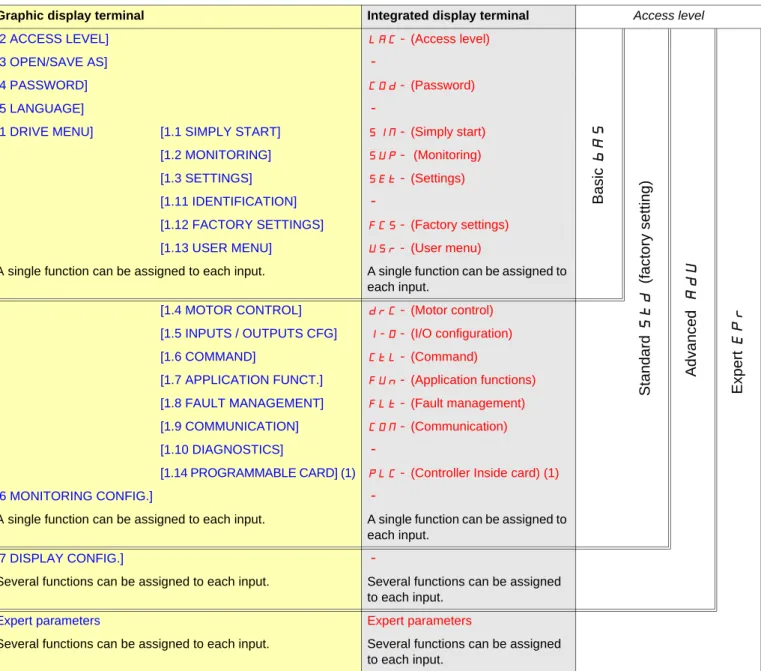
Comparison of the menus that can be accessed on the graphic display terminal/
integrated display terminal
(1) Can be accessed if the Controller Inside card is present.
Graphic display terminal Integrated display terminal Access level
[2 ACCESS LEVEL] LAC- (Access level)
Basic
bA
S
Stan
dar
d
St
d
(factory
setting)
Ad
va
nc
ed
AdU
Exper
t
EP
r
[3 OPEN/SAVE AS]-[4 PASSWORD] COd- (Password)
[5 LANGUAGE]
-[1 DRIVE MENU] [1.1 SIMPLY START] SIM- (Simply start)
[1.2 MONITORING] SUP- (Monitoring)
[1.3 SETTINGS] SEt- (Settings)
[1.11 IDENTIFICATION]
-[1.12 FACTORY SETTINGS] FCS- (Factory settings)
[1.13 USER MENU] USr- (User menu)
A single function can be assigned to each input. A single function can be assigned to each input.
[1.4 MOTOR CONTROL] drC- (Motor control)
[1.5 INPUTS / OUTPUTS CFG] I-O- (I/O configuration)
[1.6 COMMAND] CtL- (Command)
[1.7 APPLICATION FUNCT.] FUn- (Application functions)
[1.8 FAULT MANAGEMENT] FLt- (Fault management)
[1.9 COMMUNICATION] COM- (Communication)
[1.10 DIAGNOSTICS]
-[1.14 PROGRAMMABLE CARD] (1) PLC- (Controller Inside card) (1)
[6 MONITORING CONFIG.]
-A single function can be assigned to each input. A single function can be assigned to each input.
[7 DISPLAY CONFIG.]
-Several functions can be assigned to each input. Several functions can be assigned to each input.
Expert parameters Expert parameters
Several functions can be assigned to each input. Several functions can be assigned to each input.
34
Structure of parameter tables
The parameter tables in the descriptions of the various menus can be used with both the graphic display terminal and the integrated display terminal. They, therefore, contain information for these two terminals in accordance with the description below.
Example:
[1.7 APPLICATION FUNCT.]
(FUn-)
Code Name/Description Adjustment range Factory setting
UPd-
b
[+/- SPEED]
Function can be accessed for reference channel [Ref.2 channel] (Fr2) = [+/- speed] (UPdt) , see page 141
USP
M
[+ speed assignment]
[No] (nO)no LI1
v
[No]
(nO): function inactivev
[LI1]
(LI1)
Note:
• The text in square brackets [ ] indicates what you will see on the graphic display terminal.
• The factory settings correspond to [Macro configuration](CFG) = [Start/Stop](StS). This is the macro configuration set at the factory. 5 2 3 1 4 6 8 7
1. Name of menu on 4-digit 7-segment display.
2. Submenu code on 4-digit 7-segment display.
3. Parameter code on 4-digit 7-segment display.
4. Parameter value on 4-digit 7-segment display.
5. Name of menu on graphic display terminal.
6. Name of submenu on graphic display terminal.
7. Name of parameter on graphic display terminal.
Interdependence of parameter values
The configuration of certain parameters modifies the adjustment range of other parameters, in order to reduce the risk of errors. This may result in the modification of a factory setting or a value you have already selected.
Example:
1. [Current Limitation] (CLI) page 62 set to 1.6 In or left at its factory setting, 1.5 In
2. [Switching freq.] (SFr) page 62 set to 1 kHz (and confirmed with "ENT") restricts [Current Limitation] (CLI) to 1.36 In
3. If [Switching freq.] (SFr) is increased to 4 kHz, [Current limitation] (CLI) is no longer restricted, but remains at 1.36 In. If you require 1.6 In, you must reset [Current Limitation] (CLI).
36
Finding a parameter in this document
The following assistance with finding explanations on a parameter is provided:
• With the integrated display terminal: Direct use of the parameter code index, page 295, to find the page giving details of the displayed parameter.
• With the graphic display terminal: Select the required parameter and press : [Code]. The parameter code is displayed instead of its name while the key is held down.
Example: ACC
Then use the parameter code index, page 295, to find the page giving details of the displayed parameter. F1 RDY Term +0.00Hz 0A 1.3 SETTINGS Ramp increment: 01 Acceleration 9.51 s Deceleration: 9.67 s Acceleration 2: 12.58 s Deceleration 2: 13.45 s Code << >> Quick Code RDY Term +0.00Hz 0A 1.3 SETTINGS Ramp increment: 01 ACC 9.51 s Deceleration: 9.67 s Acceleration 2: 12.58 s Deceleration 2: 13.45 s Code << >> Quick
[1.1 SIMPLY START]
(SIM-)
With graphic display terminal:
With integrated display terminal:
The [1.1-SIMPLY START](SIM-) menu can be used for fast startup, which is sufficient for the majority of applications.
The parameters in this menu can only be modified when the drive is stopped and no run command is present, with the following exceptions: • Auto-tuning, which causes the motor to start up
• The adjustment parameters on page 44
The [1.1 SIMPLY START](SIM-) menu should be configured on its own or before the other drive configuration menus. If a modification has previously been made to any of them, in particular in [1.4 MOTOR CONTROL](drC-), some [1.1 SIMPLY START](SIM-) parameters may be changed, for example, the motor parameters, if a synchronous motor has been selected. Returning to the [1.1 SIMPLY START]
(SIM-) menu after modifying another drive configuration menu is unnecessary but does not pose any risk. Changes following modification of another configuration menu are not described, to avoid unnecessary complication in this section.
Macro configuration
Macro configuration provides a means of speeding up the configuration of functions for a specific field of application. 8 macro configurations are available:
• Start/stop (factory configuration) • Handling • General use • Hoisting • Lifts • PID regulator • Communication bus • Master/slave
Selecting a macro configuration assigns the parameters in this macro configuration. Each macro configuration can still be modified in the other menus.
Note: The parameters of the [1.1 SIMPLY START](SIM-) menu must be entered in the order in which they appear, as the later ones are dependent on the first ones.
For example [2/3 wire control](tCC) must be configured before any other parameters.
RDY Term +0.00Hz 0A MAIN MENU 1 DRIVE MENU 2 ACCESS LEVEL 3 OPEN / SAVE AS 4 PASSWORD 5 LANGUAGE Code Quick ENT RDY Term +0.00Hz 0A 1 DRIVE MENU 1.1 SIMPLY START 1.2 MONITORING 1.3 SETTINGS 1.4 MOTOR CONTROL 1.5 INPUTS / OUTPUTS CFG Code << >> Quick ENT
RUN Term +50.00Hz 80A
1.1 SIMPLY START
2/3 wire control
Macro configuration Customized macro Standard mot. freq Input phase loss
Code << >> Quick XXX SIM- SUP-ESC ESC ESC ENT ENT ESC
LAC-Displays the state of the drive
SIMPLY START Power-up
38
[1.1 SIMPLY START]
(SIM-)
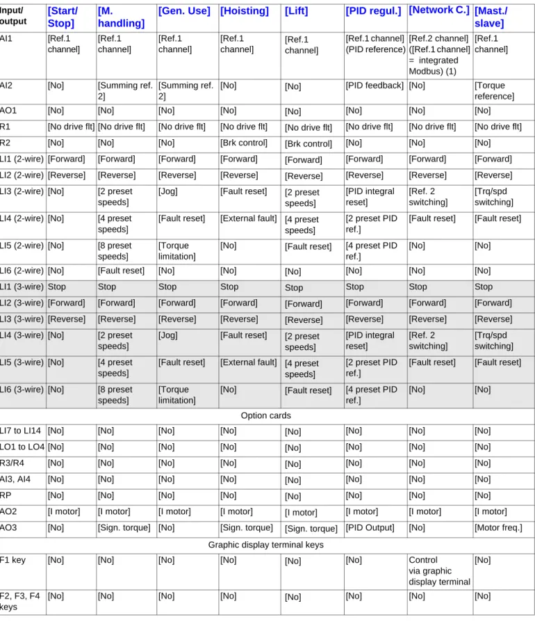
Macro configuration parameters
Assignment of the inputs/outputs
(1) To start up with integrated Modbus, [Modbus Address](Add) must first be configured, page 259. Note: These assignments are reinitialized every time the macro configuration changes.
Input/ output
[Start/
Stop]
[M.
handling]
[Gen. Use]
[Hoisting]
[Lift]
[PID regul.] [Network C.]
[Mast./
slave]
AI1 [Ref.1 channel] [Ref.1 channel] [Ref.1 channel] [Ref.1 channel] [Ref.1 channel] [Ref.1 channel] (PID reference) [Ref.2 channel] ([Ref.1 channel] = integrated Modbus) (1) [Ref.1 channel]AI2 [No] [Summing ref.
2]
[Summing ref. 2]
[No] [No] [PID feedback] [No] [Torque
reference]
AO1 [No] [No] [No] [No] [No] [No] [No] [No]
R1 [No drive flt] [No drive flt] [No drive flt] [No drive flt] [No drive flt] [No drive flt] [No drive flt] [No drive flt]
R2 [No] [No] [No] [Brk control] [Brk control] [No] [No] [No]
LI1 (2-wire) [Forward] [Forward] [Forward] [Forward] [Forward] [Forward] [Forward] [Forward] LI2 (2-wire) [Reverse] [Reverse] [Reverse] [Reverse] [Reverse] [Reverse] [Reverse] [Reverse] LI3 (2-wire) [No] [2 preset
speeds]
[Jog] [Fault reset] [2 preset speeds] [PID integral reset] [Ref. 2 switching] [Trq/spd switching] LI4 (2-wire) [No] [4 preset
speeds]
[Fault reset] [External fault] [4 preset speeds]
[2 preset PID ref.]
[Fault reset] [Fault reset] LI5 (2-wire) [No] [8 preset
speeds]
[Torque limitation]
[No] [Fault reset] [4 preset PID ref.]
[No] [No]
LI6 (2-wire) [No] [Fault reset] [No] [No] [No] [No] [No] [No]
LI1 (3-wire) Stop Stop Stop Stop Stop Stop Stop Stop
LI2 (3-wire) [Forward] [Forward] [Forward] [Forward] [Forward] [Forward] [Forward] [Forward] LI3 (3-wire) [Reverse] [Reverse] [Reverse] [Reverse] [Reverse] [Reverse] [Reverse] [Reverse] LI4 (3-wire) [No] [2 preset
speeds]
[Jog] [Fault reset] [2 preset speeds] [PID integral reset] [Ref. 2 switching] [Trq/spd switching] LI5 (3-wire) [No] [4 preset
speeds]
[Fault reset] [External fault] [4 preset speeds]
[2 preset PID ref.]
[Fault reset] [Fault reset] LI6 (3-wire) [No] [8 preset
speeds]
[Torque limitation]
[No] [Fault reset] [4 preset PID ref.]
[No] [No]
Option cards
LI7 to LI14 [No] [No] [No] [No] [No] [No] [No] [No]
LO1 to LO4 [No] [No] [No] [No] [No] [No] [No] [No]
R3/R4 [No] [No] [No] [No] [No] [No] [No] [No]
AI3, AI4 [No] [No] [No] [No] [No] [No] [No] [No]
RP [No] [No] [No] [No] [No] [No] [No] [No]
AO2 [I motor] [I motor] [I motor] [I motor] [I motor] [I motor] [I motor] [I motor] AO3 [No] [Sign. torque] [No] [Sign. torque] [Sign. torque] [PID Output] [No] [Motor freq.]
Graphic display terminal keys
F1 key [No] [No] [No] [No] [No] [No] Control
via graphic display terminal
[No]
F2, F3, F4 keys
[No] [No] [No] [No] [No] [No] [No] [No]
[1.1 SIMPLY START]
(SIM-)
Macro configuration parameters
Other configurations and settings
In addition to the assignment of I/O, other parameters are assigned only in the Hoisting, Lift and Mast./slave macro configurations. Hoisting and lift:
• [Movement type](bSt) = [Hoisting](UEr) page 175
• [Brake contact](bCI) = [No] (nO) page 175
• [Brake impulse](bIP) = [No] (nO) page 175
• [Brake release I FW](Ibr) = [Rated mot. current] (nCr) page 175
• [Brake Release time](brt) = 0.5 s page 176
• [Brake release freq](bIr) = [Auto](AUtO) page 176
• [Brake engage freq](bEn) = [Auto](AUto) page 176
• [Brake engage time](bEt) = 0.5 s page 176
• [Engage at reversal](bEd) = [No] (nO) page 177
• [Jump at reversal](JdC) = [Auto](AUtO) page 177
• [Time to restart](ttr) = 0 s page177
• [Current ramp time](brr) = 0 s page 179
• [Low speed](LSP) = Rated motor slip calculated by the drive, page 44
• [Output Phase Loss](OPL) page 240 = [Yes](YES), but it is forced to [No] (nO) if [Motor control type](Ctt) page 70 = [Sync. mot.]
(SYn). No further modifications can be made to this parameter.
• [Catch on the fly](FLr) = [No] (nO) page 237. No further modifications can be made to this parameter. Lift:
• [Feed forward](FFP) = 0 % page 91
Mast./slave:
• [Motor control type](Ctt) = [SVC I](CUC) page 70
Note: These assignments are forced every time the macro configuration changes, except for [Motor control type](Ctt) for the Mast./slave macro configuration, if it is configured in [FVC](FUC).
Return to factory settings:
Returning to factory settings with [Config. Source] (FCSI) = [Macro-Conf](InI) page 267 will return the drive to the selected macro configuration. The [Macro configuration](CFG) parameter does not change, although [Customized macro](CCFG) disappears.
Note:
• The factory settings that appear in the parameter tables correspond to [Macro configuration](CFG) = [Start/Stop](StS). This is the macro configuration set at the factory.
40
[1.1 SIMPLY START]
(SIM-)
Example diagrams for use with the macro configurations
[Hoisting]
(HSt)diagram
(1) A contact on the Preventa module must be inserted in the brake control circuit to engage it safely when the "Power Removal" safety function is activated (see connection diagrams in the Installation Manual).
[Mast./slave]
(MSL)diagram
When the two motors are mechanically connected, the Speed/torque contact closing results in operation in Mast./slave mode. The master drive regulates the speed and controls the slave drive in torque mode to ensure distribution of the load.
U V W L1 L3 ATV71H KM10 R2A R2C L2 M 3 3 2 (1) AI1 LI1 +24 LI2 Electromagnetic brake Forward (Ascend) Reverse (Descend) U V W L1 L3 AI1 L2 M1 3 3 COM A01 LI1 +24 LI2 COM AI2 U V W LI1 +24 AI1 LI2 M2 3 LI3 L1 L2 L3 3 ATV 71Hpppp Slave drive ATV 71Hpppp Master drive Torque Speed Reverse Forward Reverse Forward
[1.1 SIMPLY START]
(SIM-)
Code Name/Description Adjustment range Factory setting
tCC
M
[2/3 wire control]
[2 wire] (2C)2C 3C
v
[2 wire]
(2C)v
[3 wire]
(3C)2-wire control: This is the input state (0 or 1) or edge (0 to 1 or 1 to 0), which controls running or stopping. Example of "source" wiring:
LI1: forward LIx: reverse
3-wire control (pulse commands): A "forward" or "reverse" pulse is sufficient to command starting, a "stop" pulse is sufficient to command stopping.
Example of "source" wiring:
LI1: stop LI2: forward LIx: reverse
CFG
M
[Macro configuration]
[Start/Stop] (StS)StS HdG HSt GEn PId nEt MSL LIFt
v
[Start/Stop]
(StS): Start/stopv
[M. handling]
(HdG): Handlingv
[Hoisting]
(HSt): Hoistingv
[Gen. Use]
(GEn): General usev
[PID regul.]
(PId): PID regulationv
[Network C.]
(nEt): Communication busv
[Mast./slave]
(MSL): Master/slavev
[Lift]
(LIFt): LiftsCCFG
M
[Customized macro]
YES
Read-only parameter, only visible if at least one macro configuration parameter has been modified.
v
[Yes]
(YES)+24 LI1 LIx
ATV 71
+24 LI1 LI2 LIx
ATV 71
WARNING
UNINTENDED EQUIPMENT OPERATION
To change the assignment of [2/3 wire control] (tCC) press and hold down the “ENT” key for 2 s. The following function will be returned to factory settings: [2 wire type] (tCt) page 102 as will all functions which assign logic inputs.
The macro configuration selected will also be reset it if has been customized (loss of custom settings). Check that this change is compatible with the wiring diagram used.
Failure to follow these instructions can result in death or serious injury.
WARNING
UNINTENDED EQUIPMENT OPERATION
To change the assignment of [Macro configuration] (CFG) press and hold down the “ENT” key for 2 s. Check that the selected macro configuration is compatible with the wiring diagram used.