CHAPTER 1
INTRODUCTION
1.1 Background of Study
Cleaning the dorms is a time-consuming and tedious chores to go through even if it is done once a week time. It would be easy if we could automate simple work using robots in our daily life. Therefore, this project is to develop such robot that can do vacuum cleaning. The important accomplishment this project is to be able to build an autonomous robot that has the ability to navigate and clean an area and the aim of the design is to have a stable structure and mechanism, also reliable circuitry and programming.
Autonomous vacuum robot signifies that the robot itself consists of systems that will vacuum an area and intelligently navigate the area by itself. The main system of the robot is the control system for both the navigation system and the vacuum system. This project is using PIC Development Board SK40C as the main board or the control system of the robot. SK40C board consists of many input/output ports (I/O ports) and the choice of microcontroller is PIC 18F4550 to go with this board. These ports are used for the integration of sensors and motors to recognize and interact with each other.
Control system of the autonomous electric vacuum robot use a simple switches as the the activator of other systems. This is crucial for it to recognize the task it should do whether to navigate a room only or to do both navigation and cleaning. When one of the switches is triggered, another subsystem that will be used is the battery monitor system, which also be activated. The battery monitor will measure the current level of the battery. If the level is too low, the vacuum robot will notify the user to recharge the battery. Else, driving mechanism will be activated accordingly to do either the tasks.
1.2 Problem Statement
The normal method we use today for maintaining the cleanliness of our home is really tiresome. Although majority clean their houses once a week, some may not have the time to go through all this as people get busier by day with numerous reasons such as work and family commitment. These are the main problems we are trying to solve, to save time and energy to maintain the cleanliness of a certain area.
Autonomous electric vacuum robot is designed to navigate and clean a flat surface such as in a room or two. In a room, the robot needs to be able recognize its obstacles effectively. If the robot detects a barrier within a certain distance through sensors, the robot will automatically adopt a new path to avoid the detected obstacle. When it runs out of battery, it will turn off the vacuum system (if it is turned on beforehand) and find its way back to its home base for recharging. By having this to work properly, we can save time and energy for not having to bother about the cleanliness of a floor.
Though it may seem technically correct, the vacuum robot might work incorrect logically. Users may only want the robot to clean a section of the room because some certain reason that may cause harm to the robot itself but the robot goes on cleaning the surfaces of it does not suppose to do. Thus, this creates a conflict for the user to control to where the robot suppose to roam. Other similar incident can happen like when the robot meets a ledge. If there are no proper sensors to detect the ledge, the robot might fall off. Therefore, an invisible barrier can be used to limit the movement of the vacuum robot to avoid crossing restricted areas and ledge sensors are integrated to detect ledges and avoid fall.
1.3 Objective & Scope of Study
The objective is to design and build a vacuum robot that is both efficient and reliable to help people with their cleaning chores. The aim is to design autonomous robot that is simple, affordable and effective.
The scopes of studies would be the mechanical design of the robot, study of wavefront programming, and programming optimization. The analytical method would be based on the results from robot's extensive training while the numerical method would be based on formulas being formulated in books with alterations according to the design condition.
CHAPTER 2
LITERATURE REVIEW
2.1 Autonomous Electrical Vacuum Robot Overview
An autonomous vacuum robot is use to operate on its own, without human supervision and has the intelligent have to do the cleaning task autonomously. The operation is aiming to have one goal which is to be able to clean an area to lessen the burden of cleaning. In order to achieve this, the robot needs to act intelligently according to the state of the area its going to clean. The robot should be able to operate two main tasks which are (1) navigation and (2) cleaning a surface. The robot vacuum is composed of several components such as a navigation system, and a vacuum system. These systems are essential to ensure the robot can complete the tasks without fail.
2.2 Navigation System
The navigation system consists of sensor network of the robot being controlled as the input and driving mechanisms as the output of this system.[1] A navigation system is required for the robot to be able to avoid running into obstacles, to detect ledges, and to prevent collisions. The vital component to play the role of obstacle detection is the sensors. Sensor network collects the information about environment from different type of sensors for different purposes and the information is then send to the microcontroller which decides the robot's behavior towards the environment.
The environment in this context is the area of which the robot is to cover. For example, a living space or a bedroom. If the sensor detects that there is a wall in front of the robot (in roaming state), the robot will transverse to an obstacle-free path.[2] The same can be applied whenever a different sensor, which is meant for ledge detection, and bumper switch triggered if the infrared sensors could not detect a barrier. The vacuum robot should be able to navigate across a room without difficulty in achieving its tasks.
The vacuum robot should be omni-directional. There at least three motors configured for driving and controlling the movement of the robot. All the motors are positioned to be of 120 degree apart from each other and omni-wheels are used.[6] There are two types of movements that can be achieved: (1) one-direction motion, and (2) planetary motion. In one-direction motion, two motors that they defined as back motors will rotate accordingly while the front motor is set off. While in planetary motion, all the three motors are rotating in the same clockwise manner.[6] With having the omni-directional characteristic, the robot will be able to do either spiral cleaning or wall-following, planetary movement is to achieve more thorough cleaning of covered areas.
2.4 Vacuuming System
Vacuum system is another essential part to complete a cleaning task. A vacuum robot should comprise a vacuum assembly powered by the motive subsystem such as vacuum inlet positioned behind filter and agitator brush. The vacuum inlet have blades inside.[5] So when a motor rotate fast, the vacuum inlet will rotate as well and eliminate the air inside dirt bin, thus, created a vacuum compartment.
dust-collecting case have a vacuum inlet inside and the centrifugal fan connected is for receiving air flow sucked from the vacuum inlet.[7] Furthermore, a filtering device is arranged between the dust-collecting case and the centrifugal unit to avoid dust being stuck inside the centrifugal fan unit.
Having the systems in mind, the specifications of the vacuum robot is made to be considered while designing. The specifications the robot are listed below: Obstacle avoidance. Floor detection. Collision detection. Battery monitoring. Vacuuming.
Dirt bin allocation.
These specifications correspond to some of the expected behaviors that will be programmed into the vacuum robot.
CHAPTER 3
METHODOLOGY
3.1 Project Milestones and Procedures
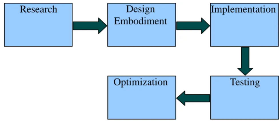
There are some procedure are develop in order to carry out this project. This is to ensure that the project flow is smooth and accomplish in the given period. Figure 3.1 below illustrates the milestones of the project.
Figure 3.1 The milestone of the project
3.1.1 Research
The first stage of conducting this project is to do research on vacuum robot matter. The research involve in this project are the study on the conventional vacuum robot, research on the specification for designing a vacuum robot, the study of autonomous robot and wavefront programming. A lot of research have been done to grasp the concept of the
Research Design
Embodiment
Testing Implementation
3.1.2 Design Embodiment
After getting the idea of the project, then the specifications defined to be considered in designing the robot. In this phase, designing the robot involves structuring of the body of the robot as well as the control circuitry to be integrated with the navigation system and vacuuming system. Along the line, developing the program is done as well as to make sure proper integration between both hardware and software. This will ensure the system will work effectively and efficiently as a whole.
3.1.3 Implementation
At implementation stage, the coding of SK40C board will be tested out to see if the I/O ports are functioning accordingly. Furthermore, the sensors and motors will be tested out individually to make sure they are in good condition. This is to test if all of them can interact well with each other and later, they are properly connect altogether to establish a complete system.
3.1.4 Testing
In this phase, the robot is tested out to see whether it work accordingly. The important criteria that could be tested are the navigating algorithms, the effectiveness of carrying out cleaning task, and the structure of the robot itself. The test results and information are collected to be used to further optimize the design.
3.1.5 Optimization
This is the last stage of the project where optimization is done to obtain the best form of the robot. At this stage, a lot of improvement can be done on navigating algorithms, the effectiveness of the robot to carry out its tasks, and also the structure modification. Also, more features can be considered to be add to the robot for it to be able to complete its tasks. Through optimization the robot's operations can be improve for it to be more effective and robust.
3.3 Tools And Equipment Required
There are several tools and equipment used. These tools and equipment can be group into two types which is software tools and hardware tools. Below discussed the tools and equipment used for this project:
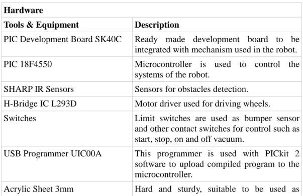
Table 3.1 List of Tools & Equipment Hardware
Tools & Equipment Description
PIC Development Board SK40C Ready made development board to be integrated with mechanism used in the robot. PIC 18F4550 Microcontroller is used to control the
systems of the robot.
SHARP IR Sensors Sensors for obstacles detection. H-Bridge IC L293D Motor driver used for driving wheels.
Switches Limit switches are used as bumper sensor and other contact switches for control such as start, stop, on and off vacuum.
USB Programmer UIC00A This programmer is used with PICkit 2 software to upload compiled program to the microcontroller.
platform layers inside the robot. Nickel Metal-Hydride Battery Rechargeable batteries, cheaper.
Vacuum Impeller + Motor To be used in vacuum system to provide vacuum compartment.
Wheels Track wheels, 50mm diameter x 30mm
width.
Twin-Motor Gearbox Motors used to drive wheels. Gear configuration is 203:1
Roller Roller ball is used to provide stable robot base.
Agitator Brush The brush attached to the vacuum inlet to capture dust and dirt.
Plastic Container Round plastic container to contain all the system of the robot as well as to provide good casing.
Sponges Used as insulators.
Brackets Used to hold elements of the robot such as motors, and sensors.
Software
Tools & Equipment Description
Microchip MPLAB v8.43 Software used to compile a program.
PICkit 2 v2.55 Used with UIC00A programmer to upload the compiled program into microcontroller. Microchip C18 compiler An add-in of MPLAB to compile C program
for PIC 18F type.
ExpressPCB and ExpressSCH To generate schematic drawing of circuits also to generate PCB layout of the schematic.
CHAPTER 4
EXPERIMENTAL WORK
4.1 Design Embodiment
4.1.1 Body Design
In order to design the body of the robot, some factor are being taken into consideration such as the overall size of the embodiment, the wheelbase, the size of each compartment inside the embodiment and the positioning of each elements inside the robot. The robot is designed to have 3 separate layers: (1) Base of the robot, (2) Vacuum apparatus, and (3) Circuits and battery. Further explanation on the diagram of each layers are as follows:
1. Base of the robot
The base of the robot consists of twin-gearbox motor, roller, vacuum inlet and wheels. The twin-gearbox motor is used because geared motor is more suitable to control the speed of motion and this geared motor can be configured to have high speed and low speed. Wheels are tracked and made of PVC so to have more grip on the surface while moving. Roller is placed on the front of this base to get a stable base. Vacuum inlet will have brush assembly attached to it to effectively capture dust and dirt. Shown below in Figure 4.1 is the base of the robot.
Figure 4.1 Base of the robot
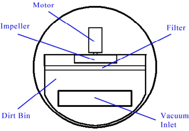
2. Vacuum apparatus layer
This middle layer of the robot comprises the vacuum inlet, dirt bin, filter, impeller and motor. The vacuum inlet on this layer connected to the base vacuum inlet through a pipe. This pipe allow the sucked dust and dirt to be collected inside the dirt bin. The filter is placed before the impeller to protect it from dust and dirt that are coming inside the dirt bin. The motor is used to rotate the impeller at high speed to create vacuum in the dirt bin. The diagram below shows the vacuum apparatus layer of the robot.
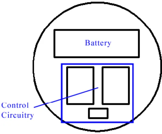
3. Circuits and battery layer
The top layer of the robot house the circuits and battery. The battery is placed at the front to get good weigh distribution after stacking the three layers together. Under the components of this layer, an insulator sheet is placed to avoid harm to the circuits. Figure 4.3 below is the diagram of this top layer:
4.1.2 Control Circuitry
The vacuum robot is composed of several components designed to meet the specifications defined. Control circuitry is important as to configure the systems of the robot to work properly. The control circuitry consists of the following circuits:
contact switches and IR sensors voltage regulator
motor and driver microcontroller
vacuum motor and relay
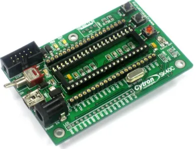
A PIC development board SK40C is purchased and PIC 18F4550 will be used as the brain of control circuitry for the robot. All the said circuits will be integrated with the PIC board to provide the control circuitry. Figure 4.4 below shows the circuit board of SK40C and the schematic of SK40C can be viewed in Appendix B: Schematic of SK40C.
4.1.2.1 Contact Switches and IR Sensors
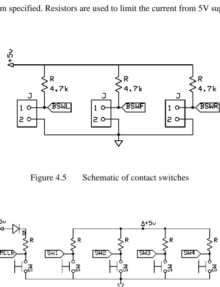
Figure 4.5 below shows the schematic of contact switch. Each of the switch signal (SWT1, SWT2, and SWT3) will be send to microcontroller for it to know which algorithm will be used based on the program specified. Resistors are used to limit the current from 5V supply.
Figure 4.5 Schematic of contact switches
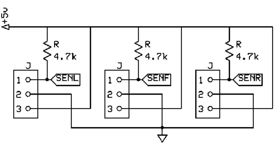
Another sensors used in this project is the SHARP IR sensors. The sensor has 3 pins: Vcc (yellow wire), Signal (red wire), and GND (black wire) as shown in Figure 4.7. Signal is fed into microcontroller for it to execute the specified program. This sensor's range of detection is 10cm to 80cm, thus, it is suitable to be used in distant obstacles detection. This component's distance characteristics can be viewed in Appendix D: GP2Y0A21YK Data Sheet.
Figure 4.7 SHARP IR sensor (GP2Y0A21YK)
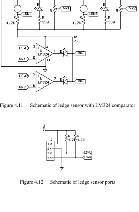
Figure 4.9 shows the ledge detectors circuit for the robot and Figure 4.10 is the IR Emitter-Receiver pair. This board has typical inputs such as Vcc, Signal, Gnd and requires a Vcc of +5V. The comparator LM324 is used to interface two IR sensors with LED indicators and MCU as shown in Figure 4.11 and 4.12. The sensing distance is approximately 1mm to 15mm and the sensitivity can be adjusted using variable resistors of 10K. The Green LED is used to indicate if the sensor detects surface. If the Green LED is off, then the sensor detects no surface, otherwise if the sensor sees surface, the Green LED lights up. This ledge detectors are positioned at the bottom of the robot in line with the wheels.
Figure 4.9 Ledge Detectors Circuit
Figure 4.11 Schematic of ledge sensor with LM324 comparator
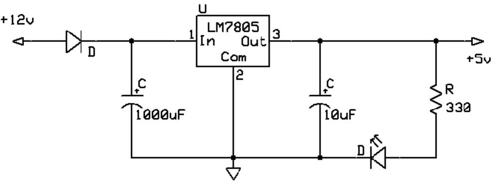
4.1.2.2 Voltage Regulator
Voltage regulator is used to regulate the 12V voltage supplied to step down to 5V voltage output. The reason to regulate the 12V is to provide 5V supply to components or circuits that are specified to operate at most 5V. This voltage regulator uses a voltage regulator IC which is 7805.
Figure 4.13 Voltage regulator diagram
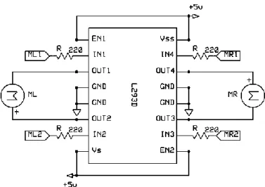
4.1.2.3 Motor and Driver
The circuit shown Figure 4.14 is used to drive two motors of the robot. This circuit uses L293D H-bridge IC to operate the two motors. The pin RA0, RA1, RA2, and RA3 are fed from the microcontroller. RA0 and RA1 are used to control motor B, while RA2 and RA3 to control motor A. When both inputs are low, the motor halts. When the first output is high and the second output is low, the motor will move forward. When first output is low and second output is high, the motor will reverse. If both inputs are high, the motor halts again.
Figure 4.14 Motor driver schematic
4.1.2.4 Vacuum Motor and Relay
To control the vacuum motor of the robot, a relay circuit is used. The relay schematics is as shown in Figure 4.16 have a 12V 5-pin relay which acts as a switch to power up the vacuum motor that runs on separate power supply. The variable resistor of 1Mohm is used to set the “sensitivity” of the circuit itself. When having the resistor turned to a lower value the relay switched on and off alternatively but when it is turned to the max value the relay is switched off completely. This is because of the presence of the two transistors NPN9013 that are always in saturation mode when supplied the voltage of 9V to the circuit. The vacuum motor is connected the the relay NO pin and GND.
Figure 4.15 Relay Circuit
4.1.2.5 Battery Monitor Circuit
The circuit shown in Figure 4.17 is used to monitor the voltage level of the battery in the vacuum robot. This circuit used the dot display IC as bar graph meter to indicate the charge level of 10V to 15V battery. It also used 10 LEDs to determine the charge level of the battery. Each LED represents 0.5 change in the charge condition of the battery. The battery is considered fully charged when the upper most LED is illuminated. When the lowest LED is the only left illuminated, this means that the battery has low charge and needs to be recharge.
4.1.2.6 Microcontroller
The circuit shown below is used to control all the mechanism of the robot. It is basically a 40 pins PIC 18F4550. The pins defined in previous figure that are to be connected to the microcontroller is labeled to correspond microcontroller pin. Port A and Port B are to be used as input lines while Port D are the output lines. Some more inputs and output of the microcontroller might be considered to be used in future at the optimization stage when more sensors and switches also the vacuum system to be added.
Figure 4.19 below illustrates the whole control circuitry being integrate together. The microcontroller (MCU), being the center of the control circuitry, connects the input circuits and the output circuits. IR sensors and contact switches are included into the input circuit while motors for both driving system and vacuum system are the output that will be controlled by MCU. Battery monitor circuit is considered as the input circuit since the result of this circuit (level of charge left in the battery) determines whether the robot should proceed its task or not. The full schematics of each circuits can be viewed in Appendix C: Schematics of Control Circuitry.
4.1.3 Sensors Alignment
When measuring the distance to objects in motion, proper alignment of the sensor is important so that objects can be detected and avoided. As discussed above, there are 3 different sensors used in this project which are ledge sensors, bumper sensors, and SHARP IR sensors. The figures below illustrate the position of each of the sensors on the robot:
Figure 4.21 Bumper sensors position
Figure 4.22 SHARP IR sensors position
Three different sensors have different position and function. The ledge sensors are placed below the robot, close to the surface floor, and before the motors. This is because the sensors need to detect the floor and ledge to avoid fall. While for the bumper sensors which are of the limit switches, all are place slightly above the ledge sensors and they are arranged so that
the sensors contact the obstacles first before the robot's body. The SHARP IR sensors are placed at the top layer of the robot and act as the main sensors. The arrangement of 90 degrees separation is to enable the robot to check for obstacles on the front, left, and right. If whenever these main sensors failed to detect obstacles, maybe due to low height of the obstacles, the other sensors can still play their role to detect, hence, they work together to avoid obstacles. Figures below are the diagrams of the robot with all sensors positioned:
4.2 Implementation And Testing
4.2.1 Navigating Algorithm
Random walk: the robot moves forward until it collides with an obstacle and if it runs into an obstacle, it will turn around to the opposite directions of the obstacle and moves forward.[4] This is actually called backtracking in random walk. There are other form of random walk but for this project, backtracking will not be used. Instead, whenever the robot detects an obstacle in front, it'll change its direction either toward its left or right. Random walk algorithm is chose to be implemented for this project since it is simple and less computation is done compare to other algorithms. This is important so as to keep microcontroller's memory handling in mind and not to exceed 70% of usage.
Below is the pseudocode of the algorithm used for this vacuum robot. For the full flow chart of this algorithm can be view in Appendix E: Random Walk Algorithm Flow Chart.
void roam_normal (void) {
initial_state(forward);
if(no_detection_in_all_sensors) {
forward();
last_act=0; // store this action if(battery_level=0)
break; // break roam_normal loop }
else if(left_IR_and_right_IR_detect_object) {
forward(); last_act=0; // store this
action }
else if(IRleft&&IRfront&&IRright) //all IR detect obstacles
{
reverse(); delay(3000);
last_action(); // check for previous action }
else if(IRleft&&IRfront&&!IRright) // two IR detect {
left_turn(); last_act=1;
}
else if(!IRleft&&IRfront&&IRright) // two IR detect {
right_turn(); last_act=2;
}
else if(!IRleft&&IRfront&&!IRright) // IRfront detects
{
reverse(); delay(3000);
last_action(); }
else if(!IRleft&&!IRfront&&IRright) // IRright detects
{
right_turn(); last_act=2;
}
else if(IRleft&&!IRfront&&!IRright) // Irleft detects {
left_turn(); last_act=1;
{ reverse(); right_turn(); } if(right_bumper||right_ledge) { reverse(); left_turn(); } }
Figure 4.25 Pseudocode of Navigating Algorithm
The algorithm above describes the reaction of the robot when encountering obstacles while it tries to complete its tasks. The obstacles are detected through numbers of sensors that are being placed onto the vacuum robot. Whenever the sensors detect an obstacle whether a wall, sofa, or staircases, the information is send to the MCU which then tells the driving motor to make a turn. For example, referring to the described algorithm above, whenever the front IR rangefinder sensor sense an object lie in the right side of the moving robot, the robot should make a slight left turn to avoid from running into the object. Even if the IR rangefinder sensors could not detect short object below the predefined detection level, bumper switch will then triggered if collision happened and the robot should find another path to walk. Sensors play a vital role as vacuum robot inputs on its environment especially in obstacles detection. This is to ensure the safety of the robot itself while performing its task effectively. Actual program can be viewed in Appendix F: Random Walk Full Program.
4.2.2 Parts Testing
Before actual implementation of the algorithm is done, it is important to check the condition of each of the I/O devices. Dummy programs are developed to test each sensors and driving motors. For sensor testings, LEDs are defined as the output indicators while having the sensors as the input devices. Total of eight sensors are being tested: 3 SHARP IR sensors, 2 Ledge Detectors, 3 Bumper Sensors.
void main(void) { init(); LED1=0; LED2=0; LED3=0; LED4=0; LED5=0; LED6=0; LED7=0; LED8=0; while(1) { if(!SENL) LED1=1;
else if(!SENF) LED2=1;
else if(!SENR) LED3=1;
else if(!BSWL) LED4=1;
else if(!BSWF) LED5=1;
else if(!BSWR) LED6=1;
else if(!LSWL) LED7=1;
else if(!LSWR) LED8=1;
} }
The program simply checks whether each of the sensors working or not. Initially, all LEDs are turned off. Whenever the sensors detect object, either IR sensors see a surface or limit switches of the bumper sensors contracted, the LEDs light on. The LEDs will turn off again if no object detected. Driving motors testing is using only dummy navigating program, without input from sensors. The purpose of this test is to check the condition of the motors, also the correct orientation before implementing the actual navigating algorithm. Having only the driving motors for the output, the input signals are defined in the program that is from the MCU itself. Figure 4.27 explains the code of dummy navigating program for driving motors testing.
void main(void) {
init(); LED1=0; LED2=0;
if(!SW1) { while(1) { forward(); pause(); reverse(); pause(); leftTurn(); pause(); rightTurn(); pause(); while(!SW1||!SW2); } } } void forward(void)
{ ML1=1; MR1=1; ML2=0; MR2=0; DelayMs(10000); } void reverse(void) { ML1=0; MR1=0; ML2=1; MR2=1; DelayMs(10000); } void pause(void) { ML1=0; MR1=0; ML2=0; MR2=0; DelayMs(5000); } void leftTurn(void) { ML1=0; MR1=0; ML2=1; MR2=1; DelayMs(2000); ML1=0; MR1=1; ML2=1; MR2=0; LED1=1; DelayMs(10000); } void rightTurn(void) { ML1=0; MR1=0;
DelayMs(2000); ML1=1; MR1=0; ML2=0; MR2=1; LED2=1; DelayMs(10000); }
Figure 4.27 Dummy Program for Motor Testing
The program starts when SW1 is triggered and it loops until either SW1 or SW2 triggered. The function blocks are used to define each of the robot's movement such as forward, reverse, pause, left turn, and right turn. Each of the movement are called and executed by delay function as to replace the input signals from sensors. By having pause in between each movement, the motor driver can be put to rest at 5 seconds.
4.2.3 Test Area
The purpose of testing the vacuum robot is to gather data in order to know the average time cleaning in a 1.5 square meter floor area. An uninterrupted power supply is used to supply the robot during testing and talcum powder is used as dirt to be cleaned. The timing of the robot start eventually when the power is turned on. The unit is let to run around the 1.5 square meter area until it approximately covers 90% of the area. The robot can be directed to the position of the assumed home base and then it will head to the location. The battery life of the vacuum robot is only for 45 minutes and 30 minutes scheme is set so that the remaining 15 minutes is used to locate the home base.
The 90% approximation that is cleaned by the robot is done through comparison with a 0.3 square meter floor. The lines of which the robot transverse are observed until it navigated almost everywhere around the area. If there are still small areas are left unclean, it is approximated by combining these and if it would be less than 10%, it can be concluded that the vacuum robot had cleaned 90% of the floor and time of running is recorded. Figure 4.28 illustrate the test area and it's dimension.
CHAPTER 5
RESULTS AND ANALYSIS
5.1 Results And Analysis
Generally, all the circuits have worked according to their design but there are some minor problems. The ledge sensors have small inconsistent sensitivity problem. The output values vary depending on the floor color. It is needed to calibrate the ledge sensors according to the floor color. Another problem is from the IR sensors, both the ledge sensors and the SHARP IR sensors are affected by direct sunlight. There was also a minor problem with the twin-geared motors. At first, the gear ratio was set to 58:1 with torque size of 150g/cm and was not able to drive the whole system for a long time because of the weight of the system. It was realized that the gear ratios need to be changed to a much higher torque size configuration to drive the system. It is now changed to 203:1 with 430g/cm of torque.
It is found that there is one major drawback of this vacuum robot which is the battery life span. The battery has a very short battery life span which only lasted 15 minutes. It is decided then, for the robot to run longer, another set of battery is used to supply the power to the motors in parallel. This is due to the power supply cannot be shared with the control circuitry that could result insufficient power to the sensors. Although this made the robot able to run much longer time, the time is not yet enough for it to cover a whole area. Thus, home base returning for recharge algorithm is inserted into the program.
After design finalization, the current consumptions of both driving motors and vacuum motor are measured. The results is shown in Table 5.1 below:
Table 5.1 Current Consumption
Motor System Current (A)
Twin Geared Motor (203:1) 2.1
Vacuum motor 4.5
Circuit with Twin Geared Motor 0.75
Total Current Consumed 7.35
Table 5.2 shows the results of three full circuit testings. The tests conducted many times but only three optimal time are gathered to have minimal time differences. The average time is calculated as well.
Table 5.2 Time Measured for The Prototype Testing
Tries Recorded Time (minutes)
1 35
2 40
3 38
Average Time (minutes) 37
The calculated average of the time for the five tries is 37 minutes. This means that the vacuum robot can cover approximately 90% of the 1.5 square meters at 37 minutes average. The maximum time the battery can last is 45 minutes, thus, the remaining 8 minutes ample time for the robot to find its way back to the home base for recharging.
CHAPTER 6
CONCLUSION AND RECOMMENDATION
6.1 Conclusion
The autonomous vacuum robot, needed to take into account several considerations in order for it to navigate and vacuum an area. The vacuum robot is specified to be able to detect obstacle and avoid it as to achieve effective cleaning task. The important input of the robot are the sensors and motors are the output components. Information from the sensors are sent to the control board, SK40C, which then will tell the motors to react accordingly. Random walk algorithm is implemented as the navigating algorithm for this project.
Autonomous Electric Vacuum Robot can help make the life for people more meaningful. Vacuum robot is use to clean a room with less supervision of its user. With this in mind, users can replace their chores such as vacuuming with something that has more importance to them. The Autonomous Electric Vacuum Robot is aimed to be simple, affordable and effective for users.
6.2 Recommendation
Although the objectives are met, the project can still be improved. One part is the sensors. The IR sensors used in the vacuum robot can be problematic discussed earlier. The effectiveness of the ledge sensors, especially, are dependent on the color of the floor as the sensors have difficulty in differentiating the dark color of floor from that of a ledge. The IR sensors are also affected by direct sunlight which partly explain the sensitivity issue of these sensors. Therefore, it is recommended to use ultrasonic sensors instead of IR sensors.
Another part that could be improved is the battery system. The design can be perfected if additional circuit that can autorecharge the battery is added into the vacuum robot. This can be used to compensate the battery life span of the robot and so to have more time cleaning for larger area to cover. It is also recommended to have timed tasks be set in the algorithm, for example, to have the robot timed its recharging time.
REFERENCES
[1] (2009). Autonomous Floor-Cleaning Robot. United States Patent. Retrieved from http://www.freepatentsonline.com/
[2] (1998). Coordination of Behaviours for Mobile Robot Floor Cleaning. Jntl. Conference on Intelligent Robots and Systems. Retrieved from IEEE Xplore
[3] (1994 ). Path Planning And Guidance Techniques For An Autonomous Mobile Cleaning Robot. Christian Hofner and Gunther Schmidt. Retrieved from IEEE Xplore
[4] (2002). Development of Small Robot for Home Floor Cleaning. Yong-Joo Oh and Yoshio Watanabe. Retrieved from IEEE Xplore
[5] (2008). Autonomous Robot Vacuum Cleaner. United States Patent Application Publication. Retrieved from
http://www.freepatentsonline.com/
[6] (2009). Omni-directional robot cleaner. United States Patent Application Publication. Retrieved from
http://www.freepatentsonline.com/7568536.html
[7] (2008). Robotic Vacuum Cleaner. United States Patent Application Publication. Retrieved from http://www.freepatentsonline.com/
[9] Random Walk Application for Autonomous Vacuum Cleaner Robot. E.
Maningat, B. Monterola, E.Obrero, R.Samante, J. Villafuerte
[10] (1998). Coordination of Behaviors for Mobile Robot Floor Cleaning. Sherman Y. T. Lang and Bing-Yung Chee. Retrieved from IEEE Xplore