INDUSTRIALES Y DE TELECOMUNICACIÓN
Titulación:
INGENIERÍA DE TELECOMUNICACIÓN.
Título del proyecto:
CHARACTERIZATION AND USE OF THE PAC7001 CAMERA
WITH THE POSIT ALGORITHM ON AN AVR
MICROCONTROLLER.
Ángel González García Luis Javier Serrano Arriezu Pamplona, septiembre 2013
I conrm that this paper is entirely my own work. All sources and quotations have been fully acknowledged in the appropriate places with adequate footnotes and citations. Quotations have been properly acknowledged and marked with appropriate punctuation. The works consulted are listed in the bibliography. This paper has not been submitted to another examination panel in the same or a similar form, and has not been published. I declare that the present paper is identical to the version uploaded.
Vienna, 29th of September 2013
Este proyecto trata sobre la caracterización y uso de la camara PAC7001 para la implementación de un sistema de estimación de pose. Este sistema estará orientado al uso en tecnologías asistivas como un sistema de posicionamiento de la cabeza. La pose se calcula mediante el algoritmo POSIT, ejecutado en un microcontrolador AVR. Este algoritmo a su vez será optimizado para su uso en disposivos AVR de 8 bits.
En este proyecto las capacidades de la camara son analizadas, comprobando las diferentes conguraciones tanto de hardware como de software. Para probar las diferentes conguraciones se montará un prototipo del sistema, y se analizará la respuesta del mismo para las diferentes conguraciones.
Además del software del microcontrolador, se implementan diferentes programas auxiliares para analizar el sistema desde el PC , de forma que se facilite el desarrollo del mismo en un futuro.
Diese These beschreibt die Charakterisierung und Verwendung des Kamerachips PAC7001 zur Positionsbestimmung im Raum mittels Infrarot Referenzsignalen.
Die Position wird per POSIT Algorithmus bestimmt, welcher auf einem AVR Microcontroller ausgeführt wird und für diesen optimiert wurde.
Es wird sowohl die Eignung der Kamera an sich analysiert, als auch ein einfaches Head-Tracking system aufgebaut welches als Maus-Ersatz benützt werden kann.
This thesis focus in the characterization and use of the PAC7001 camera in order to implement pose estimation system. This system would be used in assistive technologies as a head tracking system. The pose is calculated with a POSIT algorithm running in an AVR microcontroller, the algorithm is improved to work on AVR 8-bits devices.
In this thesis the possibilities of this camera are analysed, by both hardware and software conguration. Therefore a initial head tracking system is implemented. Along with the microcon-troller software, debug programs for the PC are implemented in order to help in future development.
1. Introduction 1
1.1. Objetives . . . 1
1.2. State of the Art . . . 1
1.3. Methods, concepts and devices . . . 12
2. Development 20 2.1. Hardware research and design . . . 20
2.2. Software design . . . 22
2.2.1. Software overview . . . 24
2.2.2. Data format and structures . . . 25
2.2.3. Actual block diagram . . . 28
2.3. System operating range . . . 36
2.4. Tests . . . 38
2.5. Support programs . . . 51
2.6. Future improvements . . . 55
2.7. Summary and conclusions . . . 56
Bibliography 58 List of Figures 62 List of Tables 63 List of Abbreviations 64 A. Provided Files 65 B. Hardware schematic 66
1.1. Objetives
The focus of this project is the characterization and analysis of the PAC7001 camera, in order to implement a head tracking system, using the POSIT algorithm in an AVR microcontroller.
The rst goal is to reverse engineer the PAC7001 camera. This camera came, at rst, with a very simple and incomplete datasheet, so the understanding of the camera, and its registers, is the rst step in the project.
The second step is to implement the POSIT algorithm in an 8-bits AVR microcontroller. One of the challenges when implementing the algorithm in this microcontroller, is the lack of oating point operations, which are necessary in the POSIT algorithm. This oating point operations are programmed in the AVR, which makes them slow.
Finally with the camera and the POSIT algorithm implemented, the goal is to check if it is possible, with these devices , the development of a head tracking system.
1.2. State of the Art
Nowadays, there are several devices, adapted to be used by disable people, which make them less dependant. Some of the devices improves mobility (i.e: wheel chairs or walkers), others replace parts of the body, the prosthesis, or help with dierent disabilities. Due to the wide range of existing systems, it is impossible to explain all of them, so we are focusing on the interface human-computer, where a computer can be a PC, a laptop or a smarthphone.
The interfaces human-computer can be unidirectional or bidirectional. The interest in this Master Thesis is about unidirectional systems, more specically the input devices adapted to disabled people, so a enumeration and description of them is made in the next paragraphs. The systems that we are talking about can be grouped in:
• Physical Switches • Mouse interfaces • Image recognition • Voice Input
Physical Switches
The simplest of this kind consists in a single push button, which has been enlarged so it is easier to hit. These devices need less force to be activated and deal better with bouncing. These push buttons are limited by the fact that they can only have two states, activated or deactivated, so the usefulness is limited. That is why these kind of inputs are more used by people with severe disabilities, as they can not use a more complex system. To increase the utility, arrays of buttons
are used. They are usually arrays of special push buttons (the ones just commented) with bold colors to be easily distinguishable. We can nd a lot of examples of this kind of buttons:
• Gumball Switches1 • Big Buddy2 • Switch it up3 • It switch 4
Figure 1.1.: Example of big push buttons.[1]
These arrays of buttons can be designed for a specialized purpose or to work as a keyboard. To keep all the keys in the keyboard the quantity of needed buttons make impossible to make them big, so other solutions are followed. The keyboard layout is changed to be used by only one hand or with low mobility in the ngers. The main problem is that the keys keep the same size or even smaller. Some examples can be found:
• Keyboard BigKeys ABC layout5: In this product, the size of the keys has been increased,
improving visibility and accuracy while typing.
• Contoured Advantage6: This is an example of how the position of the keys are changed to
adapt to low mobility and to be more ergonomic.
• BAT Keyboard7: The last one is a single hand controlled keyboard. The dierent key
combinations give us all the possible characters of a keyboard.
1http://enablingdevices.com/catalog/capability_switches/best-sellers/ gumball-switches-accessories 2http://www.spectronicsinoz.com/product/big-buddy 3http://www.adaptivetechsolutions.com/pd-switch-it-up-switch.cfm 4http://www.infogrip.com/products/it-switch.html 5http://www.iltsource.com/BigKeys_Plus_Color_ABC_p/bigkeysmp6.htm 6http://www.infogrip.com/products/keyboards/contoured-advantage.html 7http://www.infogrip.com/products/keyboards/bat-keyboard.html
Figure 1.2.: Keyboards adapted to dierent diseases[2][3]
In some cases more sophisticated systems are needed. The sip-and-pu systems, are switches in which each action, sip and pu, has a dierent function. The function depends on the application and it is specically design for each case. However, the research in this devices makes it possible to increase the number of functions, with the distinction between soft and hard sip and pu. These switches are used when severe mobility diseases are present, since no movement is necessary to activate it. They are activated with the mouth, so they can be mounted on the head, on a table or on a wheel chair. From this devices we can nd:
• SB-4H Sip and Pu switch with hardware 8 • Sip and Pu with headset9
Figure 1.3.: Two implementations of the sip and pu systems.[4][5] Mouse interfaces
Simple machines can be used with a few buttons, however most of the devices we use, such as smartphones or PCs, require a pointer controller. The usual interfaces are mouse and digitizer, however these interfaces are not suitable for some disabilities. In this scenario dierent approaches have been followed.
In hardware the simplest way to implement a mouse interface is by a joystick, the move of the joystick in each axis moves the pointer in that axis. The adapted joystick usually consists in one or two switches and a bigger than usual handle. Depending on the disability the joystick is going
8http://www.zygo-usa.com/usa/index.php?page=shop.product_details&flypage=vmj_naru.
tpl&product_id=314&category_id=139&option=com_virtuemart&Itemid=11
to cover, it may change its behaviour: resistance to movement, total displacement of the handle or available axes. We can see some examples of this kind of mice in gure 1.4, and a list of commercialized adapted mice:
• Funkey Joystick10
• OPTIMAX Wireless Joystick11
Figure 1.4.: Dierent implementations of joysticks, working as mice.[6][3]
When the disability prevents moving the joystick, the pointer can be moved using buttons (gure 1.6) or trackballs. The layout of the buttons in the rst solution varies among products. In some of them there are only four buttons, two for each axis, but more complex systems can include combinations of the basic axis, implementing i.e.: diagonal movement in some keys. The trackball alternative consists of a ball in which the pointer moves according to the amount and direction of the rotation. The advantages of the trackball over the buttons and joysticks is the freedom of movement of the pointer. However, it is more dicult to use than the others.
• Mouse button box12
• Footime Foot Mouse with Programmable Pedal13
Figure 1.5.: Trackball systems with dierent buttons layout.[7]
10http://www.keytools.co.uk/funkey-joystick.html
11http://www.infogrip.com/products/mice/optimax-wireless-joystick.html 12http://www.enablemart.com/mouse-button-box
Figure 1.6.: Mouse buttons system, activated with the feet.[7]
In the case of not so severe disabilities special mice can be used. These mice may be bigger, have less buttons or dierent sensibility than ordinary mice. Sometimes the mouse has the buttons moved apart and they have to be activated by the other hand, this is used when the disability prevents movement of ngers.
In some cases touch screens can also be used. These interfaces do not require force to be applied but work only with skin contact. The size, resolution and behaviour to touches vary among dierent models and uses, increasing the utility of these interfaces. They can be used as switch buttons, mouse or even both at the same time. The implementation of movement patterns increases the versatility of this input systems. They can be controlled by the ngers, the whole hand or with a stick. And they can be prepared to avoid unintentional pushes. Some examples of track pads are:
• Orbitrack14 • Track-IT15
Figure 1.7.: Two trackpad system.[8][6]
14http://www.pretorianuk.com/orbitrack 15http://www.keytools.co.uk/trackit.html
Image Recognition
When the previous systems are not enough, image recognition can be used, which consists in the recognition of patterns or shapes (i.e.: Head, eyes and body) in images recorded by a camera. The method used by the cameras varies among systems: some cameras work with visible light (regular cameras), on the other hand the IR cameras, which usually have IR light sources, see the rebound of the IR light. The complexity of this method lies in the recognition algorithm. In all three cases (Head, eyes and body), the shape, size and layout vary among individuals, which makes the recognition of all possible shapes, sizes and layouts very complex. Since few years ago this kind of input can be seen in commercial products, the most important is the Kinect for Xbox16 but due
to its complexity it will be reviewed later.
One of the rst image recognition system researched tracked the gaze. It was one of the rst implemented methods because of the low variance in the algorithm for dierent eyes, that is, the algorithm has to distinguish a circle (the pupil) and the cornea, which are almost the same for every eye. To do this, the camera has to record images from the eye. In these images the software recognizes the pupil and the rest of the eye. With the position of the pupil relative to the rest of the eye, the software is capable of calculating the gaze orientation and translate it in a movement of the pointer on the computer. To make it easier, the camera which detects the eye, is usually head mounted and positioned just over an eye, so even when the head is moved, the eye keeps in the same position relative to the camera. The eye tracking can be used to move the pointer in a screen or to use simple machines. One of its disadvantages is the losing of the view, of what one is doing, because the eyes are moved. The utility of these systems are scenarios in which the important event takes place where you are looking at (like moving the pointer, the important thing is where the pointer is). In addition, implementation of patterns is hard because it is not easy to do movements with the eyes for a long time.
Figure 1.8.: Eye tracking, pupil's features[9]
As the eye tracking was the rst developed system, there are eye tracking systems for dierent purposes, from psychology studies to marketing and human-computer interaction research. In gure 1.9 the Tobii X2-69 Eye Tracker 17 can be seen, which is a small implementation of an
eye tracking system, this device can record the position of the eyes so they can be later analyzed, for example, to study how people look at the websites or pictures. This device has the added complexity that the camera is not near the eyes so the algorithm has to recognize the face and the eyes, and then calculate the position and orientation of them. Another eye tracking system is
16http://www.xbox.com/es-ES/Kinect/GetStarted
17http://www.tobii.com/en/eye-tracking-research/global/products/hardware/
the Eye tracker type L18. This one is mounted near the eye so the implementation is easier than
in the rst one. Although two examples are given, many others exist, but there are not so many dierences among them. Other examples that can be found are:
• S2 Eye Tracker19 • EMR-920
• RED25021
Figure 1.9.: Examples of eye tracking system already developed.[10][11] [11]
Due to the loss of vision while working and the impossibility to do complex moves with the eyes, head tracking was researched. Head tracking works in the same way as eye tracking, but in this case the position and orientation of the head are tracked. The procedure is also the same: the camera records the images and then the software has to recognize the head to calculate its position and orientation. With the eye tracking, only the orientation of the eyes can be used as an input parameter. However, with the head tracking the position and the orientation can be used, which gives more possible inputs. This system has its advantages, but this requires a more complex algorithm for detection. The face of dierent people varies more than their eyes, and the head has to be distinguishable from the environment which also varies, from dark rooms to the most illuminated oce. In some cases, the background of the image may be the same tone as the face which also complicates the head recognition. In most of the cases the recognition is not for the head but for the face. Once the position and orientation of the face is calculated, the same values are for the head. We can see in gure 1.10 how the algorithm detects the face and calculate the position and orientation of it.
The head/face tracking products that are commercialized are harder to nd, this is because they are more complex than eye tracking. The FaceLABTM522 is a device capable of doing eye
and head tracking. It can track the head movement in all the axis and rotation in the x and y axes. This device not only can acts as an input for the pointer, but also as a study device. It can create heat maps (example of heat map of a website gure 1.12) so one can study where people spend more time starring.
18http://en.pertech.fr/eye-tracker-l.html 19http://mirametrix.com/products/eye-tracker/
20http://www.nacinc.com/products/Eye-Tracking-Products/EMR-9/
21http://www.smivision.com/en/gaze-and-eye-tracking-systems/products/red-red250-red-500.html 22http://www.seeingmachines.com/product/facelab/specifications/
Figure 1.10.: Example of head tracking methods and results.
Figure 1.11.: FaceLABTM5[12]
Figure 1.12.: Heat map generated by a eye tracking system, which colour the webpage indicating where the user stay more time looking at.[13]
The last step in image recognition is the body recognition. Although, this kind of recognition is not very useful in people with disabilities, it is worth mentioning. This is the most complex system of image recognition since it has to distinguish between the body and the environment. The main problem is that the body may not be looking forward to the camera, but turned so the camera can not see an arm or leg. The dierent types of bodies and clothes makes the task more dicult. The most successful device capable of body tracking is the already mentioned Kinect for Xbox. In gure 1.13 can be seen that the device has[14]: color and depth-sense lenses ,voice microphone array and a motor for tilt adjustment of the sensor. According to [14] it can track up to 6 people and 20 joints per active user. The device is also capable of speech, face and gesture recognition.
Figure 1.13.: Kinect system for Xbox.[15] Speech recognition
The speech recognition (SR) consists in the translation of spoken words into text or orders that can be understood by a computer or a device. Some SR systems are trained, requiring the user to read a text. Then, the SR learns to recognize the voice. Other systems are speaker independent, meaning training is not necessary. If the SR needs to be trained it should be used only by one person, which makes the implementation easier and the recognition more accurate. The speaker independent, on the other hand, is harder to implement and the recognition less accurate. For disabled people the speaker dependent SR is more suitable, as it is used only by one person.
The SR does not require physical movement of the user, so can be used with severe movement impairment. This fact makes it useful in various situations: it can be used when severe mobility disabilities are present, or to increase the comfort when using devices. The main disadvantage of this kind of input systems appears when moving the pointer. When specic orders are necessary (such as open, close, move,..) the SR systems are useful. However, moving the pointer can be hard.
There are dierent options in SR: there are SR engines, so developers can use them to do their own programs, fully functional programs, which the user only have to install, and integrated solutions, in which the SR is integrated in the operating system. The rst group, the engines, is suitable for specic situations in which is hard to nd software that fulll the requirements. These scenarios, which require special conditions, need to be implemented by SR engines. We can nd some example of these engines:
• CMU Sphinx23: This is an open source toolkit for speech recognition.
• Julius24: It can be used under BSD license but need of citation. • RWTH ASR25: Proprietary speech recognition toolkit.
• Zanzibar OpenIVR26: It uses the CMU Sphinx ASR engine and can also work with TTS(Text
to speech)
The general purpose programs are already programmed and usually cover the basics functional-ities. Due to the existence of dierent operating systems, there are programs for the most popular ones. Some examples are:
• LumenVox27: for Linux and Windows, it can understand 6 languages. • Dragon Naturally Speaking28: Made by Nuance, is the Windows version.
• Dragon Dictate29: The same company of Dragon Naturally Speaking made this one for
MAC users
• Dragon Dictation30: This is the iPhone and iPad version from Nuance software. • Vocapia31: Is a completely functional software for Unix systems.
Even these fully operational programs are used, most of the main operating systems have their own SR system integrated in them. Usually the integrated SR only covers the basics requirements for elementary use. Nowadays Windows, MAC OS and android implement a speech recognition software, so the use of more complex SR system is only in cases with special requirements. IR Tracking
The IR tracking systems usually consist of an IR light source, an IR camera and in some cases reective stickers. The camera registers the IR light from the light sources, or the stickers, and calculates the position and the orientation of the object to be tracked. The layout of the devices varies between implementations, in some cases the lights or the stickers are in the tracked object. In other cases, the camera is mounted on the tracked object.
The implementation of the lights on the tracked objects is used in many scenarios. In the audiovisual industry, for complex special eects, the body of the actor is covered by IR light sources and, with several cameras, the body is tracked and can be easily modied in post-production, i.e.: modifying the shape or the texture of the skin. In high-level sport training, it is usually used to track the movement of the sportsman, so it can be analyzed in slow motion and therefore improved. For 3D face model animation these kinds of systems are used, a human model has reective stickers on his face. These stickers are tracked and then passed to the 3D face model so it moves as the human model. The scenarios use a complex layout of lights and cameras so they are not suitable for home implementation. There are simpler layouts suitable for use at homes, which consist in a camera and a few small light sources. Some implementations are:
24http://julius.sourceforge.jp/en_index.php?q=en/index.html 25http://www-i6.informatik.rwth-aachen.de/rwth-asr/ 26http://www.spokentech.org/index.html 27http://www.lumenvox.com/products/speech_engine/ 28http://www.nuance.com/dragon/index.htm 29http://www.nuance.com/dragon/whats-new-dragon-dictate/index.htm 30http://www.nuance.com/for-business/by-product/dragon-dictation-iphone/ 31http://www.vocapia.com/
• TrackIR 532: this is a commercial head tracking which works with IR lights. It consists of an
IR camera, and a set of lights which have to be mounted on the head (they can be attached to a hat, or to a headset).
• Johnny Chung Lee33 developed a head tracking system with the Wiimote camera and the
LED bar mounted on the head, can track the position and modify the images on the screen according to the head position.
On the other hand, the other implementation mounts the camera on the head and the lights are xed. The system knows the layout of the lights, and has to calculate the position of the camera based on what the camera detects. This system is used by the Wiimote; the element that is moved is the camera and the lights are always xed in top of the screen. This project follows this implementation, the camera will be mounted on the head, while the lights will be on the screen.
Pose estimation method
With the image of the lights taken by the camera, it is necessary to estimate the pose, translation and rotation of the camera. In order to do that several algorithms exist, however only the most important ones are commented.
• CamPoseCalib (CPC) • POSIT algorithm.
• Direct Linear Transform (DLT)
The CPC is the algorithm implemented in the BIAS library34. This algorithm is based in the
non-linear least squares problem, in which it is necessary to minimize a function error:
ˆ φ= arg min φ m X i=1 (ri(φ))2
In Gauss-Newton method, the term ri(φ) represents the rst order derivative of the residual.
The algorithm is used to estimate the rotation and translation of an object. It needs the initial pose and then it is able to calculate the new pose. The goal of this method is to nd the new pose by looking for the minimum of the error function. This minimum is found by calculating the derivative of the residuals. Once the minimum is found, the new pose is taken as correct.
To use this method, the functions for the derivatives are directly set, that is, the steps that the algorithm takes are predened and may not be correct for some situations. In some cases the Gauss-Newton method is interpolated with the gradient descend. This makes the algorithm more robust, since it can start far o the correct minimum and still nd the pose.
The POSIT algorithm uses a scaled orthographic projection (SOP), which gives a wrong per-spective projection. However, when the algorithm converges, the true perper-spective is calculated. The SOP approximation leads to a linear equation system for the rotation and translation. This method uses a scale value for the points, and it is updated in every iteration.
32http://www.naturalpoint.com/trackir/products/trackir5/ 33http://johnnylee.net/projects/wii/
This algorithm iterates by calculating the value of the scale value for the dierent points, until the change of the values between two consecutive iterations converges to 0. When that occurs the algorithm converges, and the solution is the translation and rotation vectors obtained by the algorithm. The advantage of this algorithm is that it does not require a starting pose, as in CPC. However, when the object is planar, the POSIT algorithm fails because dierent poses have the same orthographic projection. In that case the POSIT for coplanar points is used. This algorithm creates two poses for the object, two I and two J. At the end of the algorithm, it selects one of them according to the distance between the points and a threshold level.
The DLT estimates the parameters of the projection matrix. To estimate all 12 parameters in the matrix, at least 6 points are needed. This method is the simplest one, however it is much slower than the CPC or the POSIT.
In our project the POSIT algorithm will be used, since it is the fastest one and it does not need the rst pose to calculate the next one. That means that the POSIT can calculate the pose from one image.
1.3. Methods, concepts and devices
In this section the devices and algorithms used in the project will be explained. For the hardware part the next devices can be found:
• PAC7001CS: This is an IR camera which also implements object tracking algorithm. This
implies that the camera does the job of analysing the image and get the coordinates of the objects in the image.
• AT90USB1286: This is the microcontroller with AVR architecture, it works at 16 MHz at
5V.
• LED structure: A structure holding the regular IR LEDs.
In the software part, the algorithm used by our application to calculate the position of the camera relative to the lights, is called POSIT. The communication between the camera and the microcontroller is over UART and the microcontroller uses USB to send the pointer data to the computer or device.
PAC7001CS
The PAC7001CS is the IR camera used for the project. This camera has the IR sensor with the DSP processor implemented. Therefore, the coordinates and size, of the object that are tracked, are sent instead of the IR image that the camera receives. Some features of the camera are:
• Electronic features:
Tracks up to 4 object
The supply voltage range is from 3V to 5V, but the data must me 3.3V The communication interface is UART at maximum of 1687500 baud System clock of 27MHz (oscillator included in the package)
Maximum current consumption 60 mA Frame rate from 10 to 200 fps.
• Camera features
Focal length: 1.3mm Pixel size: 11µm×11µm Sensor size: 0.3 cm = 1/10
The camera has two operational mode: Initial mode and Operation mode. In initial mode the camera does not track objects or send data trough the UART, but wait for the master to send the registers conguration. In this mode the camera accepts four orders:
• Check device (0xEA): This command is used to check the connectivity and functionality of
the camera. Once the camera receive 0xEA it answers with Tracking V01 string. The rst time the camera is powered on, this command must be sent in order to activate it. If the string is received, the connection is correct and the camera can start sending and receiving data.
• Set register (0x10): The set register command should be followed by two or three another
bytes. The rst byte after the 0x10 is the register number one wants to change and the following one or two are the new value for that register. The number of bytes depends on the register to be changed, some registers need only one byte while other ones require two. Once the register is changed the camera will answer with a 0x10 byte.
• Read register (0x11): This byte must be followed by the number of the register which on
wants to be read.
• Switch to Operation Mode (0x8D): With this instruction the camera switches to
Opera-tion Mode.
While in Initial mode the register can be set, these registers change some parameters of the camera. There are several register which can be congured, however the most important ones for our project are explained.
Name of byte Name Function
0x00 Gain 1 Sensor analog gain 0x01 Gain 2 Sensor analog gain
0x02 Sensor update ag It has to be changed to 1 to update the reg-isters once are changed.
0x05 IW (2 bytes) Image Width 0x06 IH (2 bytes) Image Heigh 0x0F Feature option
en-able ag Which features of the tracked object wantedto be included in the data while in Operation mode.
0x11 Baud rate Change the baud rate of the UART commu-nication
Table 1.1.: Some register of the camera.
Once the camera has been congured by the master, it can be turned to Operation mode. In this mode the camera does not accept more conguration orders, it just send the object's features
set in the Feature option enable ag register. The structure of the data received during Operation mode can be seen in table 1.2. The data received is structured in Frames, every frame has the data of four objects. The frame starts with the frame header, then the features of the objects come four times.
The communication between the camera and the microcontroller is through the UART port. The baud rate of the communication is set in the register 0x11, as can be seen in table 1.1, the possible values for the baud rate go from 19200 Bd to around 17 MBd. The UART transmission must be congured to start with a start bit, followed by 8 bits of data, and the stop bit. The number of objects that the camera tracks, depends on which is the UART baud rate. With the default baud rate the camera only sends data of one object, while with 115200 Bd, the camera can send the data of up to four objects.
Byte name Bit Function
Header 0xFF 0x00 0xFF 0xFF Frame header to distinguish between frames Flag Byte
Bit 7: Always 1
Bits [5:6]: 01 when trace is OK
Bits[0:4]: Frame number
Used to check if the object has been tracked or not.
Object Flag Byte
Bit 7: Always 0 Bits[4:6] : Reserved Bits[2:3]: 00 Circle 01 Bar 10 Circle-hole 11 Bar-hole Bit 1: Reserved Bit 0: 0 if nished
It is used to check which kind of object is the camera tracking.
X coordinate First goes the High byte,
then the Low byte Gives the X coordinate of the center of thetracked object. Y coordinate First goes the High byte,
then the Low byte Gives de Y coordinate of the center of thetracked object. Size First goes the High byte,
then the Low byte Gives the size of the tracked object. EOB Bit 7: Always 0Bits[4:6]: Object number
Bits[0:3]: Checksum Distinguish between objects Table 1.2.: Structure of the data received from the camera. AT90USB1286
The AT90USB1286 is a AVR 8-Bit Microcontroller, which is mounted in a USB based microcon-troller development board called Teensy 2++35. The features of the AT90USB1286 that are more
important for this project can be found in table 1.3. The maximum frequency depends on the supply voltage, for 5.5V is 16Mhz and for 2.7V is 8Mhz.
The rest of the characteristics can be found in the datasheet, and they will be not commented due to its extension.
Figure 1.14.: Image of the Teensy2++[16]
Feature Value
Supply voltage 2.7 - 5.5V Maximum frequency 8 - 16Mhz In-System Reprogrammable
Flash program memory 128 KB EEPROM Data Memory 4KB
Internal SRAM 8KB
USB Full Speed 2.0 (Device)
UART Channels 1
Table 1.3.: Some register of the camera.
POSIT Algorithm
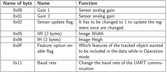
The POSIT algorithm(Pose from Orthography and Scaling with Iterations) is an algorithm used to estimate the 3D pose from a 2D camera. The POSIT requires to detect feature points in the image, and to know the real shape of these points in 3D. With this data the algorithm can calculate the position of the camera/object in 3D space.
It is needed to select one of the feature points of our model as reference point. From there, the algorithm with the vectors from this reference point to the other feature points, will do the calculation of the rotation and translation vector of the object.
In gure 1.15 we can see how the 3D coordinate of an object (M0-Mi) project in the camera
plane (m0-mi). The Pi and pi points are the scaled orthographic projection of the point Mi. f
is the focal length of the camera and Z0 is the distance between the camera and the reference
point in our 3D model.
From [17] can be seen that the equations that are need to be solved are:
M0Mi·I = xi(1 +i)−x0 (1.1) M0Mi·J = yi(1 +i)−y0 (1.2) I = f Z0 i (1.3) J = f Z0 j (1.4) i = 1 Z0 M0Mi·k (1.5)
Figure 1.15.: Points in real world and their projection in the image plane[17]
When values are given toi the equation system become a linear system in which onlyIandJ
are unknowns. OnceIandJare found, we can calculateiandjby normalization. This part of the
algorithm is the called POS( Pose from Orthography and Scaling). The orthography projection pointpi depends on the value ofεi, so given anεwhich is not exact to the actual value gives us
only approximations to the pose. But once the I and J vectors have been calculated, improved
values ofi can be computed and used in the next iteration to get better approximations to the
pose. This last part is called POSIT( POS with iterations).
For the implementation two matrices are necessary: The A and B matrix. The A matrix is a matrix with the vectors of the points relative to the reference point in 3D space, and the B matrix is the pseudoinverse matrix of the A matrix. The shape of our real 3D shape will be xed so the B matrix can be computed before so the microcontroller does not have to calculate it every time the program is executed. With this two matrices the algorithm is:
• Step 1: Setεi = 0for every feature point in the object, so the POS algorithm can be used. • Step 2: compute i,jandZ0
Compute the image vectorsx0 andy0 coordinates. Each coordinate is calculated as: x0i = xi(1 +εi)−x0 (1.6) y0i = yi(1 +εi)−y0 (1.7)
With the image vector theI andJcan be obtained by multiplying them,I=Bx0 and J=By0.
Compute the scale of the projection for each coordinate and calculate the average between them as the scale of the projection. s1 = I·I1/2, s2 = J·J1/2, s = (s1+s2)/2.
Compute the non normalized vectors: i=I/s1,j=J/s2
• Step 3: Calculate the newεi values:
Compute thek vector as k=i×j
Compute theZ0 of the translation vector asZ0 = fs
Compute the newεi for each feature point. εi = Z10M0Mi·k
• Step 4: Check if the error is acceptable, dierence between the new and the old one is less than a threshold. If the dierence is greater than the threshold go to step 2.
• Step 5: Compute the translation vector and rotation matrix. The translation vector is
Om0/s, and the rotation matrix is formed with thei,jandkvector previously calculated.
By the end of the algorithm the translation vector and rotation matrix are obtained. The threshold level for the comparison between of dierent loops has to to be set manually, the smallest it is, the more iterations the algorithm will need.
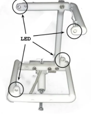
LED structure
For the POSIT algorithm a xed position of the lights should be used, so a structure to support the LEDs is necessary. Due to the limitations of the POSIT algorithm, the points can not be coplanar, so a cube with 4 light in alternative vertexes is used (gure 1.16). It is necessary to select one reference point to the POSIT algorithm, in this case the lower left light is our reference point, and the rest of the points are in clockwise order.
Figure 1.16.: Image of the LED structure used in this project. USB
The USB protocol is a well known wired communication protocol. In our case the USB protocol is used to establish the communication between the microcontroller and a device capable of act as USB host. The conguration of the USB protocol is a very extensive topic so only the mouse descriptor will be commented. The base is a common mouse descriptor available as an example in the HID Descriptor Tool for the USB Webpage36. In this example the descriptor is for a mouse
with 3 buttons, 2 axis of movement, and the wheel, but for our project, a customized version is used.
1 static uint8_t PROGMEM mouse_hid_report_desc [] = { 2 0x05 , 0x01 , // Usage Page ( Generic Desktop ) 3 0x09 , 0x02 , // Usage ( Mouse )
4 0xA1 , 0x01 , // Collection ( Application )
5 0x05 , 0x01 , // Usage Page ( Generic Desktop ) 6 0x09 , 0x30 , // Usage (X) 7 0x09 , 0x31 , // Usage (Y) 8 0x15 , 0x00 , // Logical Minimum (0) 9 0x26 , 0x00 , 0x08 , // Logical Maximum (2048) 10 0x35 , 0x00 , // Physical Minimum (0) 11 0x46 , 0x00 , 0x08 , // Physical Maximum (2048) 12 0x75 , 0x10 , // Report Size (16) , 13 0x95 , 0x02 , // Report Count (2) ,
14 0x81 , 0x02 , // Input (Data , Variable , Absolute ) 15 0 xC0 // End Collection
16 };
With this descriptor the data that the USB host waits for is two blocks of 16 bits. Both blocks have to send the values between 0 and 2048, and the host will translate them as absolute movement in the X and Y axis.
libusbx
The libusbx37 is a library that provides methods and functions to easily access to USB devices. It
is a fork of libusb38 which is less updated, so the libusbx is used.
The only conguration needed is to include the library directory in the linker. In the GCC compiler, with the Eclipse IDE, it is done by adding in the project properties the path and the library, or by adding the following line in the linker.
-L"<...>/LibUSB-Win32/lib/gcc" -lusb-1.0 Qt
Qt is a development framework to build applications and user interfaces for dierent platforms. The framework contains tools designed to speed up the development of the GUIs. The Qt code is reusable and the same code can be compiled to run on Windows, Linux or MAC, among others. This framework was selected for all the mentioned reasons, so it is used to make the PC program. For this project the version 4.8.4 is used. It can be downloaded from Qt download web page39.
Once downloaded the installation use 1.8 GB of hard drive.
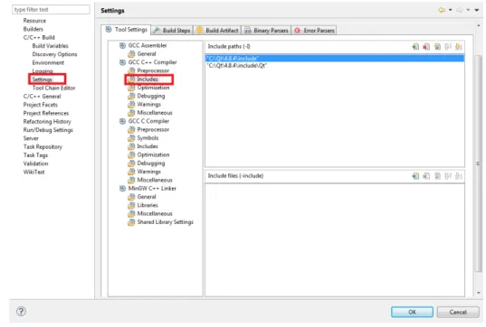
In order to compile Qt code, an IDE is provided in the framework. However, the compilation of code, in which the lib-usb library was necessary, had some issues with MinGW (Windows GNU compiler). Therefore to write the code, the Eclipse IDE is used since it provides autocompletion when working with custom classes. To get the autocompletion with the Qt classes, the includes les have to been included in the properties of the project, as can be seen in gure 1.17.
With this conguration the Eclipse helps when writing the code providing autocompletion, however in order to compile the Qt code the command line has to be used.
37http://libusbx.org/ 38http://www.libusb.org/
Figure 1.17.: Includes conguration in Eclipse for autocompletion with Qt libraries. According to Qt tutorials around the web the following steps have to been followed to compile:
1. qmake -project 2. qmake
3. make
The rst command generate the .pro le. This le contains some directives so the qmake can cre-ate a correct Makele to the make. However, in our project the lib-usb has to be included in order to enable USB communication with the Teensy. In order to do that the -L<lib_usb_dir> -lusb1.0 parameters should be added to the linker. The qmake -project does not add the necessaries lines in the .pro le so the makele fails when try to link the lib-usb library.
To x this, the next line, in the case of using Windows, should be added in the .pro le to include the library:
LIBS += -L"<...>/LibUSB-Win32/lib/gcc" -lusb-1.0
The qmake -project generates a dierent .pro le if the project has new les or libraries. Then, as long as no new les are added to the project, the qmake -project command and manual editing of the .pro le can be avoided.
2.1. Hardware research and design
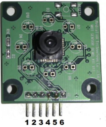
The rst job in the hardware part was to discover how the camera is connected and which are the function of all the six pins it has. The camera were joined with a PL2303HX1 which convert the
data from the camera from the UART protocol to USB so it can be connected to the PC. The rst task was to check the pins while the system was working.
Figure 2.1.: Frontal image of the camera with the PINs numbered as in the schematic. First, with the multimeter the DC pins were discovered, these pins are 1, 3 and 6, which are the ground, the reset and the supply respectively. Following the traces from the UART-USB bridge to the camera, the pins 4 and 5 turn out to be for transmission and reception. The last pin, the number 2 was unused, so it was the most dicult to understand. But after connecting it to an oscilloscope the clock signal was found out. This pin is and extra pin, that can be used to get the clock signal from the oscillator in the camera.
Once the camera was understood, the hardware design consists in the physical connection of the Teensy2++ module with the camera. The camera works with 3.3V in the data lines while the Teensy is congured to work with 5V, so the main task in the hardware design was to connect them with the right voltages. In the Teensy webpage2 explains how can it be congured to work
with 3.3V. The connection between them can be done:
• Directly if the modication to 3.3V is used in the Teensy.
• With some interface between the Teensy and the camera that adapts the voltages.
The rst option, using 3.3V modication, implies that the microntroller has to work at 8Mhz since 16Mhz can only be achieved with 5V. This project is oriented to real time processing, so the
1http://www.electronicaestudio.com/docs/PL2303.pdf 2http://www.pjrc.com/teensy/3volt.html
frequency of the microcontroller has to be as high as possible, so it can do more operations per second. This option is therefore rejected.
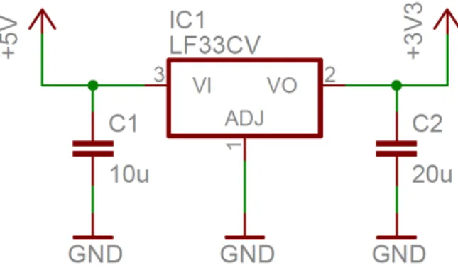
The second option consists in adding an interface between them. As the Teensy is working with 5V we have to adapt the data and the supply lines. For the constant supply the easiest way is to use a voltage regulator LF33CV which converts the voltage from 5V to 3.3V. The conguration is as shown in gure 2.2. This circuit supply constant 3.3V in the supply pin of the camera.
Figure 2.2.: Schematic conguration of the voltage regulator with the stability capacitors. With the supply voltage for the camera, the necessary voltages in the data lines can be calculated so the microcontroller and the camera detects zero as zero and one as one. To achieve that, it is necessary that the voltages in the devices full the requirements shown in table 2.1. According to the table, the transmission is possible in both ways. However, the maximum input voltage for the IO ports of the PAC7001CS is 3.6V, so an interface in need to down the voltage output from the AT90USB1286 to 3.3V.
PAC7001CS AT90USB1286 Input high voltage ≥2.31 ≥3
Input low voltage ≤0.99 ≤1
Output high voltage ≥2.97 ≥4.2
Output low voltage ≤0.33 ≤0.7
Table 2.1.: Electrical requierements for the data communcation
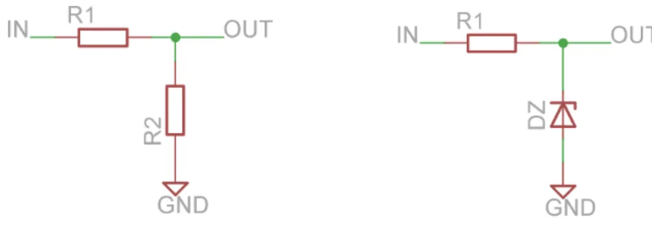
For the data transmission, the bandwidth of the elements is important, so the supply regulator cannot be used. Two options were considered: using a Zener diode of 3.3V or a voltage divider build from resistors. The Zener system would consist in a resistor in series with a Zener diode, the diode would let the necessary current ow so the voltage drop at the diode is 3.3V while the rest would drop in the resistor. The two resistors in parallel will do the same work but with a higher bandwidth. In that system the voltage drop at the rst resistor, when the input is 5V, has to be 1.7V and 3.3V in the second resistor. This second approach is simpler and cheaper so it is the implemented one.
For the calculations of the resistor values, we have to take into account which is the maximum current in the pins of the microcontroller and camera. The AT90USB1286 can output up to 40mA of current. However, there is no data about the maximum input current.
Figure 2.3.: Implementations of the voltage divider with the resistors and the Zener diode. Vi−Vo R1 = Io+ Vo R2 (2.1) Vi−Vo R1 < 40mA (2.2)
From the second equation we can get the lowest possible value for R1 is 42.5Ω. The output
current will depend on the R1 and since the limit value is 42.5Ωwe select a higher value so the
necessary current from the microcontroller pin is lower than the limit. The selected value for R1
is 2.2KΩ. With this value of R1, and if Vo is 3.3V, then the current from the I/O pin of the
microcontroller will be 0.77mA. From the equation 2.1 and the values obtained, we can derive: Io= 5−3.3 2.2KΩ − 3.3 R2 = 0.77mA−3.3 R2 (2.3)
With R2 = 2.2MΩthe current that will be derived to the camera will be 0.769 mA which is
not a high value, therefore the design of the interface can be seen in the next table: Name Value
R1 2.2KΩ
R2 2.2MΩ
Ii 0.77 mA
Io 0.769 mA
Table 2.2.: Design parameters for the interface microcontroller-camera
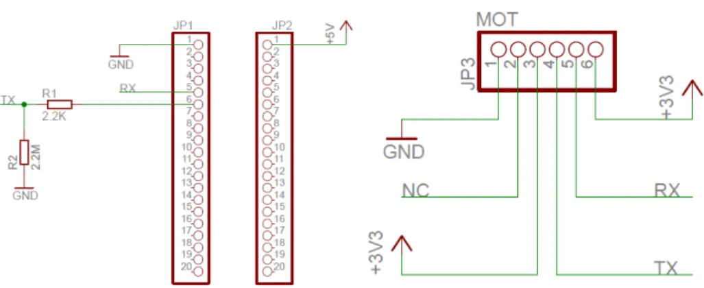
With the design of the interface, and once the function of the pins of the camera is known, the nal step is to connect everything together with the microcontroller. From the microcontroller only the UART TX and RX pins are used (pins 5 and 6 from the diagram, D2 and D3 from the Teensy2++ reference). The connection can be seen in gure 2.4. The 3.3V source comes from a part of the circuit shown in gure 2.2.
2.2. Software design
The implementation of the software part is done in C language. The IDE used is the Eclipse with the AVR plug-in and compiled with avr-gcc. The software can be structured in modules in order
Figure 2.4.: Connection diagram of the Teensy2++ and the camera
to abstract the hardware and the basic operations of the microcontroller. In gure 2.5 it is shown how the software is divided in modules that only depend on the layer beneath them.
In order to abstract all the microcontroller registers and variables, the functions to operate the UART, the FIFO and the USB are implemented. This method allows to program the software in a more readable way. The main software uses these libraries to access the more basic functions of the Teensy. These libraries also use the set of registers and instructions provided by the AVR-GCC library, which connects the software layer with the hardware layer. The physical elements of the microcontroller are found in the hardware layer.
2.2.1. Software overview
The main task of the software is to turn on the camera, get the object's coordinates and send the orders to the PC or device through the USB. For this purpose the software can be divided into simpler tasks:
• Congure the microcontroller. • Turn on and congure the camera. • Get the data from the camera.
• Apply the POSIT algorithm to the data. • Send the data through the USB.
The rst task is to congure the microcontroller. In this step the software turns on the services that are necessary in the next steps, also the FIFO queue is initialized, the clocks, USB and UART are turned on and congured. The interruptions of the USB and UART are enabled, so after this point the software does not need to congure or initialize protocols or pins, it just uses them.
Once all the systems inside the microcontroller are turned on and congured, the next step in to congure the devices outside of the AT90USB1286. In this project the only device that needs conguration outside the microcontroller is the camera. In this part of the process the camera is turned on and checked for possible errors. Once the correct message is received from the camera, the next step is to congure the registers of the camera for our purpose. The registers are set and then the camera is turned to Operation mode. In this mode the camera starts sending data of the objects it tracks. The data is stored in a FIFO queue which has been initialized in the rst step.
With the data of the camera in the FIFO queue, the next step is to get the data and store it in an easier way to handle. The data of the camera comes in frames of data which are separated into structures that store the data in more human-readable format. Once the structures are lled with the necessary data, de POSIT algorithm is applied. The POSIT algorithm works with matrices of data, so the required values of the structures are therefore stored in matrix form before applying the algorithm.
From the FIFO algorithm we get the translation and rotation vectors for the camera. With this data the software has to calculate the coordinates for the mouse pointer to send them through the USB. For testing purposes there are two USB endpoints, the mouse endpoint and the debug endpoint. In the last one some debug information is sent and can be visualized in the PC.
2.2.2. Data format and structures
For the dierent parts of the project some structures and data formats are used. The rst step in our software is to get the data from the camera. The data is sent at 115200 baud per second, which is the baud rate that allows to send a full frame (four object in a frame,table 1.2). Depending on the processing speed of the data, a real time processing system can be achieved. For that reason, it is necessary to save the data obtained by the camera during the processing, in some buer, so no data is lost. In this case, a circular FIFO queue was selected to act as the buer for the UART input data. Due to simplicity purposes only the basic operations are implemented. The security checks are also kept at minimum. The structure that allocates the main variables of the FIFO queue is shown below.
typedef struct{
unsigned char *pwrite; unsigned char *pread; unsigned char *end; unsigned char *buffer;
volatile unsigned int count; }fifo_t;
The FIFO queue consist on 4 pointers, pwrite, pread, end and buffer. The rst two ones are used when read or write operations are implemented. pwrite points to the rst available position to write, so when a write operation is necessary, the library writes where pwrite points and increments its position. If the end of the queue is reached (pwrite = end) then the new data is written in pwrite and after that the pointer is set to buffer. For the read operation the operations are the same but the read operation will fail if pread is equal to pwrite. The pread pointer points to the data to be read.
Figure 2.6.: Representation of the FIFO queue with its pointers. The operations that are implemented for this queue are the followings ones: void fifo_init(volatile fifo_t *fifo, unsigned char *buf); char fifo_push(volatile fifo_t *fifo, unsigned char byte); unsigned char fifo_pop(volatile fifo_t *fifo);
unsigned char fifo_empty(volatile fifo_t *fifo); unsigned char fifo_full(volatile fifo_t *fifo); void fifo_reset(volatile fifo_t *fifo);
Only the most important functions of the queue are implemented, the fifo_push and fifo_pop functions are to write and read respectively. In case of fifo_pop the returned value is the read data, while in fifo_push, the return value is a value representing the correctness of the operation.
The fifo_empty and fifo_full are auxiliary functions which return if the FIFO is empty or full respectively. The function fifo_reset is used to empty the FIFO queue. In pop and reset cases even if the data is read or deleted, it is still stored only the pointers of the FIFO change. Finally the fifo_init initialize the FIFO queue, the input parameter is the FIFO to be initialized and a buer (already initialized) which will store the data of the queue. With this functions the FIFO is fully operational for our purpose. In this project the FIFO is fullled with the data, but once the data necessary for the processing has been acquired the UART stop receiving data. Then FIFO is reset at the end of the processing so the available data is the newest one. The software does not need too much memory, therefore the length of the FIFO is set to 1024, that is bigger than we need. However, the available memory is not a problem.
Once the data is stored in the FIFO queue it is necessary to store it in more human readable format, for this purpose, in les PAC7001.h and PAC7001.c, the next structures and functions can be found. typedef struct{ uint8_t FlagByte; uint8_t ObjFlagByte; uint16_t CenterX; uint16_t CenterY; uint16_t Size; uint8_t EOB; }Objects; typedef struct{
unsigned char Header[4]; Objects obj[4];
}CamFrame;
The function of these structures is to store the data from the camera, which come in a burst of bytes, in a more ordered manner. The structure of the struct Objects depends on how the camera sends the data, especially in how the register Feature option enable ag is congured, in our case this value will be 0x93 which correspond with the structure shown above. There are two structures, one for each object and the other for the full frame. The Header of the CamFrame is necessary to identify when a frame starts and to check that everything is working as expected, since if a header is dierent from 0xFF00FFFF something has gone wrong. With these structures the following function can be used.
int FrameCheckHeader(CamFrame *Frame);
int FrameFlagByte(int Getinfo, Objects *obj); int FrameObjectCheck(int Check, Objects *obj);
unsigned char ProcessData(unsigned char* buffer, CamFrame *Dest);
void PACSetRegister(unsigned char RegNum, unsigned char RegValueHigh,unsigned char RegValueLow); void PACReadRegister(unsigned char RegNum);
void SwitchMode(unsigned char Mode);
The names of the functions are in most of the cases self-explanatory but a small overview will be done. The FrameCheckHeader check if the header of a CamFrame structure is correct. The next function,FrameFlagByte, is used to check if the object has been tracked or not, or to get
the frame number. The FrameObjectCheck is an auxiliary function to check the rst bit of the Flag Byte and Object Flag Byte, which have to be one in both cases, if not an error has occurred. In ProcessData is where most of the work is done. This function takes as input the burst of bytes from the camera and store them in a structure. The rst step is to recover the header and check it, if there is an error with the header, then the rest is rejected. If the header is correct the rest of the data is stored in the structure for future processing. The PACSetRegister and PACReadRegister work with the camera through the UART. These functions set and read de register, for the set operation RegValueHigh is only used in two register(the two registers with 2 bytes, IW and IH). The last function is used when the camera has to be changed from Initial Mode to Operation Mode and vice versa. These are the necessary functions to move the data from the buer to structures, and then do the checks. With the data in the structure the nal step is to apply the POSIT algorithm to the data.
In the POSIT algorithm some matrix and vectors are used. For the vectors the structure is a normal array, in which every position of the array corresponds to one element in the vector. For the matrix there are dierent possibilities:
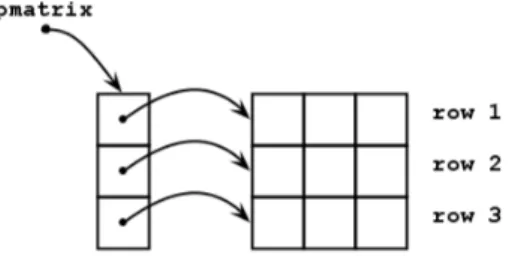
• Arrays of arrays: In this case the pointer to the matrix will point to an array of pointers
in which each pointer point to another array representing the row or column of the matrix. This format forces the processor to access one pointer, then move through the array, read the pointer and move to another array doing therefore lots of work to access one element of the matrix.
Figure 2.7.: Representation of a matrix build as an array of arrays.
• All in a row: this kind of matrix representation store all the matrix in one array in which
the rows or columns are stored one row after another. This scheme is faster since only one address has to be accessed, the pointer to the matrix. Supposing pmatrix is a pointer to the matrix array storing a mxn matrix, to access one element the code will be pmatrix[COL*n+ROW] with the COL and ROW starting at 0.
For the implementation of the POSIT algorithm the second option is used, storing one row after another. This method improves the speed and memory performance.
2.2.3. Actual block diagram
With the data structures and format the main program can be explained. The full block diagram can be seen in gure 2.9. The rst step in the software is to congure the AT90USB1286 microcontroller so it can handle all the system that will be used.
Figure 2.9.: Full software block diagram.
Figure 2.10.: Initialization procedure.
In the AVR initialization (gure 2.10) block the UART is turned on with a baud rate of 19200 baud ,which is the default baud rate that the camera has, when it turns on. Then the UART is congured to work with the camera protocol, that means with no parity bit nor stop bit and words of 8 bits. The UART of our microcontroller has the double speed option to achieve higher speeds of transmission. For the rst baud rate high speed is not necessary, however when the UART has to work at 115200 Bd, the high speed register is set. In le uart.h the UART initialization function can be found as:
void uart_init(unsigned long baud_rate, unsigned char double_speed)
This function has to calculate the baud rate that the registers of the UART need. This value,when double speed is o, is calculated:
Baud rate to registers= CPU freq.
When double speed is on, the factor 16 changes to 8. The value obtained from the last equation is used in the registers UBRR1H and UBRR1L. The UBRR1H register stores the most signicant bits of that value, while the rest is stored in UBRR1L. When the baud rate is set in the registers, the transmission and reception are enabled with no parity, 1 bit stop and character size of 8 bits with: UCSR1B = _BV(TXEN1) | _BV(RXEN1); //Enable Tx and Rx
UCSR1C = ~_BV(UPM11) | ~_BV(UPM10); // No parity UCSR1C = ~_BV(USBS1); //1 bit stop
UCSR1C = ~_BV(UCSZ12) | _BV(UCSZ11) | _BV(UCSZ10); //character size 8-bits To send data through the UART the function uart_send_byte is used:
void uart_send_byte(unsigned char byte) {
while ( !( UCSR1A & (1<<UDRE1)) ); UDR1=byte;
}
This function waits until the bit UDRE1 (USART Data Register Empty) in the register UCSR1A is set to zero. That means that the transmit buer of the UART is empty and ready to receive more data. In that moment the data to be sent is stored in register UDR1, which will send the data as soon as possible. When the software needs to send a byte through the UART, this function will be used in order to abstract from how the microcontroller is doing it.
After turning on and conguring the UART, interrupts from UART receives are activated. Following the UART initialization comes the USB, with the activation of the USB pins and internal registers, the internal PLL for clocking the USB pins and the interruptions are enabled. The USB code comes in an example in the webpage of the Teensy2++, the USB mouse example3,
but after some changes it is suitable for our proyect. In order to identify the USB in the PC or USB host, the USB device has to be congured with some product ID and vendor ID. In our case the values for this parameters are dened as:
#define VENDOR_ID 0x16C0 #define PRODUCT_ID 0x047F
The communication between the device and the host is done through two pipes. The conguration of these pipes can be seen in table table 2.3.
Interface Endpoint Type Use
0 3 IN Mouse data
1 4 IN Debug data
Table 2.3.: Pipes conguration for USB communication.
For the data format in the USB frames, the example comes with a simple mouse implementation, 2 axis, a wheel and 3 buttons, and a debug descriptor. The debug descriptor can be used without any change, however the descriptor of the mouse has to be adapted to our project. The example descriptor of the mouse is:
1 static uint8_t PROGMEM mouse_hid_report_desc [] = { 2 0x05 , 0x01 , // Usage Page ( Generic Desktop ) 3 0x09 , 0x02 , // Usage ( Mouse )
4 0xA1 , 0x01 , // Collection ( Application ) 5 0x05 , 0x09 , // Usage Page ( Button )
6 0x19 , 0x01 , // Usage Minimum ( Button #1) 7 0x29 , 0x03 , // Usage Maximum ( Button #3) 8 0x15 , 0x00 , // Logical Minimum (0)
9 0x25 , 0x01 , // Logical Maximum (1) 10 0x95 , 0x03 , // Report Count (3) 11 0x75 , 0x01 , // Report Size (1)
12 0x81 , 0x02 , // Input (Data , Variable , Absolute ) 13 0x95 , 0x01 , // Report Count (1)
14 0x75 , 0x05 , // Report Size (5) 15 0x81 , 0x03 , // Input ( Constant )
16 0x05 , 0x01 , // Usage Page ( Generic Desktop ) 17 0x09 , 0x30 , // Usage (X) 18 0x09 , 0x31 , // Usage (Y) 19 0x15 , 0x81 , // Logical Minimum ( -127) 20 0x25 , 0x7F , // Logical Maximum (127) 21 0x75 , 0x08 , // Report Size (8) , 22 0x95 , 0x02 , // Report Count (2) ,
23 0x81 , 0x06 , // Input (Data , Variable , Relative ) 24 0x09 , 0x38 , // Usage ( Wheel )
25 0x95 , 0x01 , // Report Count (1) ,
26 0x81 , 0x06 , // Input (Data , Variable , Relative ) 27 0 xC0 // End Collection
28 };
The rst problem with this implementation is that in our case we are not moving the mouse relatively but absolute to where the head is pointing, so the rst step is to change the move from relative to absolute, changing the line 23 from:
0x81, 0x06,// Input (Data, Variable, Relative) to
0x81, 0x02,// Input (Data, Variable, Absolute)
In our project the wheel and buttons are not used. Therefore, the following lines are deleted: 0x05, 0x09,// Usage Page (Button)
0x19, 0x01,// Usage Minimum (Button #1) 0x29, 0x03,// Usage Maximum (Button #3) 0x15, 0x00,// Logical Minimum (0) 0x25, 0x01,// Logical Maximum (1) 0x95, 0x03,// Report Count (3) 0x75, 0x01,// Report Size (1)
0x81, 0x02,// Input (Data, Variable, Absolute) 0x95, 0x01,// Report Count (1) 0x75, 0x05,// Report Size (5) 0x81, 0x03,// Input (Constant) ... 0x09, 0x38,// Usage (Wheel) 0x95, 0x01,// Report Count (1),
When trying to run the software with this USB descriptor the range of movement of the pointer was so limited because for relative movement, with a range between 0 and 127, is enough reso-lution. However for absolute movement 127 dierent points are not enough, so the resolution is changed in lines 19 and 20. Since the resolution necessary is higher than 255 points, the size of the report will also be increased from 8 bits to 16 bits.
0x15, 0x81, // Logical Minimum (-127) 0x25, 0x7F, // Logical Maximum (127) 0x75, 0x08, // Report Size (8), 0x95, 0x02, // Report Count (2), to 0x15, 0x00, // Logical Minimum (0) 0x26, 0x00, 0x08, // Logical Maximum (2048) 0x35, 0x00, // Physical Minimum (0) 0x46, 0x00, 0x08, // Physical Maximum (2048) 0x75, 0x10, // Report Size (16), 0x95, 0x02, // Report Count (2),
With all this changes the USB descriptor t our purpose and therefore is used. The nal descriptor is as shown:
1 static uint8_t PROGMEM mouse_hid_report_desc [] = { 2 0x05 , 0x01 , // Usage Page ( Generic Desktop ) 3 0x09 , 0x02 , // Usage ( Mouse )
4 0xA1 , 0x01 , // Collection ( Application )
5 0x05 , 0x01 , // Usage Page ( Generic Desktop ) 6 0x09 , 0x30 , // Usage (X) 7 0x09 , 0x31 , // Usage (Y) 8 0x15 , 0x00 , // Logical Minimum (0) 9 0x26 , 0x00 , 0x08 , // Logical Maximum (2048) 10 0x35 , 0x00 , // Physical Minimum (0) 11 0x46 , 0x00 , 0x08 , // Physical Maximum (2048) 12 0x75 , 0x10 , // Report Size (16) , 13 0x95 , 0x02 , // Report Count (2) ,
14 0x81 , 0x02 , // Input (Data , Variable , Absolute ) 15 0 xC0 // End Collection
16 };
The way the data is send to the computer has changed from 2 buttons, wheel and axis to only the axis, with 2 bytes for each axes. Therefore, the function that send the data to the computer need to be changed in order to send the correct data.
1 int8_t usb_mouse_move ( int16_t x, int16_t y, int8_t wheel ) 2 {
3 ...
4 /* keeps the same */ 5 ... 6 7 UEDATX = LSB (x); 8 UEDATX = MSB (x); 9 UEDATX = LSB (y); 10 UEDATX = MSB (y); 11 12 13 UEINTX = 0 x3A ;
14 SREG = intr_state ; 15 return 0;
16 }
With the mouse data, the USB has to send the debug messages. The debug endpoint of USB and the function to operate it are included in the example program and need no change. For the use of the debug endpoint there are dierent functions to send data as numbers or strings. The function print_P is used to send complete strings through the USB debug endpoint. This function can be accessed through the print function. For numbers there are two options: phex and phex16, they should be used with 1 byte or 2 bytes numbers respectively. Their prototypes are:
void print_P(const char *s); void phex(unsigned char c); void phex16(unsigned int i);
All of this functions use the usb_debug_putchar. This function sends the characters through the USB. It waits until the USB lines are ready to transmit. Then, it selects the debug endpoint to transmit the data, and store it in the FIFO queue for the USB transmission. Once the USB has a complete packet of data, it sends it. The print_P function reads all the characters of a string and use the usb_debug_putchar to send them, one by one.
Figure 2.11.: Flowchart to set camera's registers.
The USB is the last system that needs to be initialized in the microcontroller, so once the USB has been congured, the next step is to turn on the camera, congure it and start receiving data (gure 2.11). The camera needs the 0xEA command to be turned up so it is sent, followed by a 0x8E just to be sure that the camera is in Initial Mode. In that mode the camera's registers can be set up, the values of them vary between applications and the actual values for each test will be commented on the tests part. After setting all the values of the registers the baud rate of the communication is set to 115200 baud. Then, in the debug window it is checked that the Tracking V01 message and the ACKs from the camera are received. If everything were as expected the camera is changed to Operation Mode and the main loop of the program starts.
The main loop (gure 2.12) starts with a delay of 100 ms waiting for the data to arrive, until there are not enough bytes of data in the buer the algorithm keeps waiting. When there is enough data the FIFO is read until a header (0xFF00FFFF) is found which means that from that point the buer can be passed to the ProcessData function and be stored in a CamFrame structure. If the data is processed and there are not errors, then each of the objects in the frame is checked with FrameFlagByte function which checks the bit of the byte that represent if the object has been tracked or not. If is the case then the necessary operations are applied, in some cases is to
Figure 2.12.: Flowchart from the main loop of the software. The options A and B are for using the data with the POSIT algorithm or debugging it at PC.
send the data through the debug channel to be analyzed with some PC software, in other cases the data of the four objects are stored and passed to the POSIT algorithm.
For the POSIT algorithm the matrices A and B are necessary, as shown in the methods sections. The matrix A is constructed with the vector connecting the reference point with each of the others points. The order in which the objects are included in the matrix has to be the same as the order in which the objects are sent to the POSIT algorithm. That is, if the rst element in the matrix is the vector connecting the reference point to object a, then the rst element in the array of data, for the POSIT, has to be the image coordinates of that object a.
The tracked objects are, therefore, arranged in the same way that in the matrix for the POSIT. In the devices section we can see how is the structure for the LEDs (gure 1.16). The reference point is the lower left one, and then the objects are arranged in the matrix in clockwise order. In order to arrange them like that, the rst step is to look for the reference point, which will be the one which has less Y value, from the two objects with higher X value (supposing that the camera orientation is as in the images, X axis vertical, Y axis horizontal).
The algorithm to order the objects will be: 1. Order all the elements in increasing X order.
2. From the two with higher X value, select the one with lower Y value, as reference point, and the other as last point.
3. From the two with lower X value, the one with lower Y will be the rst point, and the other one the second point.
This method, of detecting which object is the rst one and so on, includes a restriction in the pose detection. In some angles (extreme angles), the objects can be wrong assigned since the top objects are treated like bottom ones. The position, of the camera and the LED structure, necessary to achieve these angles are not common in normal use.
The data from the camera is referred to one corner of the image, however for the POSIT algorithm it is necessary that the coordinates are referred to the center of the image, so the rst step in the POSIT algorithm is to refer the coordinate to the center. Then the needed variables are created and initiated, for theεvalues there are 2 arrays, one for the current iteration and the other one for the last one, so at the end of the iteration they can be compared. The values ofx0
andy0 are calculated:
x_[0] = x[1]*(1 + eps0[0]) - x[0]; x_[1] = x[2]*(1 + eps0[1]) - x[0];
![Figure 1.15.: Points in real world and their projection in the image plane[17]](https://thumb-us.123doks.com/thumbv2/123dok_us/10986352.2986426/22.892.321.596.126.474/figure-points-real-world-projection-image-plane.webp)