Innovative Systems Design and Engineering www.iiste.org ISSN 2222-1727 (Paper) ISSN 2222-2871 (Online)
Vol.4, No.10, 2013
A Proposed Approach to Mechatronics Design and
Implementation Education-Oriented Methodology
Farhan A. Salem
Alpha center for Engineering Studies and Technology Researches, Amman, Jordan.
Mechatronics program, Department of Mechanical Engineering, Faculty of Engineering, Taif University, 888, Taif, Saudi Arabia.
Email: [email protected] Ahmad A. Mahfouz
Department of Automatic and Mechatronics Systems, Vladimir State University, Vladimir, RF Alpha center for Engineering Studies and Technology Researches, Amman, Jordan. Email:
Abstract
Mechatronics engineer is expected to design engineering systems with synergy and integration toward constrains like higher performance, speed, precision, efficiency, lower costs and functionality. The key element in success of a mechatronics engineering education-program, and correspondingly, Mechatronics engineering graduates, is directly related to a well-structured mechatronic system design course and the applied structural design methodology. Guidelines for structural design methodology and tools for the development process of mechatronic products, that can be applied in educational process is highly required. This paper proposes mechatronics systems design education-oriented methodology, which aims to integrate multidisciplinary knowledge, in various stages through the design process and development of mechatronics product. The proposed mechatronics design methodology is described, discussed and applied with the help of example student final year graduation project; design and implementation of mechatronics mobile robotic guidance system in the from of smart wheelchair- Mechatronics Motawif, to help and support people with disabilities and special needs to perform specific predetermined tasks, particularly, performing Al Omrah and motion around holy Kaba, Makka.
Keywords: Mechatronics, Design methodology, Parallel design, Synergistic integration, Modeling/ Simulation,
Prototyping, Mobile robot, Motawif
1. Introduction
The modern advances in information technology and decision making, as well as the synergetic integration of different fundamental engineering domains caused the engineering problems to get harder, broader, and deeper. Problems are multidisciplinary and require a multidisciplinary engineering systems approach to solve them, such modern multidisciplinary systems are called mechatronics systems, correspondingly, engineers face daunting challenges, and to be competitive, in labor market, engineers must provide high value by being immediate, innovative, integrative, conceptual, and multidisciplinary, engineers must have depth in a specific engineering discipline, as well as multidisciplinary engineering breadth, with a balance between theory and practice, in addition, they must have breadth in business and human values, an engineer with such qualifications is called Mechatronics engineer.
Mechatronics engineer is expected to design products with synergy and integration toward constrains like higher performance, speed, precision, efficiency, lower costs and functionality, and in order to evaluate concepts generated during the design process, without building and testing each one, the mechatronics engineer must be skilled in the modeling, analysis, and control of dynamic systems and understand the key issues in hardware implementation [1]. The key element in success of a mechatronics engineering program, and correspondingly Mechatronics engineering graduates, is directly related to the applied structural design methodology, and engineering educators face daunting challenges, where due to different disciplines involved, the mechatronics design process may become very complex, therefore specific guidelines for structural design methodology and tools for the development process of mechatronic products, that can support students in solving mechatronics design tasks with their specific properties and can be applied in educational process is highly required. This paper proposes mechatronics design education-oriented methodology, which aims to integrate multidisciplinary knowledge, in various stages including; pre-study process and problem statement, conceptual design, optimal selection and synergistic integration, modeling, simulation, prototyping, analysis and physical implementations in development of mechatronics product and to fulfill above desired requirements.
There are many definitions of mechatronics, regardless of the definition, Mechatronics is defined as multidisciplinary concept (Figure1(a), it is synergistic integration of mechanical engineering, electric engineering, electronic systems, information technology, intelligent control system, and computer hardware and
Innovative Systems Design and Engineering ISSN 2222-1727 (Paper) ISSN 2222-2871 (Online Vol.4, No.10, 2013
software to manage complexity, uncertainty, and communication through the design and manufacture of products and processes from the very start of the design process, thus enabling complex decision making. Modern products are considered mec
fully integrated electronics, intelligent control system
complex products, considering the top two drivers in industry today for i
are shorter product-development schedules and increased customer demand for better performing products, demand another approach for efficient development.
challenges, it is a modern interdisciplinary design procedure, is it the concurrent selection, evaluation, integration, and optimization of the system and all its sub
all the design disciplines work inparallel
produce an overall optimal design–
shortened development, also allows the design engineers to provide feedback to e
of design is effect by others. Industrial and scientific evolutions of mechatronic products have led to substantial experience, and as a natural consequence industrial guideline have emerged for the product design of mechatronic products. [2]. Depending
educational recourse introduce different design approaches and models, including [2
role in these guideline methodology models are based on VDI2206 (2003) guideline, which is devoted particularly to the design methodology for mechatronics systems and suggests to carry out the development process of mechatronics according to so called V
from software engineering and adapted for mechatronic
aim is to establish a cross-domain solution concept which describes the main physical and logical operating characteristics of the future product,
requirements of the total system, the sub
simultaneously by the cooperating development teems, Next ( Base side of V
testing sub-systems through modeling and model analysis in mechanical engineering, electrical engineering and information technology domains. Next (Right side of V
are integrated, and the performance of the integrated system is c operation phase can be repeated. The proposed
VDI 2206 guideline and different
consists of a systematic specific simple and clear design steps (shown in diagram 2(a)(b) ) that can help and support engineering educators, non experienced student or group of students, easy to memorize and follow, in solving mechatronics design tasks,
help of example student graduate project
The modern advances and synergetic integration of different domains caused the application f mechatronics systems to differentiate into the conventional mechatronic and Microelectromechanical micromechatronic systems – MEMS (deals with classical mechanics and electromechanics) and nanoelectromechanical- nanomechatronic systems
nanoelecctromechanics)[3].
(a) (b) V Figure 1 (a) Basic principle
Innovative Systems Design and Engineering 2871 (Online)
software to manage complexity, uncertainty, and communication through the design and manufacture of products and processes from the very start of the design process, thus enabling complex decision making. Modern products are considered mechatronics products, since, it is comprehensive mechanical systems with
intelligent control system and information technology. Such
considering the top two drivers in industry today for improving development processes, that development schedules and increased customer demand for better performing products, demand another approach for efficient development. The Mechatronic system design process addresses these
modern interdisciplinary design procedure, is it the concurrent selection, evaluation, integration, and optimization of the system and all its sub-systems and components as a whole and concurrently,
parallelandcollaboratively throughout the design and development process – no after-thought add-ons allowed. this approach offers less constrains and shortened development, also allows the design engineers to provide feedback to each other about how their part . Industrial and scientific evolutions of mechatronic products have led to substantial experience, and as a natural consequence industrial guideline have emerged for the product design of Depending on type of mechatronic system, different industrial, scientific and recourse introduce different design approaches and models, including [2-13][16][21][34]. A major role in these guideline methodology models are based on VDI2206 (2003) guideline, which is devoted ly to the design methodology for mechatronics systems and suggests to carry out the development process of mechatronics according to so called V-model (Figure1(b)); The proposed V-model has been adopted from software engineering and adapted for mechatronics requirements, which are distinct from
domain solution concept which describes the main physical and logical operating characteristics of the future product, the input (Left side) to this V-model is defining
requirements of the total system, the sub-functions and sub-systems are defined and to be developed simultaneously by the cooperating development teems, Next ( Base side of V-model) verifying sub
odeling and model analysis in mechanical engineering, electrical engineering and information technology domains. Next (Right side of V-model) the verified sub-function and tested sub
are integrated, and the performance of the integrated system is checked, if it has to be improved, the initial operation phase can be repeated. The proposed mechatronics education-oriented design methodology
VDI 2206 guideline and different industrial, scientific and educational recourse. the proposed method simple and clear design steps (shown in diagram 2(a)(b) ) that can help and support engineering educators, non experienced student or group of students, easy to memorize and follow, in
tasks, the proposed design steps to be applied, described and discussed with the help of example student graduate project-smart mechatronics mobile robot-Motawif.
The modern advances and synergetic integration of different domains caused the application f mechatronics systems to differentiate into the conventional mechatronic and Microelectromechanical
MEMS (deals with classical mechanics and electromechanics) and nanomechatronic systems– NEMS (deals with quantum theory and
(a) (b) V- model, VDI 2206 2003[2]
Basic principle; mechatronics circular-model, (b) Mechatronics design V
www.iiste.org
software to manage complexity, uncertainty, and communication through the design and manufacture of products and processes from the very start of the design process, thus enabling complex decision making. it is comprehensive mechanical systems with and information technology. Such multidisciplinary and mproving development processes, that development schedules and increased customer demand for better performing products, The Mechatronic system design process addresses these modern interdisciplinary design procedure, is it the concurrent selection, evaluation, systems and components as a whole and concurrently, hroughout the design and development process to ons allowed. this approach offers less constrains and ach other about how their part . Industrial and scientific evolutions of mechatronic products have led to substantial experience, and as a natural consequence industrial guideline have emerged for the product design of industrial, scientific and 13][16][21][34]. A major role in these guideline methodology models are based on VDI2206 (2003) guideline, which is devoted ly to the design methodology for mechatronics systems and suggests to carry out the development model has been adopted s requirements, which are distinct from case to case, the domain solution concept which describes the main physical and logical operating model is defining and analyzing all systems are defined and to be developed model) verifying sub-function and odeling and model analysis in mechanical engineering, electrical engineering and function and tested sub-systems hecked, if it has to be improved, the initial oriented design methodology is based on recourse. the proposed methodology, simple and clear design steps (shown in diagram 2(a)(b) ) that can help and support engineering educators, non experienced student or group of students, easy to memorize and follow, in
the proposed design steps to be applied, described and discussed with the The modern advances and synergetic integration of different domains caused the application field of mechatronics systems to differentiate into the conventional mechatronic and Microelectromechanical - MEMS (deals with classical mechanics and electromechanics) and ls with quantum theory and
Innovative Systems Design and Engineering www.iiste.org ISSN 2222-1727 (Paper) ISSN 2222-2871 (Online)
Vol.4, No.10, 2013
Figure 2(a) Guideline for mechatronics systems design education-oriented methodology Conceptual Design and functional specifications
Conceptual Model , functional specifications , block diagram; suggest preliminary; solutions, study of feasibility, costs and benefits
Pre-Study Process: The problem statement
User& System requirements , specifications & functions analysis and definitions
Parallel (Concurrent ) design , integration and optimization of all sub-systems: Mechanical, electric, Control, information processing Software,
Electronics, and interface
Actuator selection & integration
Type, load, Speed range, Positioning accuracy, Power and torque
requirements
Sensors selection & integration
stability, resolution, precision, type robustness, size, cost, and signal processing
Control unit selection, design & integration
Microcontroller, PLC , PC …
Modeling and simulation
(modular and detailed) Optimization
Prototyping and testing Virtual prototyping Physical prototyping
Once the developed system is tested, refined, and confirmed to satisfy the requirements and specifications Basic physical system
The whole system
Manufacturing and Commercialization
Mechanical design & integration
Optimal mechanical structure, dimensions, materials, type of joint, supports, DOF, System layout, Kinematics properties ,CAD
mode
Control algorithm & software Selection :ON-OFF control, PID control, intelligent control, Fuzzy control …
Selection and integration of human– machine interaction field
Control of the machine, and feedback from the machine
: user interface, input/ output means ;digital display, LCD, touch screens, voice activation
Output signal, conditioning and Interfacing design & integration
Selecting of power supplies, drive , signal processing , conditioning circuits , DAC, ADC, amplifiers ..to match the controller, sensor and actuators specifications and
ratings
Complete detailed system layout
Innovative Systems Design and Engineering www.iiste.org ISSN 2222-1727 (Paper) ISSN 2222-2871 (Online)
Vol.4, No.10, 2013
Figure 2(b) Guideline for mechatronics systems design education-oriented methodology
2. Proposed Guideline for mechatronics systems design education-oriented methodology
2.1 The Pre-Study Process- problem statement; it is the process of gathering as much information as possible
about the product and its future applications, all possible conditions of operation, the environmental factors, and the specifications with respect to quality, physical dimensions, and costs. Studying, analyzing and defining target user (Customer), user needs and requirements, system requirements, aesthetics, and target market, resulting in a
Pre-Study Process: The problem statement
User requirements identification, definition and analysis
a
System requirements identification, definition and analysis
b
Aesthetics
c d The problem statement
1
Conceptual Design, Conceptual Model and functional specifications and their structure.
2
Description of system in terms of an interdisciplinary set of integratedgeneral ideas and concepts
a
Analysis of tasks, sub-functions, overall function, Build system functional model
b
Build Morphological table and analysis, suggest solutions, evaluate the best solution
c
Build preliminary system’s block diagram & layout of main components
d
A preliminary study of feasibility, costs, and benefits
e
Parallel (concurrent) design and integration of sub-systems: Mechanical, Control, information processing Software, Electronics, and interface design and integration.
3
Parallel optimal selection, integration & optimization of modules, sub-systems , components and system as a wholeconcurrently throughout the design and development process Mechanical system Electric & Electronics
Divided the system into realizable modules
a
Sensors Actuators Signals, conditioning
and Interfacing Control unit Control algorithm Human–machine
interaction
Develop detailed system diagram layout
Modeling, simulation ,analysis and evaluating 4
Based on the specification of requirements and design, the subsystems models and the whole system model, are to be tested and analyzed to check whether the given design specifications are satisfied
Analytical modeling;Represent the sub systems and whole system using mathematicalequations suitable for computer simulation
a b
Physical (Experimental) modeling; b
Prototyping, testing, evaluation and optimization 5
Virtual Prototype: 3D model of a product presented in a virtual environment with, ideally, all information and properties included
a
b Physical Prototype: system integration to ensure s that subsystems,
components and whole system work together under operating condition
Manufacturing and Commercialization 6
Support, service and market feedback analysis 7 It er at e fo rw ar d an d ba ck w ar d , co nc ur re nt ly in te gr at e an d op ti m iz e th e sy st em a s a w ho le t o fu lf il l r eq ui re m en ts , no a ft er -t ho ug ht a dd -o ns a ll ow ed
Innovative Systems Design and Engineering www.iiste.org ISSN 2222-1727 (Paper) ISSN 2222-2871 (Online)
Vol.4, No.10, 2013
preliminary design specification, which has to be updated continuously according to the new information gathered during the development process.
2.1.1 User's requirements analysis; to acquire necessary information to identify, understand and discover
potential user, user's needs, interests, requirements and define system functions.
1) Understanding user requirements is an integral part of design and is critical to the success of final product.
2) users seldom know what they want or need, systems engineers must enter the customer's environment and find out the user need and requirements, and how the users will use the system, design must exceed, not merely meet, customer expectations, 3) Creativity of designers is required for the transfer of user requirements into innovative consumer product.
2.1.2 System requirements analysis; well-defined product requirements, to create a detailed functional
specifications and defining the full set of system capabilities to be implemented. There are two types of system requirements;
1) Fixed or Mandatory system requirements; the minimal requirements necessary to satisfy the customer's
operational need.
2)Soft or Tradeoff system requirements; after understanding the mandatory requirements, Engineers propose
alternative candidate designs, all of which satisfy the mandatory requirements. Then the tradeoff requirements are evaluated to determine the preferred designs. Treating user and system requirements as the same thing will create problems for projects.
2.1.3 Aesthetics In some instances this is not important, particularly where the device or structure is not seen.
However, for many consumer products or structures a pleasing elegant design is required and colour, shape, form and texture should be specified [14]
2.1.4 The problem statement: it is a list and description of problems that is given to a problem solving team as
a sort of brief, before they attempt to solve the problem. The problem statement is more important than problem solving, before attempting to find solution (design and built) for a given a problem, it is very important understanding what is problem and to state it in clear unambiguous manners and terms. The problem statement includes: description of what the problem, who has the problem, the user's needs, and user and system requirements, states the goals of the project, defines the business needs, prescribes the system capabilities and method used to solve the problem. The problem statement starts with a description of thetop-level functions that the system must perform, and it might be better to state the problem in terms of the deficiency that must be ameliorated [15]
2.1.2 The problem statement of ''Smart mechatronic robotic guidance system-Mechatronics Motawif in
the form of smart wheelchair''; Analysis of Local Makka Al-Mukarramah market, show a potential market for
commercialization of ''Smart mechatronic robotic guidance system-Mechatronics Motawif in the form of smart wheelchair''that can be used to help people with disabilities and special needs to perform Omrah, and feel safer about their surroundings. The potential users want the wheelchair; to be used as smart mechatronics Motawif to help and guide them in performing all Al-Omrah rituals and motions, particularly, eliminates the support and/or help from other peoples, easy to use and to maneuver, moves and stops are accomplished with suitable speed and with minimum kicks (overshoot), simple and easy to understand and use interface, cost-efficient operate on lower costs, a stable seating, seat to be level, suitable backrest angle that should provide support and balance for the upper body, A chair that is versatile/adaptable, a wheelchair that is easy to transport and space saving size of Height: about 1 meter Width: 0.60 meter and Length: 0.60 meter.
Aesthetics: chair that looks aesthetically pleasing makes the user look good and feel confident.
Target user and market:, to be sold ,or mainly, rent to pilgrims, particularly, pilgrims with disabilities and special needs who want to perform Al Omrah without the help of others, and feel safer about there surroundings. Other forms of the system can be used in industry and hospitals.
User and system requirements analysis, including system mandatory and soft or requirements and description are shown in Requirements analysis Table.1
Innovative Systems Design and Engineering www.iiste.org ISSN 2222-1727 (Paper) ISSN 2222-2871 (Online)
Vol.4, No.10, 2013
Table.1 Requirements analysis
Requirements TYPE Unit-Value Qualitative Req. Quantitative Req. Soft Req. Mandatory (fixed) Req. Requirements Qual. Fixed 100 cm Height: Smart Wheelchair Mechanical structure & dimensions 60 cm Width: 60 cm Length: Qual Soft
See Fig.6 & Table 3
Material & mechanical Skeleton Qual 12-24 V Electric battery Power Qual. Quan. Soft - Electric motors. Actuators Qual. Quan.. Soft -
Path finder; line, color,
Sensors Load, speed
Obstacle det., Timers
p Soft
Fixed Simple, compact , cost
effective
Controller
Fixed Fixed
Simple, precise, quick, efficient, easy to program Control algorithm Qual. Soft n Gears, belts Transmission Qual. - - Fixed 0.5 m/s, in 1 sec. Suitable speed, Minimum kicks Allowable speed Qual. Soft 120 kg Max. Allowable Allowable user weight Qual. Soft Joy-stock , switches Manual control Qual. - Fixed Simple and easy to use
and understand User interface Qual Fixed Chairs looks aesthetically pleasing makes the user look good and feel confident.
Machine aesthetics design
Cost effective …
2.2 Conceptual Design; Conceptual model, functional specifications and their structure.
In mechatronics design approach, it is important to consider the system as a whole throughout the development process from the very start of the design process. Conceptual design is an early stage of design in which designers are building a description of the proposed system in terms of an interdisciplinary set of integrated general ideas and concepts, describing product and product's overall function, of its most important sub-functions, that will be employed in solving a given design problem and their supporting analysis, generating solutions without detailed design parameters and decide how to interconnect these concepts into an appropriate system architecture. Conceptual design acts as a blueprint for the subsequent design and implementation stages. The general concept needs to be expanded into an implementation model without detailed design parameters. One of the most important secrets of the successful design is to keep design options open as long as possible. Conceptual design is usually evolve from user and system requirements, 1) Define the overall tasks and functions, which are to be carried out by the system. 2) Break down the overall function into subsystems or even components to which suitable operating principles or solution principles are assigned. 3) Build system functional model and depicting the flow of information between the system’s required components 4) Build
Innovative Systems Design and Engineering www.iiste.org ISSN 2222-1727 (Paper) ISSN 2222-2871 (Online)
Vol.4, No.10, 2013
Morphological table and corresponding analysis; suggest solutions, evaluate the best solution. It has to be decided about each of the following a) which problems should be solved mechanically, (preliminary mechanical
structure). b) Which problems should be solved electronically, (preliminary electronic structure). c) A preliminary ideas about the necessary mechanical structure, sensors, actuators, and interfaces. 5) Generate decisions about the dominant mechanical properties, (e.g. sizing, volume, DOF, joints types) yielding a simple model that can be used for controller design, control software development and to initiate the CAD design, Choices and decisions can be made with respect to the mechanical properties needed to achieve a good performance of the controlled system. 6)Build preliminary system block diagram of main components. 7) A preliminary study of feasibility, costs, and benefits. During conceptual design stage a new requirements may arise within the process which should be considered. The conceptual design is always refined developed and optimized during various design phases. During the conceptual design phase few people are involved (mechanical designers, the technical personnel) in the development project.
2.2.1 Conceptual Design: 'Smart mechatronic robotic guidance system- Mechatronics Motawif': based on
user and system requirements, it is required to develop mobile Mechatronic robotic guidance system, in the form of smart wheelchair (Figure 3), to be used as Mechatronics-Motawif, to help and support people with disabilities and special needs in performing Al Omrah rituals and motions and feel safer about their surroundings. A product like this must eliminates the support or help from other peoples, easy to use and to maneuver, Moves and stops are accomplished with suitable speed and with minimum kicks (overshoot), Simple and easy to understand and use interface, cost-efficient operate on lower costs, a stable seating, seat to be level, suitable backrest angle that should provide support and balance for the upper body, A chair that is versatile/adaptable, A chair that is easy to transport space saving wheelchair size of Height: about 1 meter Width: 0.60 meter and Length: 0.60 meter. The novelty in the desired system design is in that; there are three different types of wheelchair: self-propelled, electric, and attendant-propelled, but no, smart self controlled wheelchair.
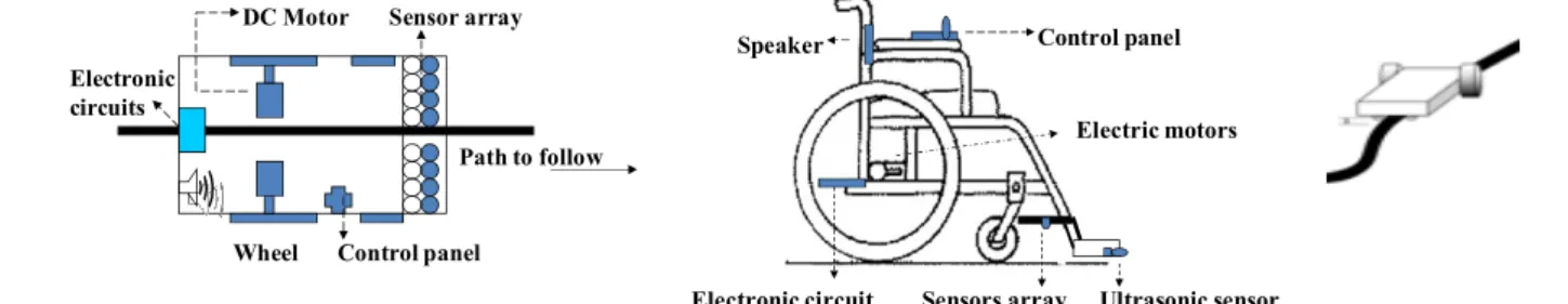
The ' Smart Mechatronic Robotic Guidance System-Mechatronics Motawif' ' is a mobile line follower
robotic system in the form of smart wheelchair, it is to design an integrated sensor array that will be mounted on mobile platform. A single battery will power the sensors, as well as, a control unit, drive circuit, and actuators. The two rear wheels are responsible of moving the wheelchair, but are also used to turn the wheelchair in any required direction depending on the difference of speed of wheels’ rotation between the right and left wheels (differential drive style).To give wheelchair a human-like property of responding to stimuli, it is required to select and design an effective closed loop control system and control algorithm, where control unit takes an input signals from sensors and controls the actuators and correspondingly speed of wheels’ rotation, actuators will maneuver wheelchair to stay on a predetermined course, while using feedback mechanism for constantly correcting the errors in moves. The control is done in such a way that when a sensor senses desired path, the system follow it and in response to any deviation from the path, a signal from control unit is sent to the motors to slow down or even stops, then the difference of rotation speed makes it possible to make turns, or when sensor sense the presence of an object in the front side in a prescribed distance, signal from control unit is sent to stop motors until object is removed.
The tasks (functions), to be carried out by the proposed design: system is intended to help the elderly
and disabled to Perform Al Omrah and/or Al Hajj, mainly performing predetermined time driven motions in the form of Altawaf around holy Kaba and/or Alsa'ee between Alsafa and Almarwa, counts motions and sound corresponding Doaa, Robot-Motawif will have the obstacle detection feature, stops when an object is located in the front side, main of these tasks are illustrated in Figure 4(a).
The functional structure block and preliminary flowchart of proposed mechatronics system is shown in
Figure 4(b).
Morphological table and analysis ( see Table 2 ): Finding solutions for each function in functional block,
including: switching system ON-OFF, Path and obstacle detection, motions, stops, turns, timing, counting, sounding. Next, filteringthesolutions: for every solutiondoes the solution satisfy all the requirements?Is there a solution which is really similar or evens the same? c) If yes, condense them to one solution. Finally evaluating the optimal concepts and if satisfies customer needs, optimal solutions can be selected.
Preliminary block diagram and layout representations of proposed system and main components are
shown in Figure 4(c), an assembled CAD model for the robot to be introduced.
A preliminary economic analysis: feasibility, cost-benefit evaluation: For now, it can be declare that, it is
possible to design and build such mechatronics system, to perform required tasks, and achieving most user needs and to be cost effective, major components are available and can be bought from local market, the total and final cost analysis, as well as, cost-benefit evaluation can be done after accomplishing theoretical selection and design of the whole system, the suggested design can be very helpful for pilgrims with disabilities or special needs .
Innovative Systems Design and Engineering ISSN 2222-1727 (Paper) ISSN 2222-2871 (Online Vol.4, No.10, 2013
Figure 3 Preliminary concept of robotic guidance system, in the form of wheelchair.
Figure 4(a): Functional block diagram.
Table 2 Morphological table, analysis and evaluation of the best solution.
Switching system On, Off
Detecting : path , obstacle
Movements : move, stop, turn ,slow
Counting , timing, sounding
Movements : move, stop, turn ,slow No
No
Yes
Yes
Smooth without kicks
Innovative Systems Design and Engineering 2871 (Online)
Figure 3 Preliminary concept of robotic guidance system, in the form of wheelchair.
Figure 4(a): Functional block diagram. Figure 4(b) Performing Altawaf and Alsa'ee accomplish, step by step; sequences,
corresponding action for each step.
Morphological table, analysis and evaluation of the best solution.
Sensors, program
Electric motor Wheels , Sensor, program Smooth without kicks
IC ,program
Electric motor Sensor, program Smooth without kicks
Sensors, program transmission D 1 2 3 5 A 7 B 6 C E F G I 4 ALSAFA
EXIT FROM HARAM ,PARKING , switch to hand control
A: Start of Altawaf, Doaa B: Alruk alyamany, Doaa C: Doaa
D: Maqam Ebraheem; Turning, Timing ; E: To Alsafa
F: Alsafa;,turning, timing, G,I : Alsaee between Asafa & Almarwa H: Almarwa, turning, timing, J: Exit from FARAM
: Sign and Doaa number, where there is Doaa www.iiste.org
Figure 3 Preliminary concept of robotic guidance system, in the form of wheelchair.
Figure 4(b) Performing Altawaf and Alsa'ee; tasks to accomplish, step by step; sequences, locations, and
corresponding action for each step.
Morphological table, analysis and evaluation of the best solution.
H
J 8
ALMARWA
EXIT FROM HARAM ,PARKING , switch to hand control
A: Start of Altawaf, Doaa1 IJ KLKMNا PQRSا... B: Alruk alyamany, Doaa2 C: Doaa3 ; KTUأ .... KTJر
D: Maqam Ebraheem; Turning, Timing ; ةYZSا E: To Alsafa
F: Alsafa;,turning, timing, Doaa4 G,I : Alsaee between Asafa & Almarwa H: Almarwa, turning, timing, Doaa5,6 J: Exit from FARAM
Innovative Systems Design and Engineering www.iiste.org ISSN 2222-1727 (Paper) ISSN 2222-2871 (Online)
Vol.4, No.10, 2013
Figure 4(c)
Figure 4(d)
Figure 4(C)(d) Preliminary system and block diagram layout representations of proposed system including main components
.
3.3 Parallel (concurrent) selection, design and integration of sub-systems and whole system: Mechanical, Control, information processing Software, Electronics, and interface design and integration.
Mechatronics engineer is expected to design products with synergy and integration toward constrains like higher performance, speed, precision, efficiency, lower costs and functionality, also the mechatronics engineer must be skilled in the modeling, simulation, analysis, and control of dynamic systems and understand the key issues in hardware implementation.Mechatronics systems design is Modern interdisciplinary design procedure; it is a concurrent selection, evaluation, integration, and optimization of the system and all its components as a whole and concurrently all the design disciplines work in parallelandcollaboratively throughout the design and development process to produce an overall optimal design– no after-thought add-ons allowed. The ideal process of concurrent or simultaneous engineering is characterized by parallel work of a potentially distributed community of designers that know about the parallel work of their colleagues and collaborate as necessary; sharing of knowledge in a common database builds a basis of cooperative design, since a shared database is the place where all design results are integrated [33]. The design of mechatronic systems can be facilitated using a methodology called systems engineering. Systems engineering is an interdisciplinary collaborative robust approachthat integrates disciplines and technologies to the design, creation, and operation of systems to ensure that the customer's needs are satisfied throughout a system's entire life cycle.once the system is specified after a problem statement, conceptual design general problem solving procedure and determination of all necessary requirements, it can be divided into realizable modules the optimal selection, modeling, evaluation, the exchange of information between differentmodules ((Figure 5(b)) and models of different domains (e.g. MCAD, ECAD), and synergetic integration of modules and all components to be designed in parallel and collaboratively with respect to the realization of the design specifications and requirements in the different domains, to produce an overall optimal design, it is desired that (sub-) models be reusable.
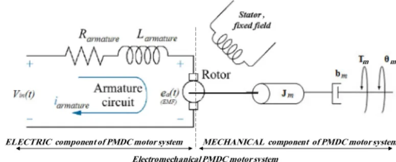
A mechatronic system will consist of many different types of interconnected subsystems (components and elements). As a result there will be energy conversion from one form to another, particularly between electrical energy and mechanical energy. This enables one to use energy as the unifying concept in the analysis and design of a mechatronic system [7].
3.3.1 Mechatronic – basic approach
Regardless of the type of mechatronic system, there is a need to understand the fundamental working principles of mechatronic systems before approaching the design procedure of a mechatronic product. The general scheme, shown in Figure 5(a), is an example of a mechanical system which is a power-producing or power-generating machine. The basis of many mechatronic systems is the mechanical part, which converts or transmits the mechanical process. Information on the state of the mechanical process has to be obtained by
DC motor R ig ht w he el Gears Mobile wheelchair P ot
Electronic components; Control unit , Power supply
L ef t w he el Speed sensor P ot Sensor array C o n tr o l u n it Obstacle detection sensor path detection sensor Left Motor Right Motor si g n al , co n d it io n in g an d I n te rf ac in g si g n al , co n d it io n in g an d I n te rf ac in g Speed sensor P la n t lo ad
Innovative Systems Design and Engineering ISSN 2222-1727 (Paper) ISSN 2222-2871 (Online Vol.4, No.10, 2013
measuring generalized flows (e.g. speed, mass flow) or electrical current/potentials (e.g. temperature, speed). Together with the reference variables, the measured variables are the inputs for an inform
digital electronics convert into manipulated variables for the actuators (e.g. motors) or for monitored variables to display. The addition and integration of feedback information flow to a feed forward energy flow in the mechanical system (e.g. motor drive, drainage pump) is one of the characteristics of many mechatronic systems. Interactions of man and machine have been profoundly enhanced by the development of electronics and IT technologies (e.g. SMS, voice control) and interactions
potential benefits of mechatronics come from the innovation potential of the technologies and the functional and spatial integration of the technologies [2].
Figure 5(a) Working principle of mechatro products auxiliary [16]
3.3.2 Ways of integration
Integration refers to combining disparate data or systems so they work as one system.
within a mechatronics system can be performed in two kinds, through the integration of components (hardware integration) and through the integration by information processing (software integration). The integration of components results from designing the mechatronics system as an overall system, and embedding the sensor, actuators, and microcomputers into the mechanical process, the microcomputers can be integrated with actuators, the process, or sensor or be arranged at several places. Int
sensors, and integrated actuators and microcomputers developed into smart actuators. For large systems bus connections will replace the many cable. Hence, there are several possibilities to build up an integ
system by proper integration of the hardware. The integration by information processing is based on advanced control function [10].
The principle of synergy in Mechatronics means, an integrated and concurrent design should result in a better product than one obtained through an uncoupled or sequential design [7].
3.3.3 Mechanical systems are concerned with the behavior of matter under the action of forces; su
are categorized as rigid, deformable, or fluid in nature.
that changes in the mechanical structure and other subsystems be evaluated simultaneously; a badly designed mechanical system will never be able to give a good performance by adding a sophisticated controller, therefore, Mechatronic systems design requires that a mechanical system, dynamics and its control system structure be designed as an integrated system (this desired that (sub
simulated to obtain unified model of both, that will simply the analysis and prediction of whole system effects and performance, it is important that during an early stage of the design a proper choic
respect to the mechanical properties needed to achieve a good performance of the controlled system.
1) Identify functional requirements and design parameters; the mechanical design involves the selection and design of all mechanical aspects in full details, to meet the machine system requirement specifications, it is crucial since it forms the skeleton of mechatronic systems.
dimensions, materials, type of joint combination, (revolute joints number of degrees of freedom etc. 3)
integration and imbedding issues such as positioning of sensors, actuators and microcomputers
constructive specifications using e.g. CAD/CAE tools, static and dynamic models for individual components, whole system and system layout.
3.3.3.1 Mechanical systems design 'Smart mechatronic robotic guidance system'
system requirements, the functional requirements and design parameters for proposed design are listed below. The optimal and necessary mechanical structure is shown in Figure
Innovative Systems Design and Engineering 2871 (Online)
measuring generalized flows (e.g. speed, mass flow) or electrical current/potentials (e.g. temperature, speed). Together with the reference variables, the measured variables are the inputs for an inform
digital electronics convert into manipulated variables for the actuators (e.g. motors) or for monitored variables to display. The addition and integration of feedback information flow to a feed forward energy flow in the stem (e.g. motor drive, drainage pump) is one of the characteristics of many mechatronic systems. Interactions of man and machine have been profoundly enhanced by the development of electronics and IT technologies (e.g. SMS, voice control) and interactions have become more versatile and user
potential benefits of mechatronics come from the innovation potential of the technologies and the functional and spatial integration of the technologies [2].
5(a) Working principle of mechatronic products auxiliary [16]
Figure 5(b) Exchange of information between different models
Integration refers to combining disparate data or systems so they work as one system.
within a mechatronics system can be performed in two kinds, through the integration of components (hardware integration) and through the integration by information processing (software integration). The integration of m designing the mechatronics system as an overall system, and embedding the sensor, actuators, and microcomputers into the mechanical process, the microcomputers can be integrated with actuators, the process, or sensor or be arranged at several places. Integrated sensors and microcomputers lead to smart sensors, and integrated actuators and microcomputers developed into smart actuators. For large systems bus connections will replace the many cable. Hence, there are several possibilities to build up an integ
system by proper integration of the hardware. The integration by information processing is based on advanced in Mechatronics means, an integrated and concurrent design should result in a better product than one obtained through an uncoupled or sequential design [7].
are concerned with the behavior of matter under the action of forces; su
are categorized as rigid, deformable, or fluid in nature. During the design of mechatronic systems, it is important that changes in the mechanical structure and other subsystems be evaluated simultaneously; a badly designed l never be able to give a good performance by adding a sophisticated controller, therefore, Mechatronic systems design requires that a mechanical system, dynamics and its control system structure be
this desired that (sub-)models be reusable), and correspondingly modeled and simulated to obtain unified model of both, that will simply the analysis and prediction of whole system effects and performance, it is important that during an early stage of the design a proper choic
respect to the mechanical properties needed to achieve a good performance of the controlled system.
Identify functional requirements and design parameters; the mechanical design involves the selection and cts in full details, to meet the machine system requirement specifications, it is crucial since it forms the skeleton of mechatronic systems. 2) Identify the necessary mechanical structure, dimensions, materials, type of joint combination, (revolute joints prismatic joint) supports, and the required
3) During the mechanical design process, suggest advices related to hardware integration and imbedding issues such as positioning of sensors, actuators and microcomputers
constructive specifications using e.g. CAD/CAE tools, static and dynamic models for individual components,
design 'Smart mechatronic robotic guidance system':
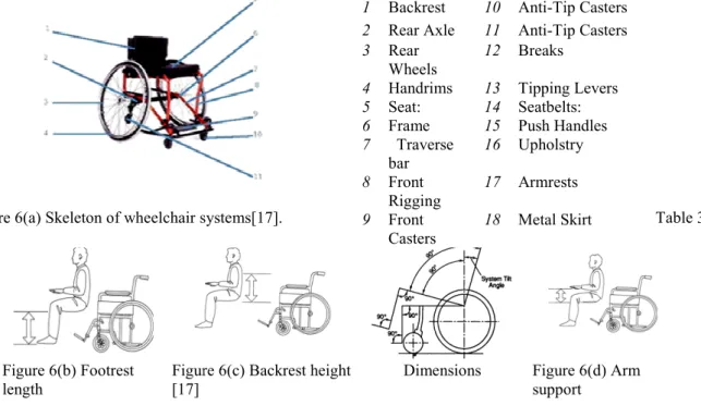
equirements, the functional requirements and design parameters for proposed design are listed below. The optimal and necessary mechanical structure is shown in Figure 6 (a) and main components are listed in www.iiste.org
measuring generalized flows (e.g. speed, mass flow) or electrical current/potentials (e.g. temperature, speed). Together with the reference variables, the measured variables are the inputs for an information flow, which the digital electronics convert into manipulated variables for the actuators (e.g. motors) or for monitored variables to display. The addition and integration of feedback information flow to a feed forward energy flow in the stem (e.g. motor drive, drainage pump) is one of the characteristics of many mechatronic systems. Interactions of man and machine have been profoundly enhanced by the development of electronics and IT have become more versatile and user-friendly. The potential benefits of mechatronics come from the innovation potential of the technologies and the functional and
Exchange of information between models
Integration refers to combining disparate data or systems so they work as one system. The integration within a mechatronics system can be performed in two kinds, through the integration of components (hardware integration) and through the integration by information processing (software integration). The integration of m designing the mechatronics system as an overall system, and embedding the sensor, actuators, and microcomputers into the mechanical process, the microcomputers can be integrated with actuators, egrated sensors and microcomputers lead to smart sensors, and integrated actuators and microcomputers developed into smart actuators. For large systems bus connections will replace the many cable. Hence, there are several possibilities to build up an integrated overall system by proper integration of the hardware. The integration by information processing is based on advanced in Mechatronics means, an integrated and concurrent design should result in a better are concerned with the behavior of matter under the action of forces; such systems During the design of mechatronic systems, it is important that changes in the mechanical structure and other subsystems be evaluated simultaneously; a badly designed l never be able to give a good performance by adding a sophisticated controller, therefore, Mechatronic systems design requires that a mechanical system, dynamics and its control system structure be ), and correspondingly modeled and simulated to obtain unified model of both, that will simply the analysis and prediction of whole system effects and performance, it is important that during an early stage of the design a proper choice can be made with respect to the mechanical properties needed to achieve a good performance of the controlled system.
Identify functional requirements and design parameters; the mechanical design involves the selection and cts in full details, to meet the machine system requirement specifications, it is Identify the necessary mechanical structure, prismatic joint) supports, and the required During the mechanical design process, suggest advices related to hardware integration and imbedding issues such as positioning of sensors, actuators and microcomputers. 4) Build constructive specifications using e.g. CAD/CAE tools, static and dynamic models for individual components,
: Refering to user and equirements, the functional requirements and design parameters for proposed design are listed below. (a) and main components are listed in
Innovative Systems Design and Engineering ISSN 2222-1727 (Paper) ISSN 2222-2871 (Online Vol.4, No.10, 2013
Table 3. Performance specifications;
(overshoot), the required optimal output linear velocity of the wheelchair is 0.05 m/s, in 2 seconds, the optimal wheel radius is 0.075 meter. Size and dimensions
meter, Length: 0.60 meter. Weight:
career the average wheelchair mass 55 kg, range for user weight 50:120 kg. be achieved if the user's body fits comfortably into the chair seat.
90° between the user's thighs and hips is achieved, most people will be comfortable if their knees are also at an angle of approximately 90°. Backrest height (
backrest, which should be high enough to stabilize the upper lumbar region. Above this level, the backrest height is a matter of individual need and/or personal preference.
properly adjusted they should support the user's forearms comfortably with the elbows at 90°. If they are too high, the user's shoulders will be hunched; if they are too low, the user will tend to slump to one side
Wheels: Tires to choose wheel diameter and material to result in the required linear velocity, where the relation
between wheel radius and linear velocity is given by solid ones but may puncture. Puncture
hard-wearing but can provide a rougher ride.
selection, To choose the gear ratio value to result in the required correspondingly to choose Gear'smaterial, number of teeth , radius.
Figure 6(a) Skeleton of wheelchair systems[17].
Figure 6(b) Footrest length
Figure 6(c) Backrest height [17]
3.3.4 Actuators selection and integration
acting on the basic system. In mechatronic systems, the actuator runs a certain kind of mechanical load process. This can be a position, speed, acceleration, torque (force), power or a comb
in a design depends on load process, power and torque requirements, position accuracy, speed range, available volume, transmission, integration in whole construction, surrounding, control unit, drive, and costs that the important roles; 1) To select and identify actuator, as completely as possible
units (e.g. electric, pneumatic, hydraulic
demand specifications. The factors must be taken into consideration when selecting the type of actuators include; actuator type, motion, load, power capacities, speed range, and positioning accuracy
related to actuators placement and
student should be able to meet both the power requirements as well as the torque requirements. The student has to have an appreciation of any out of balance loads and load related inertias.
3.3.5 Sensors selection and integration
information signal to the control unit. In a mechatronic systems, the sensor measures a certain kind of process variable, this can be a position, speed, acceleration,
controlled variables, several characteristics become important: the integration with the process, the dynamics of the sensor, stability, resolution, precision, robustness, size, cost, and signal proces
sensor as completely as possible from commercially available units
Innovative Systems Design and Engineering 2871 (Online)
Performance specifications; For smooth driving for comfortable riding and
(overshoot), the required optimal output linear velocity of the wheelchair is 0.05 m/s, in 2 seconds, the optimal
Size and dimensions: space saving wheelchair; Height: about 1 met
Weight: A lighter wheelchair is usually an advantage for both an active user and a
career the average wheelchair mass 55 kg, range for user weight 50:120 kg. Seat size: Maximum stability will ser's body fits comfortably into the chair seat. Footrest length (Figure
90° between the user's thighs and hips is achieved, most people will be comfortable if their knees are also at an
Backrest height (Figure 6 (c)): The upper body is stabilized by the support from the
backrest, which should be high enough to stabilize the upper lumbar region. Above this level, the backrest height is a matter of individual need and/or personal preference. Arm support (Figure 6 (d)):
properly adjusted they should support the user's forearms comfortably with the elbows at 90°. If they are too high, the user's shoulders will be hunched; if they are too low, the user will tend to slump to one side
to choose wheel diameter and material to result in the required linear velocity, where the relation between wheel radius and linear velocity is given by V=ω*r. Pneumatic - offer a better shock absorption than cture-proof - filled with a jelly like substance; need less maintenance. Solid wearing but can provide a rougher ride. Gear ratio : can be finally selected after final actuator type selection, To choose the gear ratio value to result in the required torque and output linear velocity, and
material, number of teeth , radius.
Figure 6(a) Skeleton of wheelchair systems[17].
Figure 6(c) Backrest height Dimensions Figure 6(d) Arm support
selection and integration; Converts an information signal from the control unit, into energy
acting on the basic system. In mechatronic systems, the actuator runs a certain kind of mechanical load process. This can be a position, speed, acceleration, torque (force), power or a combination. The selection of actuator type in a design depends on load process, power and torque requirements, position accuracy, speed range, available volume, transmission, integration in whole construction, surrounding, control unit, drive, and costs that
To select and identify actuator, as completely as possible from commercially available hydraulic..) to match the kinematic and dynamic requirements that
actors must be taken into consideration when selecting the type of actuators include; actuator type, motion, load, power capacities, speed range, and positioning accuracy
placement and integration issues. Power and torque requirements
student should be able to meet both the power requirements as well as the torque requirements. The student has to have an appreciation of any out of balance loads and load related inertias.
lection and integration; Sensors converts a state variable of the basic system, into an
information signal to the control unit. In a mechatronic systems, the sensor measures a certain kind of process variable, this can be a position, speed, acceleration, torque (force), power or a combination
controlled variables, several characteristics become important: the integration with the process, the dynamics of the sensor, stability, resolution, precision, robustness, size, cost, and signal processing 1)
from commercially available units (e.g., switches, potentiometer, tachometers,
1 Backrest 10 Anti-Tip Casters
2 Rear Axle 11 Anti-Tip Casters
3 Rear Wheels
12 Breaks
4 Handrims 13 Tipping Levers
5 Seat: 14 Seatbelts:
6 Frame 15 Push Handles
7 Traverse bar 16 Upholstry 8 Front Rigging 17 Armrests 9 Front Casters 18 Metal Skirt www.iiste.org
riving for comfortable riding and minimum kicks (overshoot), the required optimal output linear velocity of the wheelchair is 0.05 m/s, in 2 seconds, the optimal : space saving wheelchair; Height: about 1 meter, Width: 0.60 A lighter wheelchair is usually an advantage for both an active user and a Maximum stability will Figure 6 (b)): If an angle of 90° between the user's thighs and hips is achieved, most people will be comfortable if their knees are also at an The upper body is stabilized by the support from the backrest, which should be high enough to stabilize the upper lumbar region. Above this level, the backrest height (d)): When armrests are properly adjusted they should support the user's forearms comfortably with the elbows at 90°. If they are too high, the user's shoulders will be hunched; if they are too low, the user will tend to slump to one side [17*]. to choose wheel diameter and material to result in the required linear velocity, where the relation offer a better shock absorption than filled with a jelly like substance; need less maintenance. Solid - can be finally selected after final actuator type torque and output linear velocity, and
Table 3
Figure 6(d) Arm support
Converts an information signal from the control unit, into energy acting on the basic system. In mechatronic systems, the actuator runs a certain kind of mechanical load process. The selection of actuator type in a design depends on load process, power and torque requirements, position accuracy, speed range, available volume, transmission, integration in whole construction, surrounding, control unit, drive, and costs that playing from commercially available ..) to match the kinematic and dynamic requirements that meets the actors must be taken into consideration when selecting the type of actuators to use include; actuator type, motion, load, power capacities, speed range, and positioning accuracy, 2) Suggest advices
wer and torque requirements: In sizing the motor, student should be able to meet both the power requirements as well as the torque requirements. The student has converts a state variable of the basic system, into an information signal to the control unit. In a mechatronic systems, the sensor measures a certain kind of process torque (force), power or a combination, when measuring controlled variables, several characteristics become important: the integration with the process, the dynamics of
1) To select and identify (e.g., switches, potentiometer, tachometers,
Tip Casters Tip Casters Breaks Tipping Levers Seatbelts: Push Handles Upholstry Armrests Metal Skirt
Innovative Systems Design and Engineering www.iiste.org ISSN 2222-1727 (Paper) ISSN 2222-2871 (Online)
Vol.4, No.10, 2013
incremental optical encoders, resolvers…) to meet the task requirements. 2) Suggest advices related to sensor placement and integration issues the integration of sensors and signal processing, on common carrier, or one chip.
3.3.6 Output signal, conditioning and interfacing selection, design and integration; Selecting sensors and
actuators is followed by selecting and integrating power supplies, drive, and signal processing conditioning circuits, in order to interface the system components. In this stage, Power supplies, amplifiers, converters DAC, ADC, amplifiers, analog signal conditioning circuits, and power transistors are selected in order to match the sensor, controller and actuators specifications and ratings. The real-time interface process falls into the electrical and information system categories. In mechatronics, the main purpose of the real-time interface system is to provide data acquisition and control functions for microcomputer. The purpose of the acquisition function is to reconstruct a sensor waveform as a digital sequence and make it available to the computer software for processing.In this stage suggest advices related to Interface placement and integration issues
3.3.7 Control unit selection and integration: The most critical decision in the Mechatronics design process is
the control unit selection (physical controller).The controller is the central and most important part (brain) of the mechatronic system, it reads the input signals representing the state of the system, compares them to the desired states, and outputs signals to the actuators to control the physical system. There are a number of possible options including but not limited to: Microcontroller/microprocessor (e.g. PIC-microcontroller), Programmable logic controller (PLC), computer control; desktop/laptop, Digital Signal Processing (DSP) integrated circuits. In this stage suggest advices related to Control unitplacement and integration issues.
3.3.8 Control algorithm selection: The control unit and control algorithm selections are directly related to each
other, there are many controller algorithms that can be used for mechatronic systems including but not limited to : ON-OFF control, P, PI, PD and PID control, intelligent control, Fuzzy control, adaptive control, Neural network control. The main factors that might influence the decision on selecting certain control unit and algorithm include; simplicity, space and integration, processing power, environment (e.g. industrial, soft.. ), precision, robustness, unit cost, cost of final product, programming language, safety criticality of the application, required time to market, reliability and number of products to be produced.
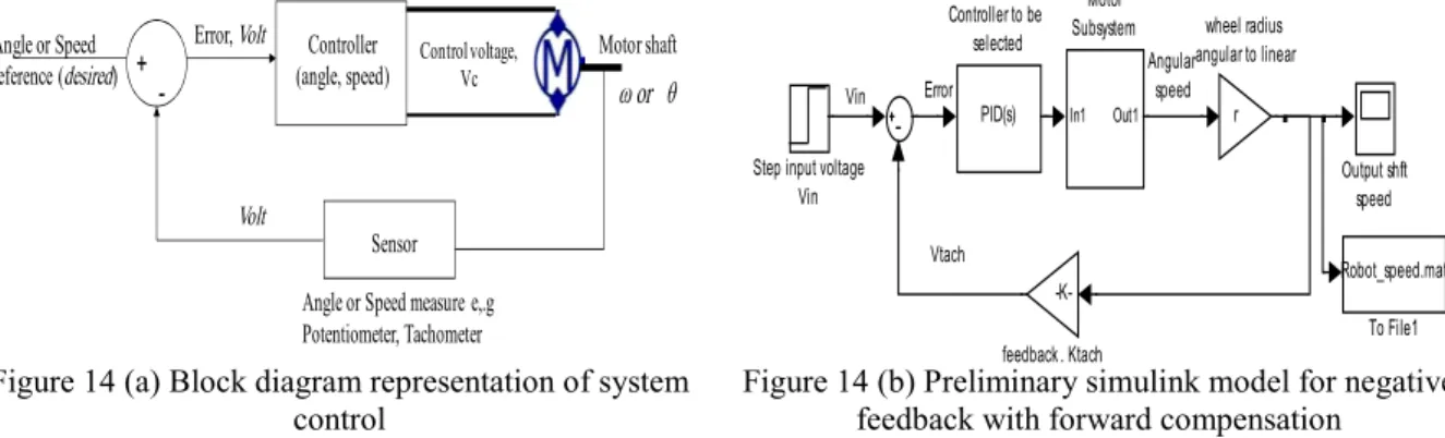
3.3.8.1 Control system design: The term control system design refers to the process of selecting feedback gains
structures and parameters that meet design specifications in a closed-loop control system. Most design methods are iterative, combining parameter selection with analysis, simulation, and insight into the dynamics of the plant. [18-19].
3.3.9 Selection and integration of human–machine interaction field: Control of the machine, and feedback
from the machine which aids the user ( e.g operator , customer) in making operational decisions, including but not limited to : efficient, simple and easy to understand and use interface , enjoyable to operate a machine, simple input/ output means such as LEDs, digital display, LCD, touch screens, voice activation.
3.3.10 Develop complete and detailed system block diagram layout: Based on system's sub-systems and
components selection, design and integration, a complete and detailed system block diagram layout is developed, showing interconnections and interrelation and energy flow.
3.3.11 Parallel (concurrent) design, integration and optimization of sub-systems and whole system: 'Smart
mechatronic robotic guidance system': The proposed design of smart wheelchair is an application form of line follower mobile robot, intended to help and support people with disabilities and special needs to perform specific predetermined tasks particularly, motion around holy Kaba, Makka. Two, top and side, views of proposed system design are shown in Figure 7. Such mobile Robot can be designed and built using the following components; two in-line with each other actuators, two drive circuit for each actuator, embedded sensors for path detection, range detection and speed sensors, a control unit embedded within the system and based on inputs state, capable of controlling two drive channels, controls the motion of wheelchair robot. Usually, mobile platforms are supported by two driving rear wheels; and with stability augmented by one or two front caster wheel(s) . The two rear wheels are responsible of moving the robot, and used to turn the robot in any required direction depending on the difference of speed of wheels’ rotation between the right and left wheels.
3.3.11.1 Actuators selection and integration: The accurate control of motion is a fundamental concern in
mechatronics applications, where placing or moving an object in the exact desired location or with desired speed with the exact possible amount of force and torque at the correct exact time, while consuming minimum electric power, at minim cost, is essential for efficient system operation. Motion control is a sub-field of control engineering, in which the position or velocity of a given machine are controlled using some type of actuating machine. The actuating machines most used in mechatronics motion control systems are DC machines (motors). There are many DC machines that may be more or less appropriate to a specific type of application each has its advantages, limitations and disadvantages; electric motors are characterized with excellent performance in motion control, due simple principle of working, quick instantaneous and accurate torque generation, also are capable of generating high torque at low speed, can operate efficiently over a greater range of speeds, as well as


![Figure 17 MOBS Mobile Robot Simulator [32]](https://thumb-us.123doks.com/thumbv2/123dok_us/11022642.2989543/26.892.135.795.153.624/figure-mobs-mobile-robot-simulator.webp)
